EP1319787B1 - Luftdämpfer für bewegliche Möbelteile - Google Patents
Luftdämpfer für bewegliche Möbelteile Download PDFInfo
- Publication number
- EP1319787B1 EP1319787B1 EP02026882A EP02026882A EP1319787B1 EP 1319787 B1 EP1319787 B1 EP 1319787B1 EP 02026882 A EP02026882 A EP 02026882A EP 02026882 A EP02026882 A EP 02026882A EP 1319787 B1 EP1319787 B1 EP 1319787B1
- Authority
- EP
- European Patent Office
- Prior art keywords
- cylinder
- diameter
- air damper
- piston
- damper according
- Prior art date
- Legal status (The legal status is an assumption and is not a legal conclusion. Google has not performed a legal analysis and makes no representation as to the accuracy of the status listed.)
- Expired - Lifetime
Links
- 238000007789 sealing Methods 0.000 claims description 12
- 239000006096 absorbing agent Substances 0.000 abstract 1
- 230000035939 shock Effects 0.000 abstract 1
- 230000000694 effects Effects 0.000 description 9
- 238000013016 damping Methods 0.000 description 4
- 238000003780 insertion Methods 0.000 description 4
- 230000037431 insertion Effects 0.000 description 4
- 230000006835 compression Effects 0.000 description 3
- 238000007906 compression Methods 0.000 description 3
- 238000010276 construction Methods 0.000 description 3
- 230000000994 depressogenic effect Effects 0.000 description 2
- 238000009434 installation Methods 0.000 description 2
- 239000007788 liquid Substances 0.000 description 2
- 230000009471 action Effects 0.000 description 1
- 230000002238 attenuated effect Effects 0.000 description 1
- 230000001419 dependent effect Effects 0.000 description 1
- 238000011835 investigation Methods 0.000 description 1
- 238000004519 manufacturing process Methods 0.000 description 1
- 230000007246 mechanism Effects 0.000 description 1
- 230000004048 modification Effects 0.000 description 1
- 238000012986 modification Methods 0.000 description 1
- 230000007704 transition Effects 0.000 description 1
Images


Classifications
-
- E—FIXED CONSTRUCTIONS
- E05—LOCKS; KEYS; WINDOW OR DOOR FITTINGS; SAFES
- E05F—DEVICES FOR MOVING WINGS INTO OPEN OR CLOSED POSITION; CHECKS FOR WINGS; WING FITTINGS NOT OTHERWISE PROVIDED FOR, CONCERNED WITH THE FUNCTIONING OF THE WING
- E05F5/00—Braking devices, e.g. checks; Stops; Buffers
- E05F5/003—Braking devices, e.g. checks; Stops; Buffers for sliding wings
-
- A—HUMAN NECESSITIES
- A47—FURNITURE; DOMESTIC ARTICLES OR APPLIANCES; COFFEE MILLS; SPICE MILLS; SUCTION CLEANERS IN GENERAL
- A47B—TABLES; DESKS; OFFICE FURNITURE; CABINETS; DRAWERS; GENERAL DETAILS OF FURNITURE
- A47B96/00—Details of cabinets, racks or shelf units not covered by a single one of groups A47B43/00 - A47B95/00; General details of furniture
-
- A—HUMAN NECESSITIES
- A47—FURNITURE; DOMESTIC ARTICLES OR APPLIANCES; COFFEE MILLS; SPICE MILLS; SUCTION CLEANERS IN GENERAL
- A47B—TABLES; DESKS; OFFICE FURNITURE; CABINETS; DRAWERS; GENERAL DETAILS OF FURNITURE
- A47B88/00—Drawers for tables, cabinets or like furniture; Guides for drawers
- A47B88/40—Sliding drawers; Slides or guides therefor
- A47B88/453—Actuated drawers
- A47B88/46—Actuated drawers operated by mechanically-stored energy, e.g. by springs
- A47B88/467—Actuated drawers operated by mechanically-stored energy, e.g. by springs self-closing
-
- E—FIXED CONSTRUCTIONS
- E05—LOCKS; KEYS; WINDOW OR DOOR FITTINGS; SAFES
- E05F—DEVICES FOR MOVING WINGS INTO OPEN OR CLOSED POSITION; CHECKS FOR WINGS; WING FITTINGS NOT OTHERWISE PROVIDED FOR, CONCERNED WITH THE FUNCTIONING OF THE WING
- E05F1/00—Closers or openers for wings, not otherwise provided for in this subclass
- E05F1/08—Closers or openers for wings, not otherwise provided for in this subclass spring-actuated, e.g. for horizontally sliding wings
- E05F1/16—Closers or openers for wings, not otherwise provided for in this subclass spring-actuated, e.g. for horizontally sliding wings for sliding wings
-
- E—FIXED CONSTRUCTIONS
- E05—LOCKS; KEYS; WINDOW OR DOOR FITTINGS; SAFES
- E05F—DEVICES FOR MOVING WINGS INTO OPEN OR CLOSED POSITION; CHECKS FOR WINGS; WING FITTINGS NOT OTHERWISE PROVIDED FOR, CONCERNED WITH THE FUNCTIONING OF THE WING
- E05F5/00—Braking devices, e.g. checks; Stops; Buffers
- E05F5/02—Braking devices, e.g. checks; Stops; Buffers specially for preventing the slamming of swinging wings during final closing movement, e.g. jamb stops
-
- F—MECHANICAL ENGINEERING; LIGHTING; HEATING; WEAPONS; BLASTING
- F16—ENGINEERING ELEMENTS AND UNITS; GENERAL MEASURES FOR PRODUCING AND MAINTAINING EFFECTIVE FUNCTIONING OF MACHINES OR INSTALLATIONS; THERMAL INSULATION IN GENERAL
- F16F—SPRINGS; SHOCK-ABSORBERS; MEANS FOR DAMPING VIBRATION
- F16F9/00—Springs, vibration-dampers, shock-absorbers, or similarly-constructed movement-dampers using a fluid or the equivalent as damping medium
- F16F9/02—Springs, vibration-dampers, shock-absorbers, or similarly-constructed movement-dampers using a fluid or the equivalent as damping medium using gas only or vacuum
- F16F9/0209—Telescopic
-
- F—MECHANICAL ENGINEERING; LIGHTING; HEATING; WEAPONS; BLASTING
- F16—ENGINEERING ELEMENTS AND UNITS; GENERAL MEASURES FOR PRODUCING AND MAINTAINING EFFECTIVE FUNCTIONING OF MACHINES OR INSTALLATIONS; THERMAL INSULATION IN GENERAL
- F16F—SPRINGS; SHOCK-ABSORBERS; MEANS FOR DAMPING VIBRATION
- F16F9/00—Springs, vibration-dampers, shock-absorbers, or similarly-constructed movement-dampers using a fluid or the equivalent as damping medium
- F16F9/32—Details
- F16F9/3207—Constructional features
- F16F9/3235—Constructional features of cylinders
- F16F9/3242—Constructional features of cylinders of cylinder ends, e.g. caps
-
- F—MECHANICAL ENGINEERING; LIGHTING; HEATING; WEAPONS; BLASTING
- F16—ENGINEERING ELEMENTS AND UNITS; GENERAL MEASURES FOR PRODUCING AND MAINTAINING EFFECTIVE FUNCTIONING OF MACHINES OR INSTALLATIONS; THERMAL INSULATION IN GENERAL
- F16F—SPRINGS; SHOCK-ABSORBERS; MEANS FOR DAMPING VIBRATION
- F16F9/00—Springs, vibration-dampers, shock-absorbers, or similarly-constructed movement-dampers using a fluid or the equivalent as damping medium
- F16F9/32—Details
- F16F9/36—Special sealings, including sealings or guides for piston-rods
- F16F9/366—Special sealings, including sealings or guides for piston-rods functioning as guide only, e.g. bushings
-
- A—HUMAN NECESSITIES
- A47—FURNITURE; DOMESTIC ARTICLES OR APPLIANCES; COFFEE MILLS; SPICE MILLS; SUCTION CLEANERS IN GENERAL
- A47B—TABLES; DESKS; OFFICE FURNITURE; CABINETS; DRAWERS; GENERAL DETAILS OF FURNITURE
- A47B88/00—Drawers for tables, cabinets or like furniture; Guides for drawers
- A47B88/40—Sliding drawers; Slides or guides therefor
- A47B2088/4015—Sliding drawers; Slides or guides therefor with magnets holding the drawer in closed position
-
- A—HUMAN NECESSITIES
- A47—FURNITURE; DOMESTIC ARTICLES OR APPLIANCES; COFFEE MILLS; SPICE MILLS; SUCTION CLEANERS IN GENERAL
- A47B—TABLES; DESKS; OFFICE FURNITURE; CABINETS; DRAWERS; GENERAL DETAILS OF FURNITURE
- A47B2210/00—General construction of drawers, guides and guide devices
- A47B2210/0091—Drawer movement damping
- A47B2210/0094—Drawer damping device with 2 relatively movable parts to convert kinetic energy
-
- E—FIXED CONSTRUCTIONS
- E05—LOCKS; KEYS; WINDOW OR DOOR FITTINGS; SAFES
- E05F—DEVICES FOR MOVING WINGS INTO OPEN OR CLOSED POSITION; CHECKS FOR WINGS; WING FITTINGS NOT OTHERWISE PROVIDED FOR, CONCERNED WITH THE FUNCTIONING OF THE WING
- E05F5/00—Braking devices, e.g. checks; Stops; Buffers
- E05F5/06—Buffers or stops limiting opening of swinging wings, e.g. floor or wall stops
- E05F5/08—Buffers or stops limiting opening of swinging wings, e.g. floor or wall stops with springs
-
- E—FIXED CONSTRUCTIONS
- E05—LOCKS; KEYS; WINDOW OR DOOR FITTINGS; SAFES
- E05F—DEVICES FOR MOVING WINGS INTO OPEN OR CLOSED POSITION; CHECKS FOR WINGS; WING FITTINGS NOT OTHERWISE PROVIDED FOR, CONCERNED WITH THE FUNCTIONING OF THE WING
- E05F5/00—Braking devices, e.g. checks; Stops; Buffers
- E05F5/06—Buffers or stops limiting opening of swinging wings, e.g. floor or wall stops
- E05F5/10—Buffers or stops limiting opening of swinging wings, e.g. floor or wall stops with piston brakes
-
- E—FIXED CONSTRUCTIONS
- E05—LOCKS; KEYS; WINDOW OR DOOR FITTINGS; SAFES
- E05Y—INDEXING SCHEME RELATING TO HINGES OR OTHER SUSPENSION DEVICES FOR DOORS, WINDOWS OR WINGS AND DEVICES FOR MOVING WINGS INTO OPEN OR CLOSED POSITION, CHECKS FOR WINGS AND WING FITTINGS NOT OTHERWISE PROVIDED FOR, CONCERNED WITH THE FUNCTIONING OF THE WING
- E05Y2201/00—Constructional elements; Accessories therefore
- E05Y2201/20—Brakes; Disengaging means, e.g. clutches; Holders, e.g. locks; Stops; Accessories therefore
- E05Y2201/21—Brakes
- E05Y2201/212—Buffers
-
- E—FIXED CONSTRUCTIONS
- E05—LOCKS; KEYS; WINDOW OR DOOR FITTINGS; SAFES
- E05Y—INDEXING SCHEME RELATING TO HINGES OR OTHER SUSPENSION DEVICES FOR DOORS, WINDOWS OR WINGS AND DEVICES FOR MOVING WINGS INTO OPEN OR CLOSED POSITION, CHECKS FOR WINGS AND WING FITTINGS NOT OTHERWISE PROVIDED FOR, CONCERNED WITH THE FUNCTIONING OF THE WING
- E05Y2201/00—Constructional elements; Accessories therefore
- E05Y2201/20—Brakes; Disengaging means, e.g. clutches; Holders, e.g. locks; Stops; Accessories therefore
- E05Y2201/252—Brakes; Disengaging means, e.g. clutches; Holders, e.g. locks; Stops; Accessories therefore characterised by type of friction
- E05Y2201/254—Fluid or viscous friction
- E05Y2201/256—Fluid or viscous friction with pistons or vanes
-
- E—FIXED CONSTRUCTIONS
- E05—LOCKS; KEYS; WINDOW OR DOOR FITTINGS; SAFES
- E05Y—INDEXING SCHEME RELATING TO HINGES OR OTHER SUSPENSION DEVICES FOR DOORS, WINDOWS OR WINGS AND DEVICES FOR MOVING WINGS INTO OPEN OR CLOSED POSITION, CHECKS FOR WINGS AND WING FITTINGS NOT OTHERWISE PROVIDED FOR, CONCERNED WITH THE FUNCTIONING OF THE WING
- E05Y2201/00—Constructional elements; Accessories therefore
- E05Y2201/20—Brakes; Disengaging means, e.g. clutches; Holders, e.g. locks; Stops; Accessories therefore
- E05Y2201/262—Brakes; Disengaging means, e.g. clutches; Holders, e.g. locks; Stops; Accessories therefore characterised by type of motion
- E05Y2201/264—Brakes; Disengaging means, e.g. clutches; Holders, e.g. locks; Stops; Accessories therefore characterised by type of motion linear
-
- E—FIXED CONSTRUCTIONS
- E05—LOCKS; KEYS; WINDOW OR DOOR FITTINGS; SAFES
- E05Y—INDEXING SCHEME RELATING TO HINGES OR OTHER SUSPENSION DEVICES FOR DOORS, WINDOWS OR WINGS AND DEVICES FOR MOVING WINGS INTO OPEN OR CLOSED POSITION, CHECKS FOR WINGS AND WING FITTINGS NOT OTHERWISE PROVIDED FOR, CONCERNED WITH THE FUNCTIONING OF THE WING
- E05Y2201/00—Constructional elements; Accessories therefore
- E05Y2201/40—Motors; Magnets; Springs; Weights; Accessories therefore
- E05Y2201/404—Motors; Magnets; Springs; Weights; Accessories therefore characterised by the function
- E05Y2201/41—Motors; Magnets; Springs; Weights; Accessories therefore characterised by the function for closing
- E05Y2201/412—Motors; Magnets; Springs; Weights; Accessories therefore characterised by the function for closing for the final closing movement
-
- E—FIXED CONSTRUCTIONS
- E05—LOCKS; KEYS; WINDOW OR DOOR FITTINGS; SAFES
- E05Y—INDEXING SCHEME RELATING TO HINGES OR OTHER SUSPENSION DEVICES FOR DOORS, WINDOWS OR WINGS AND DEVICES FOR MOVING WINGS INTO OPEN OR CLOSED POSITION, CHECKS FOR WINGS AND WING FITTINGS NOT OTHERWISE PROVIDED FOR, CONCERNED WITH THE FUNCTIONING OF THE WING
- E05Y2201/00—Constructional elements; Accessories therefore
- E05Y2201/40—Motors; Magnets; Springs; Weights; Accessories therefore
- E05Y2201/47—Springs; Spring tensioners
- E05Y2201/488—Traction springs
-
- E—FIXED CONSTRUCTIONS
- E05—LOCKS; KEYS; WINDOW OR DOOR FITTINGS; SAFES
- E05Y—INDEXING SCHEME RELATING TO HINGES OR OTHER SUSPENSION DEVICES FOR DOORS, WINDOWS OR WINGS AND DEVICES FOR MOVING WINGS INTO OPEN OR CLOSED POSITION, CHECKS FOR WINGS AND WING FITTINGS NOT OTHERWISE PROVIDED FOR, CONCERNED WITH THE FUNCTIONING OF THE WING
- E05Y2800/00—Details, accessories and auxiliary operations not otherwise provided for
- E05Y2800/20—Combinations of elements
- E05Y2800/23—Combinations of elements of elements of different categories
- E05Y2800/24—Combinations of elements of elements of different categories of springs and brakes
-
- E—FIXED CONSTRUCTIONS
- E05—LOCKS; KEYS; WINDOW OR DOOR FITTINGS; SAFES
- E05Y—INDEXING SCHEME RELATING TO HINGES OR OTHER SUSPENSION DEVICES FOR DOORS, WINDOWS OR WINGS AND DEVICES FOR MOVING WINGS INTO OPEN OR CLOSED POSITION, CHECKS FOR WINGS AND WING FITTINGS NOT OTHERWISE PROVIDED FOR, CONCERNED WITH THE FUNCTIONING OF THE WING
- E05Y2900/00—Application of doors, windows, wings or fittings thereof
- E05Y2900/20—Application of doors, windows, wings or fittings thereof for furnitures, e.g. cabinets
Definitions
- the invention relates to an air damper for movable furniture parts, such as Drawers or doors, consisting of a cylinder open on one side and one in this longitudinally slidably received piston with seal, on the a pestle connects.
- dampers for movable furniture parts in different configurations already known.
- these, i. the damper, with a high-viscosity liquid is filled.
- the object of the present invention is to provide an air damper for movable furniture parts, especially drawers or doors, to create the type of construction especially kept simple and is inexpensive to produce.
- a generic air damper is used to solve the problem constructed according to the features of claim 1.
- Identification is in a generic air damper in the jacket wall of the cylinder near the closed end portion of the cylinder Bore provided whose diameter relative to the cylinder diameter is much smaller.
- Investigations have shown that with this invention Design a very good braking effect is achieved, where it essential to the invention is that the bore in the shell and not in the ground of the cylinder is arranged. A corresponding provision of the holes in the ground of the cylinder leads to a much worse braking effect.
- the bore about 2.5% to 4%, preferably 3.3% of Cylinder diameter on.
- the piston of the air damper after insertion into the cylinder by a return device in its extended position may be.
- a restoring device there is a spring or a corresponding magnet at.
- the German utility model DE 201 17 031 of Cylinder be at least a two-stage telescopic cylinder.
- a buffer can be arranged at the free end of the plunger.
- the plunger can be particularly advantageous consist of two intersecting rods.
- a slot may be formed by which engages a pin arranged in the cylinder stationary.
- the movable Cylinder of the telescopic cylinder on the circumference at least two radially projecting Webs have their guidance in the fixed cylinder along allow at least one cylinder-fixed pin.
- four radially projecting webs along two are guided opposite cylindrical fixed pins.
- These cylinder-fixed pins can be embedded in corresponding holes in the cylinder.
- the piston have a groove tapering towards its end, in which an O-ring seal is loosely mounted so that they sealing in the direction of insertion of the piston is applied and stored loosely in the extension direction.
- a further preferred embodiment of the invention is that the shell wall of the cylinder at least two sections of different inner diameter in that the ram adjoining the piston has at least one Section, whose diameter matches the inner diameter of the section the cylinder is adapted, wherein the plunger a second seal for sealing has with respect to the jacket wall of the cylinder.
- the air damper 10 consists of a closed on one side Cylinder 12, in which a piston 14 is mounted longitudinally movable.
- the piston 14 has a seal 16.
- Tappet 18 With the piston 14 is in one piece Tappet 18 connected, which consists of two intersecting webs 20 and 22 respectively.
- the web 20 In the web 20 is a slot 24 except in which a cylindrical pin 26 engages.
- the cylinder-fixed pin 26 defines together with the slot 24 the depressed or the extended position of the piston 14, wherein the indented Position in Figure 6 and the extended position in Figure 7 is shown.
- the diameter of the bore 28 is preferably 3.3% of the inner diameter of the cylinder 12.
- the piston 14 has a groove 30 which tapered to the end of the piston 14 extends.
- the O-ring trained seal 16 stored, which is designed in diameter so is that when pushing the piston against a flange Stop 32 supported and stretched so far on the cone-shaped groove is that the O-ring during insertion of the piston sealingly against the Cylinder inner wall hugs.
- the O-ring slips when pulling out of the piston along the cone-shaped groove in the opposite Direction and attaches to the flange-like end 34 of the piston 14. hereby can the piston 14 completely free to pull out, this by a here not shown at the outer end of the plunger 18 arranged magnet can be done.
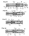
- FIG. 8 shows another embodiment of the air damper 10.
- the cylinder 12 constructed in the same way.
- the plunger 18 corresponds to the Structure according to the embodiment of Figures 6 and 7. Only the Piston 14 has a differently shaped seal 16 '.
- a buffer 36 stored at the outer end of the Plunger 18 .
- a compression spring 38 is arranged between the bottom of the cylinder 12 and the plunger 18 , which for the provision of the Piston 14 provides necessary restoring force.
- FIGS. 9 to 14 show a telescopic design of the air damper 10.
- basically the construction of the damper according to the German utility model 201 17 031.0 corresponds to the same applicant, wherein the throttle bore 28 for the air not in the top wall of the piston and in the cap, but according to the present invention in the cylinder jacket of the outer Cylinder 12 is provided.
- the piston 14 is in one Intermediate cylinder 13 out, which in turn telescopes relative to the cylinder 12 is.
- a return of the piston 14 with plunger 18 via a Compression spring 38 in Figure 9 in the extended position and in Figure 10 in compressed Position is shown.
- the plunger 18 also has in this embodiment, As shown in Figure 11 can be seen on a cross-shaped cross-section.
- the length of the webs 20 and 22 of the plunger 18 is less than the diameter of the piston 14, so that this in its initial position with respect to an end face Covenant 40 of the movable intermediate cylinder 13 is present.
- the movable intermediate cylinder 13 has 4 radially projecting webs 42, the leadership in the Cylinder 12 serve.
- pins 44 are recessed in the cylinder, as this is shown in FIG. These pins 44 prevent rotation of the intermediate cylinder 13 within the cylinder 12 due to the molded on this intermediate cylinder projecting webs 42.
- the displaceable intermediate cylinder 13 is further provided with a flange-shaped edge 46, which is in the starting position is supported against the pins 44 inserted into corresponding bores of the cylinder 12, as shown in FIG.
- the piston 14 is provided with a seal 16 'and the movable intermediate cylinder 13 is provided with a seal 48.
- the bore 28 is arranged.
- the spring 38 is between the Bottom of the cylinder 12 and the piston 14 is arranged.
- the movable intermediate cylinder 13 with flange 46 and seal 48 and in Figure 14 is the cylinder 12 with the bore 28 and the two mounting holes for the pins 44 shown.
- FIG. 1 shows a furniture carcass wall 100, to which a guide rail 101 is screwed.
- a guide rail 101 On this guide rail is an extendable Rail 104 guided over rollers or ball bearings 103 extendable, the extendable Guide rail 104 is fixedly connected to a drawer 105.
- the Body-side guide rail 101 With the Body-side guide rail 101 is connected to a unit 106, in which on the one hand, the air damper 10 and on the other hand, a spring-loaded drawer automatic entry 110 is arranged.
- the operation of this automatic catch is described in detail in EP 01 111 420.4, incorporated herein by reference becomes.
- FIG. 5 shows the housing of the assembly 106 without the automatic retraction mechanism 110 and the air damper 10th
- An air damper 50 is according to the embodiment, which in the figures 15, 16, and 17 is substantially formed of a cylinder 52 which is one-sided is closed with a lid 54.
- the inner wall of the shell wall of the cylinder 52 is in four sections 56, 58, 60 and 62 with different diameters (see Figures 15, 16 and 17) divided.
- a piston 64 has a seal 66 on. With the piston 64, a plunger 68 is integrally connected, which is approximately in his Center carries another seal 70. In the extended position shown in FIG 15, the seals 66 and 70 are in the sections 58 and 62 of the jacket wall of the cylinder 52. The seals are in this position sealingly, wherein they develop their sealing effect, in particular, when a furniture part against the plunger 68 presses, so that the air only through the appropriate Bore 72 can escape.
- the plunger 68 have a cavity 76 which via channels 78 with grooves 80, 81 for the seals 70 and 66 is connected.
- FIG. 18 shows a simplified embodiment of an air damper 50, in which the Mantelwandug the cylinder 52 only sections 56, 58 and 62nd having.
- the intermediate portion 60 is not shown in this embodiment.
- the plunger 68 does not have two regions of different diameters, but this has only one running over its entire length Diameter up. In this embodiment, therefore, the section 58 takes over the Function of the section 58 and the intermediate section 60 according to the before described embodiment according to Figures 15 to 17.
- the stroke of Piston 68 is, as in the previous variant via a discontinuous transition limited in the form of a step or a base 82.
- FIGS. 19 to 21 show a further alternative embodiment,
- the jacket wall of the cylinder 52 of an air damper 50 in five sections is divided, namely the sections 56, 58, 60, 62 and 63.
- the air damper 50 is formed in the same manner as in the embodiment according to the figures 15 to 17.
- a section 63 with a comparatively larger Diameter arranged.
- the diameter of the section 63 corresponds to that of section 60.
- the seal 70 now enters upon further pushing in of the plunger 68 the portion 60, which corresponds to the section 63 in diameter.
- the sealing effect of the seal 70 repealed.
- the seal 66 moves into the section 56 of the cylinder 52, so that also here Seal 66 no longer rests against the jacket wall.
- the plunger 68 acting counterforce so only generated by the spring 74.
- features such as example a groove 86 (see Figure 15 and Figure 19) for attaching the cylinder 52 to a Carrier or the arrangement of a buffer 88 at the free end of the plunger 68, are known per se and will not be described here.
Description
- die Figuren 1 bis 5:
- teilweise geschnittene Darstellungen, die den erfindungsgemäßen Luftzylinder in einem in eine Schubladenführung integrierten Anwendungsfall darstellen,
- die Figur 6:
- eine teilweise geschnittene Seitendarstellung eines Luftzylinders gemäß einer Ausführungsform der vorliegenden Erfindung,
- Figur 7:
- einen Luftzylinder gemäß der Darstellung nach Figur 6 im ausgezogenen Zustand,
- Figur 8:
- einen Luftzylinder, seitlich geschnitten gemäß einer alternativen Ausführungsvariante,
- Figur 9:
- einen Luftzylinder seitlich geschnitten gemäß einer weiteren Ausführungsform der Erfindung,
- Figur 10:
- eine geschnittene Darstellung des Luftzylinders gemäß Figur 9 im zusammengedrückten Zustand,
- Figur 11:
- eine Querschnittsdarstellung entlang der Schnittlinie XI - XI gemäß Figur 10,
- Figur 12:
- den Stößel mit Kolben gemäß einer Ausführungsform der Erfindung,
- Figur 13:
- den beweglichen Zwischenzylinder in seitlicher Darstellung,
- Figur 14:
- eine seitliche Darstellung eines Zylinders des erfindungsgemäßen Luftdämpfers,
- Figur 15 - 17:
- einen seitlich geschnittenen Luftzylinder gemäß einer anderen Ausführungsform der Erfindung in unterschiedlichen Positionen,
- Figur 18:
- eine weitere Ausführungsform eines erfindungsgemäßen Luftzylinders, ebenfalls seitlich geschnitten und
- die Figuren 19 -21:
- eine weitere Ausführungsvariante eines erfindungsgemäßen Luftzylinders, seitlich geschnitten, in unterschiedlichen Positionen.
Claims (15)
- Luftdämpfer (10) für bewegliche Möbelteile, wie beispielsweise Schubladen oder Türen, bestehend aus einem einseitig offenen Zylinder (12) und einem in diesem längsverschieblich aufgenommenen Kolben (14) mit Dichtung (16), an den ein Stößel (18) anschließt,
gekennzeichnet durch
eine in der Mantelwand des Zylinders nahe dem geschlossenen Endbereich des Zylinders angeordnete Bohrung (28) zum Entweichen von kompimierter Luft, deren Durchmesser gegenüber dem Zylinderdurchmesser wesentlich kleiner ist. - Luftdämpfer nach Anspruch 1, dadurch gekennzeichnet, daß die Bohrung einen Durchmesser aufweist, der 2,5 % bis 4 %, vorzugsweise 3,3 %, des Durchmessers des Zylinders aufweist.
- Luftdämpfer nach Anspruch 1 oder Anspruch 2, dadurch gekennzeichnet, daß der Kolben nach Einschieben in den Zylinder durch eine Rückstelleinrichtung in seine ausgeschobene Stellung zurückstellbar ist.
- Luftdämpfer nach Anspruch 3, dadurch gekennzeichnet, daß die Rückstelleinrichtung eine Feder oder ein Magnet ist.
- Luftdämpfer nach einem der Ansprüche 1 bis 4, dadurch gekennzeichnet, daß der Zylinder ein mindestens zweistufiger Teleskopzylinder ist.
- Luftdämpfer nach einem der Ansprüche 1 bis 5, dadurch gekennzeichnet, daß am freien Ende des Stößels ein Puffer angeordnet ist.
- Luftdämpfer nach einem der Ansprüche 1 bis 6, dadurch gekennzeichnet, daß der Stößel aus zwei sich kreuzenden Stegen besteht.
- Luftdämpfer nach Anspruch 7, dadurch gekennzeichnet, daß in einem der Stege des Stößels ein Langloch ausgebildet ist, durch welches ein ortsfest im Zylinder angeordneter Stift greift.
- Luftdämpfer nach Anspruch 5, dadurch gekennzeichnet, daß der bewegliche Zylinder des Teleskopzylinders auf Umfang mindestens zwei radial vorspringende Stege aufweist, die zu seiner Führung im feststehenden Zylinder entlang mindestens eines zylinderfesten Stiftes dienen.
- Luftdämpfer nach einem der Ansprüche 1 bis 9, dadurch gekennzeichnet, daß der Kolben eine zu seinem Ende hin konisch auslaufende Nut aufweist, in der eine O-Ringdichtung lose gelagert ist, so daß sie in Einschubrichtung des Kolbens dichtend anliegt und in Ausschubrichtung lose gelagert ist.
- Luftdämpfer nach einem der Ansprüche 1 bis 10, dadurch gekennzeichnet, daß die Mantelwand des Zylinders mindestens zwei Abschnitte unterschiedlichen Innendurchmessers aufweist und daß der sich an den Kolben anschließende Stößel mindestens einen Abschnitt aufweist, dessen Durchmesser an den Innendurchmesser eines Abschnitts des Zylinders angepaßt ist und daß der Stößel eine zweite Dichtung zur Abdichtung gegenüber der Mantelwand des Zylinders aufweist.
- Luftdämpfer nach Anspruch 11, dadurch gekennzeichnet, daß die Mantelwand des Zylinders einen ersten Abschnitt aufweist, der einen größeren Durchmesser aufweist als den Durchmesser des Kolbens mit Dichtung, daß die Mantelwand des Zylinder einen zweiten Abschnitt aufweist, dessen Durchmesser so gewählt ist, daß der Kolben mit Dichtung dichtend anliegt, während der Stößel mit seiner Dichtung einen vergleichsweise kleineren Durchmesser aufweist, und daß die Mantelwand des Zylinders einen dritten Abschnitt mit einem derartigen Durchmesser aufweist, daß der Stößel mit seiner Dichtung dichtend anliegt.
- Luftdämpfer nach Anspruch 12, dadurch gekennzeichnet, daß zwischen dem zweiten und dem dritten Abschnitt der Mantelwand des Zylinders ein Zwischenabschnitt mit einem Durchmesser angeordnet ist, an den der Durchmesser eines ersten Abschnitts des Stößels angepaßt ist, während dieser Durchmesser des Zwischenabschnitts größer ist als der Durchmesser der auf einem zweiten Abschnitt des Stößels sitzenden Dichtung.
- Luftdämpfer nach Anspruch 12, dadurch gekennzeichnet, daß zwischen dem zweiten und dem dritten Abschnitt der Mantelwand des Zylinders und nach außen an den dritten Abschnitt anschließend jeweils weitere Abschnitte mit einem Durchmesser angeordnet sind, die so gewählt sind, daß er größer ist als der Durchmesser der auf dem Stößel sitzenden Dichtung.
- Luftdämpfer nach Anspruch 14, dadurch gekennzeichnet, daß die Durchmesser der zusätzlichen Abschnitte der Mantelwand des Zylinders gleich groß sind.
Applications Claiming Priority (2)
| Application Number | Priority Date | Filing Date | Title |
|---|---|---|---|
| DE20120112U | 2001-12-12 | ||
| DE20120112U DE20120112U1 (de) | 2001-12-12 | 2001-12-12 | Luftdämpfer für bewegliche Möbelteile |
Publications (2)
| Publication Number | Publication Date |
|---|---|
| EP1319787A1 EP1319787A1 (de) | 2003-06-18 |
| EP1319787B1 true EP1319787B1 (de) | 2005-08-17 |
Family
ID=7965059
Family Applications (1)
| Application Number | Title | Priority Date | Filing Date |
|---|---|---|---|
| EP02026882A Expired - Lifetime EP1319787B1 (de) | 2001-12-12 | 2002-12-02 | Luftdämpfer für bewegliche Möbelteile |
Country Status (11)
| Country | Link |
|---|---|
| US (1) | US20030141638A1 (de) |
| EP (1) | EP1319787B1 (de) |
| JP (1) | JP2003210267A (de) |
| KR (1) | KR20030048344A (de) |
| CN (1) | CN1425841A (de) |
| AT (1) | ATE302324T1 (de) |
| BR (1) | BR0206326A (de) |
| DE (2) | DE20120112U1 (de) |
| ES (1) | ES2245716T3 (de) |
| PL (1) | PL357742A1 (de) |
| TW (1) | TW575719B (de) |
Families Citing this family (50)
| Publication number | Priority date | Publication date | Assignee | Title |
|---|---|---|---|---|
| DE20204986U1 (de) | 2002-03-28 | 2002-06-20 | Salice Arturo Spa | Dämpfungsvorrichtung für bewegliche Möbelteile |
| DE10254375C1 (de) * | 2002-04-30 | 2003-11-13 | Zimmer Guenther | Vorrichtung zum Dämpfen von Schwenkbewegungen |
| DE10261591B4 (de) * | 2002-12-24 | 2017-02-09 | Grass Gmbh | Dämpfungsvorrichtung |
| PL1475014T3 (pl) * | 2003-05-05 | 2006-12-29 | Blum Gmbh Julius | Wysuwowy system prowadnicowy dla szuflad |
| TWI225533B (en) * | 2003-05-20 | 2004-12-21 | Jr-Hung Li | A cabinet door bumper |
| JP4065223B2 (ja) * | 2003-09-05 | 2008-03-19 | 三菱電線工業株式会社 | 光ファイバ接続箱 |
| JP4517616B2 (ja) * | 2003-09-30 | 2010-08-04 | パナソニック電工株式会社 | 昇降式収納装置および昇降収納キャビネット |
| ITMC20030144A1 (it) * | 2003-12-05 | 2005-06-06 | Compagnucci Spa Ora Compagnucci Ho Lding Spa | Dispositivo per la chiusura automatica ed ammortizzata dei cassetti e delle strutture estraibili per mobili. |
| AT7045U1 (de) * | 2003-12-15 | 2004-09-27 | Komperdell Sportartikel Gmbh | Dämpfungsvorrichtung |
| US7377500B2 (en) * | 2003-12-26 | 2008-05-27 | Nifco Inc. | Shock absorbing device for moving body |
| JP4685380B2 (ja) * | 2004-07-21 | 2011-05-18 | 株式会社ニフコ | 移動体の衝撃吸収装置 |
| US7032271B2 (en) * | 2004-04-02 | 2006-04-25 | Jung-Hui Lin | Noise control device for a steel door |
| DE202004006410U1 (de) * | 2004-04-20 | 2005-09-01 | Alfit Ag | Einzugsautomatik mit Dämpfungsvorrichtung für Schubladen-Ausziehführungen |
| DE102004026356B4 (de) * | 2004-05-26 | 2008-07-31 | Stabilus Gmbh | Zugfederanordnung |
| KR200363475Y1 (ko) * | 2004-06-30 | 2004-10-01 | (주)문주하드웨어 | 도어충격완충장치 |
| DE202005017635U1 (de) * | 2005-11-09 | 2007-03-22 | Grass Gmbh | Lösbare Kupplung zur linearen Kraftübertragung, insbesondere für Schubladenschienen |
| DE202006004090U1 (de) * | 2005-12-12 | 2006-05-18 | Paul Hettich Gmbh & Co. Kg | Einzugsvorrichtung für ein in einem Möbelkorpus längs verschiebbar geführtes Auszugsteil |
| IL174673A0 (en) * | 2006-03-30 | 2006-08-20 | Eyal Artsiely | Device for preventing door slamming |
| DE202006006179U1 (de) * | 2006-04-18 | 2007-08-30 | Paul Hettich Gmbh & Co. Kg | Vorrichtung zur Erleichterung des Herausziehens eines Auszugteiles aus einem Möbelkorpus |
| DE202007001897U1 (de) * | 2006-05-24 | 2007-09-27 | Paul Hettich Gmbh & Co. Kg | Schließ- und Haltevorrichtung für eine Ausziehführung |
| ITMI20061999A1 (it) * | 2006-10-18 | 2008-04-19 | Agostino Ferrari Spa | Cerniera per mobilio provvista di ammortizzatore ed ammortizzatore per cerniera |
| CA2587286A1 (en) * | 2007-05-03 | 2008-11-03 | 177197 Canada Ltee | Door shock absorber |
| DK200700696A (da) * | 2007-05-09 | 2008-11-10 | Inter Ikea Sys Bv | Anordning til brug i forbindelse med "blöd" åbning og senere "blöd" lukning af en skuffe i et skuffemöbel |
| US20080295283A1 (en) * | 2007-06-04 | 2008-12-04 | Tom Tice | Soft close door closure device |
| ITMI20072168A1 (it) * | 2007-11-14 | 2009-05-15 | Agostino Ferrari Spa | "sistema di chiusura controllata per elementi scorrevoli di mobilio" |
| DE102008009046B4 (de) * | 2008-02-13 | 2014-10-02 | Günther Zimmer | Beschleunigungs- und Verzögerungsvorrichtung mit zwei Mitnahmeelementen |
| DE102008051360A1 (de) * | 2008-10-15 | 2010-05-12 | Karl Simon Gmbh & Co. Kg | Einzugsvorrichtung |
| US8196723B1 (en) | 2008-11-14 | 2012-06-12 | Robust Systems Solutions, LLC | Pneumatic damper |
| DE102009007416A1 (de) * | 2009-02-04 | 2010-08-05 | Lautenschläger, Horst | Dämpfungseinrichtung für Möbeltüren |
| KR100937158B1 (ko) * | 2009-05-21 | 2010-01-15 | 주식회사 제이씨 | 도어의 자동닫힘장치를 구비한 가구 |
| KR200450976Y1 (ko) * | 2010-01-08 | 2010-11-15 | 신정철 | 자동닫힘장치를 구비한 창문 |
| CN102003492A (zh) * | 2010-01-17 | 2011-04-06 | 张洁 | 一种缓冲装置 |
| JP5343183B2 (ja) | 2010-01-28 | 2013-11-13 | Smc株式会社 | ダンパ付きストッパ |
| CN102116120A (zh) * | 2010-12-31 | 2011-07-06 | 费赟 | 移门缓冲器 |
| US8934948B2 (en) | 2011-04-22 | 2015-01-13 | Blackberry Limited | Low profile air damper |
| AT514143A1 (de) * | 2013-04-12 | 2014-10-15 | Blum Gmbh Julius | Antriebsvorrichtung für ein bewegbares Möbelteil |
| TWI530625B (zh) | 2013-04-24 | 2016-04-21 | 宏碁股份有限公司 | 轉軸模組與電子裝置 |
| CN104132057B (zh) * | 2013-05-02 | 2017-11-24 | 宏碁股份有限公司 | 转轴组件与电子装置 |
| DE202014101503U1 (de) * | 2014-03-31 | 2015-07-06 | Grass Gmbh & Co. Kg | Vorrichtung zur Bewegungsdämpfung |
| GB2553729B (en) * | 2015-05-13 | 2020-11-18 | Piolax Inc | Shock-absorbing device |
| AT16871U1 (de) * | 2016-03-07 | 2020-11-15 | Blum Gmbh Julius | Möbeldämpfer |
| TWM530897U (zh) * | 2016-05-23 | 2016-10-21 | D&D Builders Hardware Co | 氣壓棒 |
| CN106820681B (zh) * | 2016-12-30 | 2019-05-21 | 广州驰志橱柜有限公司 | 静音除尘抽屉 |
| US10806287B2 (en) | 2017-05-24 | 2020-10-20 | United States Postal Service | Anti-tearing retractable arm for a collection box |
| TWI641342B (zh) * | 2017-11-06 | 2018-11-21 | King Slide Works Co., Ltd. | 緩衝裝置及包含有該緩衝裝置的傢俱件 |
| TWI645811B (zh) * | 2017-11-06 | 2019-01-01 | 川湖科技股份有限公司 | 可活動傢俱件及其緩衝裝置 |
| IT201900005144A1 (it) | 2019-04-05 | 2020-10-05 | Bortoluzzi Sistemi Spa | Dispositivo di smorzamento o richiamo per ante o per cassetti |
| US11578512B2 (en) * | 2020-05-14 | 2023-02-14 | Huf Hülsbeck & Fürst Gmbh & Co. Kg | Vehicle door handle assembly |
| US11920401B2 (en) | 2021-05-03 | 2024-03-05 | Kohler Co. | Slow close mechanism for sliding applications |
| CN114180490A (zh) * | 2021-08-20 | 2022-03-15 | 苏州研鹏亮智能设备有限公司 | 一种齿轮齿条升降机构 |
Family Cites Families (16)
| Publication number | Priority date | Publication date | Assignee | Title |
|---|---|---|---|---|
| US2074008A (en) * | 1936-10-17 | 1937-03-16 | Henry I Wolf | Check for doors and the like |
| US2297655A (en) * | 1941-07-02 | 1942-09-29 | Chicago Die Casting Mfg Compan | Piston |
| GB611315A (en) * | 1945-11-16 | 1948-10-28 | Herbert George Thompson | Improvements in or relating to door checks |
| US3260515A (en) * | 1964-02-03 | 1966-07-12 | Archie L Albers | Double acting buffer air cylinder |
| FR2267439A1 (en) * | 1974-04-11 | 1975-11-07 | Filliat Daniel | Magnetic catch and buffer for maintaining door open - has telescopic magnetic rod and tube with different strength springs |
| JPS61136030A (ja) * | 1984-12-03 | 1986-06-23 | Nissan Motor Co Ltd | 緩衝装置 |
| JPS629044A (ja) * | 1985-07-08 | 1987-01-17 | Fuji Seiki Kk | エアリタ−ン式シヨツクアブソ−バ |
| DE8711990U1 (de) * | 1987-09-04 | 1987-12-17 | Liedgens, Karl, 5231 Weyerbusch, De | |
| JPH0285044U (de) * | 1988-12-21 | 1990-07-03 | ||
| US4948103A (en) * | 1989-01-30 | 1990-08-14 | Illinois Tool Works, Inc. | Spring-loaded dampening actuator |
| JPH0366937A (ja) * | 1989-08-02 | 1991-03-22 | Nifco Inc | 空気緩衝装置と、これを使った収納装置 |
| US5507070A (en) * | 1994-08-31 | 1996-04-16 | Enidine, Inc. | Mechanism for closing a lid |
| US6062352A (en) * | 1998-08-24 | 2000-05-16 | Piolax, Inc. | Air damper |
| AT408782B (de) * | 2000-01-27 | 2002-03-25 | Blum Gmbh Julius | Dämpfungseinrichtung für bewegbare möbelteile |
| DE10021762B4 (de) * | 2000-05-04 | 2006-03-16 | Itw-Ateco Gmbh | Luftdämpfer für ein beweglich gelagertes Bauteil, insbesondere in Automobilen |
| JP3912966B2 (ja) * | 2000-08-25 | 2007-05-09 | 株式会社パイオラックス | エアダンパー |
-
2001
- 2001-12-12 DE DE20120112U patent/DE20120112U1/de not_active Expired - Lifetime
-
2002
- 2002-11-20 TW TW091133881A patent/TW575719B/zh not_active IP Right Cessation
- 2002-12-02 EP EP02026882A patent/EP1319787B1/de not_active Expired - Lifetime
- 2002-12-02 DE DE50203945T patent/DE50203945D1/de not_active Expired - Fee Related
- 2002-12-02 AT AT02026882T patent/ATE302324T1/de not_active IP Right Cessation
- 2002-12-02 ES ES02026882T patent/ES2245716T3/es not_active Expired - Lifetime
- 2002-12-09 JP JP2002356147A patent/JP2003210267A/ja active Pending
- 2002-12-11 BR BR0206326-3A patent/BR0206326A/pt not_active Withdrawn
- 2002-12-12 PL PL02357742A patent/PL357742A1/xx unknown
- 2002-12-12 CN CN02156140A patent/CN1425841A/zh active Pending
- 2002-12-12 US US10/317,383 patent/US20030141638A1/en not_active Abandoned
- 2002-12-12 KR KR1020020078982A patent/KR20030048344A/ko not_active Application Discontinuation
Also Published As
| Publication number | Publication date |
|---|---|
| TW575719B (en) | 2004-02-11 |
| TW200408772A (en) | 2004-06-01 |
| DE20120112U1 (de) | 2002-02-21 |
| KR20030048344A (ko) | 2003-06-19 |
| US20030141638A1 (en) | 2003-07-31 |
| PL357742A1 (en) | 2003-06-16 |
| DE50203945D1 (de) | 2005-09-22 |
| BR0206326A (pt) | 2004-02-10 |
| JP2003210267A (ja) | 2003-07-29 |
| EP1319787A1 (de) | 2003-06-18 |
| ATE302324T1 (de) | 2005-09-15 |
| CN1425841A (zh) | 2003-06-25 |
| ES2245716T3 (es) | 2006-01-16 |
Similar Documents
| Publication | Publication Date | Title |
|---|---|---|
| EP1319787B1 (de) | Luftdämpfer für bewegliche Möbelteile | |
| EP1308594B1 (de) | Dämpfungsvorrichtung für bewegliche Möbelteile | |
| DE2229945C2 (de) | Pralldämpfer für Stoßstangen von Kraftfahrzeugen | |
| EP1348828A2 (de) | Dämpfungsvorrichtung für bewegliche Möbelteile | |
| DE10028586C2 (de) | Stoßdämpfer | |
| EP1469153A1 (de) | Türschlagdämpfer mit spiralförmiger Bewegung | |
| DE19717937A1 (de) | Brems- und Dämpfungselement für bewegliche Möbelteile | |
| DE2933590A1 (de) | Gasfeder mit hydraulischer oder hydropneumatischer enddaempfung | |
| DE2516478B2 (de) | Gasfeder | |
| DE202006003197U1 (de) | Dämpfer für Möbel | |
| WO2004067988A1 (de) | Dämpfer insbesondere für bewegliche möbelteile | |
| EP2078167B1 (de) | Dämpfungsvorrichtung mit einstellbar veränderlicher dämpfungscharakteristik zur dämpfung von beweglichen möbelteilen | |
| EP1304440A2 (de) | Bremsverzögerungsvorrichtung | |
| DE3742903A1 (de) | Gewichtsausgleichsvorrichtung mit gasfeder und hebelmechanismus | |
| EP1884614A2 (de) | Scharnier-Anordnung | |
| DE10121977B4 (de) | Möbelbeschlag mit Brems- und Dämpfungsvorrichtung | |
| DE202009006233U1 (de) | Dämpferzylinder für eine Dämpfungseinrichtung für Möbel | |
| EP2057387B1 (de) | Kostengünstig herstellbare pneumatische verzögerungsvorrichtung | |
| DE3937306C2 (de) | ||
| DE10100014B4 (de) | Dämpf- und Bremsvorrichtung für Möbelteile | |
| EP1211375B1 (de) | Brems- und Dämpfungselement für bewegliche Möbelteile | |
| AT15703U1 (de) | Möbeldämpfer | |
| DE19931362C2 (de) | Dämpfungselement für Möbeltüren | |
| WO2017152195A1 (de) | Möbeldämpfer | |
| EP1469226B1 (de) | Längenverstellbare Gasfeder |
Legal Events
| Date | Code | Title | Description |
|---|---|---|---|
| PUAI | Public reference made under article 153(3) epc to a published international application that has entered the european phase |
Free format text: ORIGINAL CODE: 0009012 |
|
| 17P | Request for examination filed |
Effective date: 20021220 |
|
| AK | Designated contracting states |
Designated state(s): AT BE BG CH CY CZ DE DK EE ES FI FR GB GR IE IT LI LU MC NL PT SE SI SK TR |
|
| AX | Request for extension of the european patent |
Extension state: AL LT LV MK RO |
|
| AKX | Designation fees paid |
Designated state(s): AT BE BG CH CY CZ DE DK EE ES FI FR GB GR IE IT LI LU MC NL PT SE SI SK TR |
|
| GRAP | Despatch of communication of intention to grant a patent |
Free format text: ORIGINAL CODE: EPIDOSNIGR1 |
|
| GRAS | Grant fee paid |
Free format text: ORIGINAL CODE: EPIDOSNIGR3 |
|
| GRAA | (expected) grant |
Free format text: ORIGINAL CODE: 0009210 |
|
| AK | Designated contracting states |
Kind code of ref document: B1 Designated state(s): AT BE BG CH CY CZ DE DK EE ES FI FR GB GR IE IT LI LU MC NL PT SE SI SK TR |
|
| PG25 | Lapsed in a contracting state [announced via postgrant information from national office to epo] |
Ref country code: FI Free format text: LAPSE BECAUSE OF FAILURE TO SUBMIT A TRANSLATION OF THE DESCRIPTION OR TO PAY THE FEE WITHIN THE PRESCRIBED TIME-LIMIT Effective date: 20050817 Ref country code: NL Free format text: LAPSE BECAUSE OF FAILURE TO SUBMIT A TRANSLATION OF THE DESCRIPTION OR TO PAY THE FEE WITHIN THE PRESCRIBED TIME-LIMIT Effective date: 20050817 Ref country code: IE Free format text: LAPSE BECAUSE OF FAILURE TO SUBMIT A TRANSLATION OF THE DESCRIPTION OR TO PAY THE FEE WITHIN THE PRESCRIBED TIME-LIMIT Effective date: 20050817 Ref country code: TR Free format text: LAPSE BECAUSE OF FAILURE TO SUBMIT A TRANSLATION OF THE DESCRIPTION OR TO PAY THE FEE WITHIN THE PRESCRIBED TIME-LIMIT Effective date: 20050817 Ref country code: SK Free format text: LAPSE BECAUSE OF FAILURE TO SUBMIT A TRANSLATION OF THE DESCRIPTION OR TO PAY THE FEE WITHIN THE PRESCRIBED TIME-LIMIT Effective date: 20050817 Ref country code: SI Free format text: LAPSE BECAUSE OF FAILURE TO SUBMIT A TRANSLATION OF THE DESCRIPTION OR TO PAY THE FEE WITHIN THE PRESCRIBED TIME-LIMIT Effective date: 20050817 Ref country code: EE Free format text: LAPSE BECAUSE OF FAILURE TO SUBMIT A TRANSLATION OF THE DESCRIPTION OR TO PAY THE FEE WITHIN THE PRESCRIBED TIME-LIMIT Effective date: 20050817 Ref country code: CZ Free format text: LAPSE BECAUSE OF FAILURE TO SUBMIT A TRANSLATION OF THE DESCRIPTION OR TO PAY THE FEE WITHIN THE PRESCRIBED TIME-LIMIT Effective date: 20050817 Ref country code: GB Free format text: LAPSE BECAUSE OF FAILURE TO SUBMIT A TRANSLATION OF THE DESCRIPTION OR TO PAY THE FEE WITHIN THE PRESCRIBED TIME-LIMIT Effective date: 20050817 |
|
| REG | Reference to a national code |
Ref country code: GB Ref legal event code: FG4D Free format text: NOT ENGLISH |
|
| REG | Reference to a national code |
Ref country code: CH Ref legal event code: EP |
|
| REG | Reference to a national code |
Ref country code: IE Ref legal event code: FG4D Free format text: LANGUAGE OF EP DOCUMENT: GERMAN |
|
| REF | Corresponds to: |
Ref document number: 50203945 Country of ref document: DE Date of ref document: 20050922 Kind code of ref document: P |
|
| PG25 | Lapsed in a contracting state [announced via postgrant information from national office to epo] |
Ref country code: DK Free format text: LAPSE BECAUSE OF FAILURE TO SUBMIT A TRANSLATION OF THE DESCRIPTION OR TO PAY THE FEE WITHIN THE PRESCRIBED TIME-LIMIT Effective date: 20051117 Ref country code: SE Free format text: LAPSE BECAUSE OF FAILURE TO SUBMIT A TRANSLATION OF THE DESCRIPTION OR TO PAY THE FEE WITHIN THE PRESCRIBED TIME-LIMIT Effective date: 20051117 Ref country code: GR Free format text: LAPSE BECAUSE OF FAILURE TO SUBMIT A TRANSLATION OF THE DESCRIPTION OR TO PAY THE FEE WITHIN THE PRESCRIBED TIME-LIMIT Effective date: 20051117 Ref country code: BG Free format text: LAPSE BECAUSE OF FAILURE TO SUBMIT A TRANSLATION OF THE DESCRIPTION OR TO PAY THE FEE WITHIN THE PRESCRIBED TIME-LIMIT Effective date: 20051117 |
|
| PG25 | Lapsed in a contracting state [announced via postgrant information from national office to epo] |
Ref country code: CY Free format text: LAPSE BECAUSE OF FAILURE TO SUBMIT A TRANSLATION OF THE DESCRIPTION OR TO PAY THE FEE WITHIN THE PRESCRIBED TIME-LIMIT Effective date: 20051202 |
|
| PG25 | Lapsed in a contracting state [announced via postgrant information from national office to epo] |
Ref country code: MC Free format text: LAPSE BECAUSE OF NON-PAYMENT OF DUE FEES Effective date: 20051231 Ref country code: BE Free format text: LAPSE BECAUSE OF NON-PAYMENT OF DUE FEES Effective date: 20051231 Ref country code: LU Free format text: LAPSE BECAUSE OF NON-PAYMENT OF DUE FEES Effective date: 20051231 |
|
| REG | Reference to a national code |
Ref country code: ES Ref legal event code: FG2A Ref document number: 2245716 Country of ref document: ES Kind code of ref document: T3 |
|
| PG25 | Lapsed in a contracting state [announced via postgrant information from national office to epo] |
Ref country code: PT Free format text: LAPSE BECAUSE OF FAILURE TO SUBMIT A TRANSLATION OF THE DESCRIPTION OR TO PAY THE FEE WITHIN THE PRESCRIBED TIME-LIMIT Effective date: 20060117 |
|
| NLV1 | Nl: lapsed or annulled due to failure to fulfill the requirements of art. 29p and 29m of the patents act | ||
| GBV | Gb: ep patent (uk) treated as always having been void in accordance with gb section 77(7)/1977 [no translation filed] |
Effective date: 20050817 |
|
| REG | Reference to a national code |
Ref country code: IE Ref legal event code: FD4D |
|
| PLBE | No opposition filed within time limit |
Free format text: ORIGINAL CODE: 0009261 |
|
| STAA | Information on the status of an ep patent application or granted ep patent |
Free format text: STATUS: NO OPPOSITION FILED WITHIN TIME LIMIT |
|
| 26N | No opposition filed |
Effective date: 20060518 |
|
| PG25 | Lapsed in a contracting state [announced via postgrant information from national office to epo] |
Ref country code: FR Free format text: LAPSE BECAUSE OF FAILURE TO SUBMIT A TRANSLATION OF THE DESCRIPTION OR TO PAY THE FEE WITHIN THE PRESCRIBED TIME-LIMIT Effective date: 20060818 |
|
| EN | Fr: translation not filed | ||
| PGFP | Annual fee paid to national office [announced via postgrant information from national office to epo] |
Ref country code: ES Payment date: 20061205 Year of fee payment: 5 |
|
| PGFP | Annual fee paid to national office [announced via postgrant information from national office to epo] |
Ref country code: AT Payment date: 20061213 Year of fee payment: 5 |
|
| PGFP | Annual fee paid to national office [announced via postgrant information from national office to epo] |
Ref country code: DE Payment date: 20061220 Year of fee payment: 5 |
|
| PG25 | Lapsed in a contracting state [announced via postgrant information from national office to epo] |
Ref country code: LI Free format text: LAPSE BECAUSE OF NON-PAYMENT OF DUE FEES Effective date: 20061231 Ref country code: CH Free format text: LAPSE BECAUSE OF NON-PAYMENT OF DUE FEES Effective date: 20061231 |
|
| PGFP | Annual fee paid to national office [announced via postgrant information from national office to epo] |
Ref country code: IT Payment date: 20061231 Year of fee payment: 5 |
|
| REG | Reference to a national code |
Ref country code: CH Ref legal event code: PL |
|
| BERE | Be: lapsed |
Owner name: ARTURO SALICE S.P.A. Effective date: 20051231 |
|
| PG25 | Lapsed in a contracting state [announced via postgrant information from national office to epo] |
Ref country code: AT Free format text: LAPSE BECAUSE OF NON-PAYMENT OF DUE FEES Effective date: 20071202 |
|
| PG25 | Lapsed in a contracting state [announced via postgrant information from national office to epo] |
Ref country code: DE Free format text: LAPSE BECAUSE OF NON-PAYMENT OF DUE FEES Effective date: 20080701 |
|
| PG25 | Lapsed in a contracting state [announced via postgrant information from national office to epo] |
Ref country code: FR Free format text: LAPSE BECAUSE OF FAILURE TO SUBMIT A TRANSLATION OF THE DESCRIPTION OR TO PAY THE FEE WITHIN THE PRESCRIBED TIME-LIMIT Effective date: 20050817 |
|
| REG | Reference to a national code |
Ref country code: ES Ref legal event code: FD2A Effective date: 20071203 |
|
| PG25 | Lapsed in a contracting state [announced via postgrant information from national office to epo] |
Ref country code: ES Free format text: LAPSE BECAUSE OF NON-PAYMENT OF DUE FEES Effective date: 20071203 |
|
| PG25 | Lapsed in a contracting state [announced via postgrant information from national office to epo] |
Ref country code: IT Free format text: LAPSE BECAUSE OF NON-PAYMENT OF DUE FEES Effective date: 20071202 |