EP1314564B1 - Head maintenance mechanism for ink jet printer and ink jet printer incorporating the same - Google Patents
Head maintenance mechanism for ink jet printer and ink jet printer incorporating the same Download PDFInfo
- Publication number
- EP1314564B1 EP1314564B1 EP02026399A EP02026399A EP1314564B1 EP 1314564 B1 EP1314564 B1 EP 1314564B1 EP 02026399 A EP02026399 A EP 02026399A EP 02026399 A EP02026399 A EP 02026399A EP 1314564 B1 EP1314564 B1 EP 1314564B1
- Authority
- EP
- European Patent Office
- Prior art keywords
- cap
- cylindrical cam
- maintenance mechanism
- pump
- set forth
- Prior art date
- Legal status (The legal status is an assumption and is not a legal conclusion. Google has not performed a legal analysis and makes no representation as to the accuracy of the status listed.)
- Expired - Lifetime
Links
- 230000008531 maintenance mechanism Effects 0.000 title claims description 64
- 230000002093 peripheral effect Effects 0.000 claims description 6
- 230000007423 decrease Effects 0.000 claims description 4
- 230000007246 mechanism Effects 0.000 description 39
- 230000033001 locomotion Effects 0.000 description 12
- 238000005086 pumping Methods 0.000 description 3
- 230000001174 ascending effect Effects 0.000 description 2
- 239000002131 composite material Substances 0.000 description 2
- 238000010276 construction Methods 0.000 description 2
- 230000003247 decreasing effect Effects 0.000 description 2
- 238000007599 discharging Methods 0.000 description 2
- 238000009434 installation Methods 0.000 description 2
- 230000000994 depressogenic effect Effects 0.000 description 1
- 238000010586 diagram Methods 0.000 description 1
- 230000000694 effects Effects 0.000 description 1
- 230000002265 prevention Effects 0.000 description 1
- 238000011084 recovery Methods 0.000 description 1
Images


Classifications
-
- B—PERFORMING OPERATIONS; TRANSPORTING
- B41—PRINTING; LINING MACHINES; TYPEWRITERS; STAMPS
- B41J—TYPEWRITERS; SELECTIVE PRINTING MECHANISMS, i.e. MECHANISMS PRINTING OTHERWISE THAN FROM A FORME; CORRECTION OF TYPOGRAPHICAL ERRORS
- B41J2/00—Typewriters or selective printing mechanisms characterised by the printing or marking process for which they are designed
- B41J2/005—Typewriters or selective printing mechanisms characterised by the printing or marking process for which they are designed characterised by bringing liquid or particles selectively into contact with a printing material
- B41J2/01—Ink jet
- B41J2/135—Nozzles
- B41J2/165—Prevention or detection of nozzle clogging, e.g. cleaning, capping or moistening for nozzles
- B41J2/16517—Cleaning of print head nozzles
- B41J2/16535—Cleaning of print head nozzles using wiping constructions
- B41J2/16544—Constructions for the positioning of wipers
- B41J2/16547—Constructions for the positioning of wipers the wipers and caps or spittoons being on the same movable support
-
- B—PERFORMING OPERATIONS; TRANSPORTING
- B41—PRINTING; LINING MACHINES; TYPEWRITERS; STAMPS
- B41J—TYPEWRITERS; SELECTIVE PRINTING MECHANISMS, i.e. MECHANISMS PRINTING OTHERWISE THAN FROM A FORME; CORRECTION OF TYPOGRAPHICAL ERRORS
- B41J23/00—Power drives for actions or mechanisms
- B41J23/02—Mechanical power drives
- B41J23/025—Mechanical power drives using a single or common power source for two or more functions
Definitions
- the present invention relates to a head maintenance mechanism for a serial type ink jet printer in which a carriage mounting thereon a print head is reciprocated in a widthwise direction of printing. More specifically, the invention relates to a head maintenance mechanism in which a single rotary drive source is used to drive a head cap, wiper and an ink suction pump.
- a head maintenance mechanism is arranged in a position outside a region of printing performed by a print head, and wiping of dirt on a nozzle surface of the print head, capping intended for prevention of plugging of a nozzle orifice, and an operation of sucking ink in an increased viscosity from the nozzle orifice are performed by the head maintenance mechanism.
- head maintenance mechanisms for an ink jet printer small-sized, compact and inexpensive, related art head maintenance mechanisms are constituted by a configuration in which a single rotary drive source, such as stepping motors or the like, is used to cause movement of a wiper for wiping a nozzle surface, a capping action of a head cap for capping the nozzle surface, and an operation of sucking ink from a nozzle orifice as capped.
- a single rotary drive source such as stepping motors or the like
- Japanese Patent Publication No. 2000-141673A discloses a head maintenance mechanism of such configuration.
- rotation of a single motor in one direction causes a head cap and a wiper to be driven through a slide type rack and a cam mechanism, and reverse rotation of the motor causes a diaphragm suction pump to be driven through a cylindrical cam.
- a head maintenance mechanism of a type in which rotation of a single motor in one direction causes a head cap and a wiper to be driven, and reverse rotation of the motor causes a suction pump to be driven involves the following problems.
- a cylindrical cam is generally used to convert rotary movements of a motor into reciprocal movements. Since such a cylindrical cam is continuously rotationally driven in one direction, there is a need of providing a position detector for detecting a reference or initial position of the cylindrical cam in order to control respective motions of the cylindrical cam.
- a pump for example, a tube pump needed to rotate forward and rearward cannot be adopted as an ink suction pump. More specifically, in the case where a tube pump is used, a roller rotates flattening an ink tube to perform an ink sucking action when a pump gear being a drive force input element of the pump is rotated forward, and the roller is put in a release state, in which the ink tube is not flattened, when the pump gear is rotated rearward. Since the release state is necessary after the ink sucking action, a tube pump cannot be used in the case of rotary driving in one direction.
- a head maintenance mechanism for an ink jet printer involves as an ink sucking configuration from a head cap with an ink sucking action, the case where ink is sucked from a nozzle orifice and the case where ink accumulated in the head cap is sucked (idle suction) in a state in which the head cap made in capping is put in an atmospheric opening state.
- An object of the invention is to propose a head maintenance mechanism for an ink jet printer which is capable of controlling motions of a head cap, wiper and an ink suction pump without the use of any position detector.
- an object of the invention is to propose a head maintenance mechanism for an ink jet printer which is capable of driving an ink suction pump forward and rearward.
- an object of the invention is to propose a head maintenance mechanism for an ink jet printer in which a power transmitting mechanism for driving a head cap, wiper and an ink suction pump can be made compact.
- an object of the invention is to propose a head maintenance mechanism for an ink jet printer in which a mechanism for switching an interior of a head cap capping a nozzle surface between opening to the atmosphere and not opening is made compact.
- a maintenance mechanism for a print head having a nozzle surface in which are formed a plurality of nozzles comprising:
- a cam groove is formed on an outer peripheral surface of the cylindrical cam in a predetermined circumferential angular range.
- the maintenance mechanism further comprises a cap driving pin slidably movable along the cam groove to reciprocally move the head cap.
- the maintenance mechanism further comprises an urging member which urges the cap driving pin toward a bottom surface of the cam groove.
- a first engagement member and a second engagement member are provided with the cylindrical cam, and a third engagement member is disposed at a predetermined position.
- a rotation of the cylindrical cam in a first direction is stopped when the first engagement member engages with the third engagement member, and a rotation of the cylindrical cam in a second direction is stopped when the second engagement member engages with the third engagement member.
- a rotation of the cylindrical cam in a first direction is stopped when the cap driving pin reaches at a first dead end of the cam groove, and a rotation of the cylindrical cam in a second direction is stopped when the cap driving pin reaches at a second dead end of the cam groove.
- the pump gear and the cylindrical cam are coaxially arranged, so that they can be arranged in a compact manner.
- the frictional clutch includes an urging member which presses one circular end surface of the pump gear and one circular end surface of the cylindrical cam together.
- the pump is a tube pump which performs a sucking operation only when the cylindrical cam is rotated in either one of the first direction and the second direction.
- the pump is arranged coaxially with the cylindrical cam.
- the head cap includes:
- the cam groove includes:
- the cam groove includes a guide portion which guides the cap driving pin situated in the first portion to the second portion.
- the cap driving pin situated in the vicinity of one end of the first portion is guided to the second portion via the guide portion, when the cap driving pin is moved away from the one end of the first portion.
- the first portion includes a depth-decreasing portion in which a depth thereof gradually decreases toward the one end thereof; and the guide portion connects a part in the first portion in the vicinity of the depth-decreasing portion and the second portion.
- the cam groove is one continuous groove, and the predetermined circumferential angular range is 360 degrees or less.
- the maintenance mechanism further comprises an intermittent gear arranged coaxially with the cylindrical cam, so as to rotate integrally with the cylindrical cam.
- a driving force of the driving source is transmitted to the intermittent gear only in a predetermined circumferential angular range of the cylindrical cam between the first position and the second position.
- the maintenance mechanism further comprises:
- the cam groove includes:
- the maintenance mechanism further comprises an intermittent gear arranged coaxially with the cylindrical cam, so as to rotate integrally with the cylindrical cam.
- a driving force of the drive source is transmitted to the intermittent gear only in a predetermined circumferential angular range of the cylindrical cam between the first dead end portion and the second dead end portion of the cam groove.
- the pump is a tube pump which performs a sucking operation only when the cylindrical cam is rotated in the second direction.
- the torque of a single drive source is transmitted to the cylindrical cam through the frictional clutch from the pump gear, and a finite rotation of the cylindrical cam causes at least one of the head cap and the wiper to move. Accordingly, it is possible to place the cylindrical cam of the finite rotation type in an initial or reference position without the use of a position detector for detecting the rotation angle of the cylindrical cam. Therefore, an inexpensive head maintenance mechanism easy to control can be realized.
- the cam groove is formed so as to establish a state in which the head cap seals the nozzle surface, and a state in which the head cap seals the nozzle surface but the interior space of the head cap is communicated to atmosphere, there is no need of separately providing a drive mechanism for driving a valve mechanism for opening of the head cap to the atmosphere and it is possible to realize a small-sized and compact head maintenance mechanism.
- the cylindrical cam, the pump gear and the suction pump are arranged in a coaxial manner, a predetermined space in a direction perpendicular to the coaxes can be saved so that a small-sized and compact head maintenance mechanism can be realized.
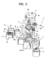
- a head maintenance mechanism 1 comprises: a head cap 2 for capping a nozzle surface of a print head; a wiper 3 for wiping the nozzle surface; and a tube pump 4 as an ink suction pump for sucking ink from the head cap 2. Also, the head maintenance mechanism 1 further comprises a stepping motor 5 as a common drive source for driving the head cap 2, wiper 3, and the tube pump 4. Further, the head maintenance mechanism 1 comprises a power transmitting mechanism 6 for transmitting torque of the stepping motor 5 to the head cap 2, wiper 3, and the tube pump 4. These respective parts are mounted to a housing 7.
- the power transmitting mechanism 6 comprises a cylindrical cam 11, on an outer peripheral surface of which is formed a cam groove 12 having a predetermined depth in a circumferential direction.
- a cap driving pin 13 for movement of the head cap is inserted into the cam groove 12 in a state of being slidable along the cam groove 12 as the cylindrical cam 11 rotates.
- a wiper driving pin 14 for movement of the wiper is inserted in a position offset clockwise substantially 90 degrees into the cam groove 12 in a state of being slidable along the cam groove 12 as the cylindrical cam 11 rotates.
- a pump gear 16 being a drive power input element of the tube pump 4 is coaxially opposed to and disposed immediately below a circular bottom surface 11a of the cylindrical cam 11.
- the tube pump 4 Disposed immediately below the pump gear 16 is the tube pump 4, of which a central shaft 17 extends centrally through the pump gear 16 and the cylindrical cam 11 to project upward.
- the central shaft 17 has its lower end 17a rotatably supported on the housing 7 and its upper end 17b rotatably inserted into a shaft hole 8a formed in an upper wall 8 fixed to an upper surface of the housing by a pair of screws.
- the cylindrical cam 11 and the pump gear 16 are held in frictional engagement by a frictional clutch mechanism 18.
- the frictional clutch mechanism 18 in the embodiment comprises the circular bottom surface 11a, an upper end surface 16a of the pump gear 16, and a coil spring 20 mounted in a central hole 11b of the cylindrical cam 11.
- the coil spring 20 is mounted in a compressed state between the cylindrical cam 11 and the upper wall 8 to constantly push the cylindrical cam 11 with a predetermined bias. Accordingly, the circular bottom surface 11a of the cylindrical cam 11 and the upper end surface 16a of the pump gear 16 are pushed together with a predetermined bias to be made rotatable together by frictional forces generated thereby. When load exceeding the frictional forces acts, sliding is established between both elements.
- the pump gear 16 is connected to the stepping motor 5 through a reduction gear mechanism 19.
- the reduction gear mechanism 19 comprises a composite reduction gear 22 meshing with a motor gear 21 mounted on a motor shaft, and a reduction gear (drive gear) 23 meshing with a small-diameter gear 22a of the composite reduction gear 22, the reduction gear 23 meshing with the pump gear 16.
- the cylindrical cam 11 is formed at an outer peripheral surface of a lower end thereof with an intermittent gear 25, which is formed over an angular range of substantially 200 degrees with teeth 24.
- the teeth 24 can also mesh with the reduction gear 23.
- the cylindrical cam 11 in the embodiment is of finite rotation type, and there are provided rotation limiters for defining a clockwise dead end and a counterclockwise dead end.
- the rotation limiters in the embodiment comprise stopper walls 11d, 11e for defining both ends of an arcuate groove 11c formed over a predetermined angular range along an inner peripheral edge of an annular upper surface of the cylindrical cam 11, and a projection 8b projected into the arcuate groove 11c from the back of the upper wall 8.
- the stopper wall 11d strikes against (contacts) the projection 8b to inhibit rotation of the cylindrical cam 11.
- the other stopper wall 11e strikes against (contacts) the projection 8b to inhibit rotation of the cylindrical cam 11.
- rotation of the stepping motor 5 is transmitted to the pump gear 16 through the reduction gear mechanism 19, and rotation of the pump gear 16 is transmitted to the cylindrical cam 11 through the frictional clutch mechanism 18. Also, rotation of the stepping motor 5 is transmitted directly to the cylindrical cam 11 in a state, in which the intermittent gear 25 of the cylindrical cam 11 meshes with the reduction gear 23.
- the head cap 2 comprises a box-shaped cap body 31 facing a nozzle surface 101 of a print head 100 and opened upward, and a cap holder 32 holding the cap body 31 in a state to receive the same from the upper opening.
- a horizontal arm 32a is projected from a side of the cap holder 32, and the cap driving pin 13 is inserted into a pin hole 32b formed on a tip end of the arm 32a.
- a coil spring 32c inserted into the pin hole 32b constantly biases the cap driving pin 13 in a projecting direction from the pin hole 32b. Accordingly, a tip end of the cap driving pin 13 is constantly pushed against a bottom surface of the cam groove 12 of the cylindrical cam 11.
- An ink absorbing member 33 is housed in the cap body 31, and ink recovered by the ink absorbing member 33 is discharged from an ink discharging port 34 formed in a bottom plate portion of the cap body 31.
- a vent valve mechanism 35 for opening an interior of the cap body to the atmosphere. More specifically, a vent port 36 is extended downward from the bottom plate portion of the cap body 31, and a valve seat 37 is formed on the cap holder 32 to be opposed to a lower end of the vent port 36.
- the cap body 31 is mounted in a state to be vertically movable a predetermined amount with regard to the cap holder 32. Normally, the cap body 31 is biased upward by a coil spring 38, and therefore the vent port 36 is spaced away from the valve seat 37 to be held in an atmospheric opening state.
- a lower end of the vent port 36 abuts against the valve seat 37 to be closed thereby, and so the vent valve mechanism 35 is put in a closed state.
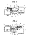
- Fig. 7 the head cap 2 is in a state to be disposed in a retracted position 2A.
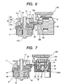
- Figs. 8 and 9 show a state in which the head cap 2 caps the nozzle surface 101.
- the head cap 2 is disposed in an ink sucking position 2B in which capping is effected when the vent valve mechanism 35 is put in a closed state.
- the cap holder 32 rises a distance L1 from the retracted position 2A shown in Fig. 7 while the cap body 31 abuts against the nozzle surface 101 of the print head 100 disposed right above to be relatively pushed downward to have the vent port 36 seated on the valve seat 37.
- the tube pump 4 performs an ink sucking action, ink is sucked from the nozzle orifice on the print head 100 to be discharged outside.
- Fig. 9 shows an idle sucking position 2C, in which the cap holder 32 rises a smaller distance L2 than the distance L1 from the retracted position 2A and the cap body 31 caps the nozzle surface 101, but the vent valve mechanism 35 is remained in a opened state since the lift L2 is small.
- the tube pump 4 performs an ink sucking action, ink is not sucked from the nozzle orifice on the print head 100 and ink recovered by the ink absorbing member 33 is sucked and discharged outside.
- the wiper 3 comprises a rectangular wiper blade 3a, and a blade holder 3b holding the blade, and the blade holder 3b is mounted on the housing 7 in a manner to be able to reciprocate between a retracted position and a wiping position in which the nozzle surface 101 of the print head 100 can be wiped.
- a horizontal arm 3c is extended from a side of the blade holder 3b, and the wiper driving pin 14 is mounted to a tip end of the horizontal arm 3c.
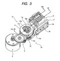
- the tube pump 4 comprises a rotor 42 rotatably inserted into a circular recess 41 formed in the housing 7, the rotor 42 comprising the central shaft 17, a lower end plate 43 formed at a lower end of the shaft 17, and a roller driving disk 44 formed midway up the central shaft 17.
- a pair of rollers 45, 46 are rotatably mounted between the lower end plate 43 and the roller driving disk 44.
- An ink tube 47 is laid between the rollers 45, 46 and an inner peripheral surface 41 a of the circular recess 41 on the housing 7. One end of the ink tube 47 is communicated to the ink discharging port 34 of the head cap 2, and the other end thereof is communicated to an ink recovery section (not shown).
- roller driving disk 44 An upper end surface of the roller driving disk 44 is opposed to a lower end surface of the pump gear 16. Formed at one position in a circumferential direction on both surfaces are engagement projections (not shown), and when the roller driving disk 44 rotates approximately 360 degrees, both projections engage with each other to cause the pump gear 16 and the tube pump 4 to rotate together.
- Arcuate grooves 44a, 44b are formed on the roller driving disk 44 as shown in Figs. 10 and 11 to guide central shafts 45a, 46a of the rollers 45, 46.
- the pair of rollers 45, 46 move radially outward along the arcuate grooves 44a, 44b to revolve while flattening the ink tube 47.
- an ink sucking action prumping action
- a reverse direction shown in Fig. 11 a release state, in which the ink tube 47 is not flattened, is created since the pair of rollers 45, 46 retract radially inward along the arcuate grooves 44a, 44b.
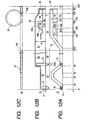
- Fig. 12A shows a development of the cam groove 12 of the cylindrical cam 11 in plan
- Fig. 12B is a view showing groove depths of respective portions
- Fig. 12C is a view showing positions of the intermittent gear 25 and the reduction gear 23.
- the cam groove 12 in the embodiment comprises a first dead end 51, against which the wiper driving pin 14 abuts, or close to which the wiper driving pin is disposed when the cylindrical cam 11 rotates counterclockwise, a wiper driving region 52, which is contiguous to the first dead end 51 and in which the wiper driving pin 14 is moved, a cap driving region 53, in which the cap driving pin 13 is moved, and a second dead end 54 formed at an end of the cap driving region 53.
- the cam groove 12 is formed over an angular range of approximately 350 degrees, and a connecting region 55 connects between the wiper driving region 52 and the cap driving region 53.
- wiper driving region 52 and cap driving region 53 may include discontinuous cam grooves.
- the dead ends of the cylindrical cam 11 in clockwise and counterclockwise rotation are defined by the stopper walls 11d, 11e of the cylindrical cam 11 and the projection 8b formed on the upper wall 8.
- the cylindrical cam 11 rotates clockwise and the stopper wall 11d strikes against the projection 8b, whereby clockwise rotation of the cylindrical cam is stopped.
- the cap driving pin 13 abuts against the second dead end 54 or comes to a position immediate before it abuts against the second dead end 54.
- the cylindrical cam rotates counterclockwise and the stopper wall 11e strikes against the projection 8b, whereby counterclockwise rotation of the cylindrical cam is stopped.
- the wiper driving pin 14 abuts against the first dead end 51 or comes to a position immediate before it abuts against the first dead end 51.
- the wiper driving region 52 comprises a trapezoidal portion extending over an angular range of approximately 90 degrees, and the wiper driving pin 14 disposed at the first dead end 51 slides relative to and along the wiper driving region 52 to move up and down when the cylindrical cam 11 rotates clockwise.
- the wiper 3 comes to the wiping position enabling wiping the nozzle surface 101 from the retracted position, and when the cylindrical cam 11 further rotates approximately 45 degrees, it returns to the retracted position again.
- the wiper driving pin 14 is disposed in the connecting region 55 of the cam groove 12 as shown in Fig. 12A, the wiper 3 rises to the wiping position and then returns to the retracted position when the cylindrical cam rotates counterclockwise.
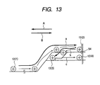
- the cap driving region 53 comprises a slope portion 61 contiguous to the horizontally extending connecting region 55 and slanted upward at a predetermined angle, an upper horizontal portion 62 contiguous to an upper end of the slope portion 61 and extending horizontally, and a lower horizontal portion 63 formed in parallel to and below the upper horizontal portion 62. Also, the cap driving region 53 further comprises a guide portion 64 for guiding the cap driving pin 13, which is disposed at adjacent the second dead end 54 of the upper horizontal portion 62, to the lower horizontal portion 63 when the cylindrical cam 11 rotates counterclockwise.
- a groove depth H1 is deepest in the connecting region 55, the slope portion 61, and the upper horizontal portion 62, while a groove depth of the upper horizontal portion 62 gradually decreases from a portion on a side of the second dead end 54 and is made constant over a portion up to the second dead end 54.
- a groove side of a lower portion of the upper horizontal portion 62 is cut out in a stepwise manner to form a lower horizontal portion 63 having a small groove depth H2.
- the lower horizontal portion 63 extends between the second dead end 54 and the slope portion 61.
- the guide portion 64 is formed by cutting out a bottom surface of the lower horizontal portion 63 while leaving a lower portion 63a, and comprises a portion 64a having a groove depth H3 between groove depths of the portions 62, 63, and a portion 64b, of which groove depth gradually decreases from the portion 64a to the slope portion 61.
- An end of the portion 64a is situated near the portion at which the groove depth of the upper horizontal portion 62 starts decreasing, or the portion at which the groove depth of the upper horizontal portion 62 is decreasing.
- An end of the portion 64b is continuous to the lower horizontal portion 63
- Fig. 13 is a view showing a movement of the cap driving pin 13, which moves along the cap driving region 53 provided with these portions 61 to 64.
- the cap driving pin 13 moves along the slope portion 61 from a position 13(1) in the connecting region 55 as shown by an arrow "a" to be guided into the upper horizontal portion 62 to reach the second dead end 54.
- the teeth 24 of the intermittent gear 25 formed on the cylindrical cam 11 are formed over an angular range from an angular position near the second dead end 54 in the cam groove 12 to an angular position near the slope portion 61 (see Fig. 12C).
- the cylindrical cam 11 rotates clockwise, in a rotating angle position immediate before the cap driving pin 13 moving relative to and along the cam groove 12 abuts against the second dead end 54 of the cam groove 12, one end 24a of the teeth 24 of the intermittent gear 25 passes the reduction gear 23 to be released of meshing with the reduction gear 23.
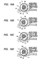
- Figs. 14 to 16 show the positional relationship of respective parts in the initial positions.
- One end 24b of the teeth 24 of the intermittent gear 25 is in a position slightly offset counterclockwise relative to the reduction gear 23.
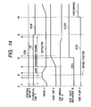
- the wiper driving pin 14 sliding relative to the cam groove 12 slides along the wiper driving region 52 of the cam groove 12 to lift the wiper 3 to the wiping position from the retracted position (from point of time t2 to point of time t4).
- the print head 100 is moved via the position of the wiper 3 to thereby permit the wiper blade 3a to wipe the nozzle surface 101.
- the cap driving pin 13 begins ascending along the slope portion 61 of the cam groove 12.
- the head cap 2 begins ascending from the retracted position 2A.
- the cap body 31 of the head cap 2 is put in a state to cap the nozzle surface 101 of the print head 100 having stood by immediately above, and thereafter only the cap holder 32 ascends and the cap body 31 is relatively depressed downward.
- the vent valve mechanism 35 of the head cap 2 shifts to a closed state at a point of time t6, and thereafter the head cap 2 reaches the ink sucking position 2B. This state is shown in Figs. 8 and 16B.
- Fig. 16C shows this state.
- the pump gear 16 makes substantially one revolution from the initial position, the pump gear 16 engages with the roller driving disk 44 of the tube pump 4 (a point of time t10), and the tube pump 4 is then drivingly rotated clockwise.
- the pair of rollers 45, 46 revolve while flattening the ink tube 47 as shown in Fig. 10, and ink suction is performed in the head cap 2 capped in a state in which the vent valve mechanism 35 is closed.
- ink is sucked from the nozzle orifice on the print head 100 to be discharged outside.
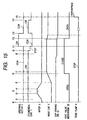
- the cylindrical cam 11 rotates counterclockwise to a position where the wiper driving pin 14 is disposed at the first dead end 51 of the cam groove 12 (state at a point of time t0).
- the stopper wall 11e of the cylindrical cam 11 strikes against the projection 8b of the upper wall 8 to inhibit rotation of the cylindrical cam 11. Accordingly, slip is then generated in the frictional clutch mechanism 18 so that the cylindrical cam 11 is held in that position.
- the rotation of the stepping motor 5 is reversed in a forward direction (clockwise direction) for a predetermined period of time (from the point of time t11 to a point of time t13).
- the cylindrical cam 11 rotates counterclockwise such that the cap driving pin 13 moves within the cam groove 12 along a path indicated by an arrow b in Fig. 13, and reach the lower horizontal portion 63 at the point of time t13.
- the cap holder 32 of the head cap 2 descends, the cap body 31 pressed against the nozzle surface 101 is relatively pushed upward while being kept in the capping state, and the vent valve mechanism 35 having been in a closed state returns to an open state at the point of time t12 immediate before the point of time t13.
- the cylindrical cam 11 rotates clockwise or counterclockwise only in a range of rotating angle prescribed by the stopper walls 11d, 11e, and so can be constantly returned to the initial or reference position. Therefore, unlike the case where a cylindrical cam continuously rotated in the same direction by one direction of a motor is used to drive a head cap, wiper or an ink suction pump, there is no need of providing a detector for detecting the position of a cylindrical cam and the respective parts can be operatively controlled on the basis of the number of steps in the stepping motor 5. As a result, it is possible to realize inexpensive drive control of good controllability.
- the tube pump 4 it is possible to use the tube pump 4 to control an amount of ink as sucked on the basis of the number of steps in the stepping motor 5.
- the tube pump 4 can be switched between a pumping state, in which the rollers 45, 46 revolve while flattening the ink tube 47, and a pump release state, in which the rollers 45, 46 retract from the ink tube 47. Therefore, unlike a head maintenance mechanism, in which an ink suction pump is driven only in rotation in one direction, a state of a pump can be switchingly controlled by forward and rearward rotation of a motor.
- the tube pump 4 since play of about 360 degrees is present between the pump gear 16 and the tube pump 4, the tube pump 4 does not operate when only the capping action and the wiping action from the pump release state are made. Therefore, an unnecessary action of the tube pump 4, that is, the flattening action of the ink tube 47 can be avoided, so that it is possible to maintain durability of the ink tube 47. Also, since the ink tube 47 is not flattened in the capping state, there is obtained an effect that there is no deformation of the ink tube 47.
- the upper horizontal. portion 62 and the lower horizontal portion 63 are formed in the cam groove 12 of the cylindrical cam 11 so that when the cylindrical cam 11 is rotated counterclockwise, the cap driving pin 13 disposed at the upper horizontal portion 62 is guided to the lower horizontal portion 63 through the guide portion 64. Accordingly, a state, in which capping of the head cap 2 is made in a closed state to permit ink to be sucked from the nozzle orifice, and a state, in which capping of the head cap 2 is made in an atmospheric opening state to permit ink to be sucked from the ink absorbing member 33 but not to permit ink to be sucked from the nozzle orifice can be realized without separate provision of a drive mechanism for driving of the vent valve mechanism 35.
- the pump gear 16 and the tube pump 4 are provided below the cylindrical cam 11 in a coaxial manner, so that an installation space therefor, in particular, an installation area in a lateral direction can be considerably reduced so that a very compact head maintenance mechanism can be realized.
- the rotation stop position of the cylindrical cam 11 is prescribed by engagement between the stopper walls 11d, 11e of the cylindrical cam 11 and the projection 8b of the upper wall 8.
- Rotation of the cylindrical cam can be restricted by engagement of the cap driving pin 13 and the second dead end 54 and engagement of the wiper driving pin 14 and the first dead end 51.
- clutch forces are applied on the respective pins 13, 14 to cause movements of the head cap 2 and the wiper 3, so that failure of positioning relative to the print head 100 or the like is liable to occur, and fixing portions (mount portions) of the respective pins 13, 14 are also liable to cause a problem in durability.
- the projection 8b formed on the upper wall 8 fixed to the housing 7 receives forces for stopping the rotation of the cylindrical cam, so that failure of positioning of the head cap 2 and the wiper 3 can be avoided and mount portions of the respective pins 13, 14 cause no problem in durability.
- a stepping motor drives the head cap, wiper and the tube pump in the above embodiment
- the invention can be likewise applied to, for example, the head maintenance mechanism configured to drive only the head cap and the ink suction pump.
- cam groove is a single cam groove extending substantially continuously over an angular range of at most 360 degrees, it can be formed as a cam groove comprising a portion for driving of a wiper and a portion for driving of a head cap, which portions are discontinuous or separate.
- the angular range of the cam groove can be 360 degrees or more.
- the intermittent gear can be used in the above embodiment to smoothly and surely rotate the cylindrical cam even when a large load is applied on the cylindrical cam, it is possible to omit the intermittent gear in the case where load applied on the cylindrical cam is small.
Landscapes
- Ink Jet (AREA)
- Facsimile Heads (AREA)
- Particle Formation And Scattering Control In Inkjet Printers (AREA)
Applications Claiming Priority (2)
| Application Number | Priority Date | Filing Date | Title |
|---|---|---|---|
| JP2001359921A JP4126900B2 (ja) | 2001-11-26 | 2001-11-26 | インクジェットプリンタのヘッドメンテナンス機構 |
| JP2001359921 | 2001-11-26 |
Publications (2)
| Publication Number | Publication Date |
|---|---|
| EP1314564A1 EP1314564A1 (en) | 2003-05-28 |
| EP1314564B1 true EP1314564B1 (en) | 2007-03-07 |
Family
ID=19170828
Family Applications (1)
| Application Number | Title | Priority Date | Filing Date |
|---|---|---|---|
| EP02026399A Expired - Lifetime EP1314564B1 (en) | 2001-11-26 | 2002-11-26 | Head maintenance mechanism for ink jet printer and ink jet printer incorporating the same |
Country Status (8)
| Country | Link |
|---|---|
| US (2) | US6746098B2 (enExample) |
| EP (1) | EP1314564B1 (enExample) |
| JP (1) | JP4126900B2 (enExample) |
| KR (1) | KR100470554B1 (enExample) |
| CN (1) | CN1193883C (enExample) |
| AT (1) | ATE355973T1 (enExample) |
| DE (1) | DE60218604T2 (enExample) |
| ES (1) | ES2281486T3 (enExample) |
Families Citing this family (23)
| Publication number | Priority date | Publication date | Assignee | Title |
|---|---|---|---|---|
| JP4126900B2 (ja) * | 2001-11-26 | 2008-07-30 | セイコーエプソン株式会社 | インクジェットプリンタのヘッドメンテナンス機構 |
| EP1386478B1 (en) * | 2002-03-28 | 2006-11-08 | Brother Kogyo Kabushiki Kaisha | Printing device |
| US7390074B2 (en) * | 2004-05-07 | 2008-06-24 | Natsushita Electric Industrial Co., Ltd. | Methods of and apparatuses for wiping a line head in an ink jet recorder |
| JP2005319649A (ja) * | 2004-05-07 | 2005-11-17 | Seiko Epson Corp | ヘッドメンテナンス装置及びそれを備えたインクジェットプリンタ |
| KR100608060B1 (ko) * | 2004-07-01 | 2006-08-02 | 삼성전자주식회사 | 잉크젯 프린터 |
| JP2006305785A (ja) * | 2005-04-26 | 2006-11-09 | Seiko Epson Corp | ワイピング装置及び液体噴射装置 |
| JP4819394B2 (ja) * | 2005-05-12 | 2011-11-24 | キヤノン株式会社 | 記録ヘッドの吸引方法 |
| JP4899399B2 (ja) * | 2005-09-29 | 2012-03-21 | セイコーエプソン株式会社 | 液体噴射装置におけるクリーニング装置及び液体噴射装置 |
| US7530664B2 (en) | 2005-09-29 | 2009-05-12 | Seiko Epson Corporation | Maintenance device for liquid-ejecting apparatus and liquid-ejecting apparatus |
| JP4947960B2 (ja) * | 2005-11-24 | 2012-06-06 | 株式会社リコー | 吸引ポンプ、維持回復装置及び画像形成装置 |
| JP4853369B2 (ja) | 2006-04-18 | 2012-01-11 | セイコーエプソン株式会社 | 液体噴射装置 |
| US20090047309A1 (en) * | 2007-08-13 | 2009-02-19 | Maes Daniel H | Cosmetic methods and compositions for repairing human skin |
| US8104885B2 (en) * | 2008-01-04 | 2012-01-31 | Eastman Kodak Company | Selector for engagement of printer functions |
| KR200449707Y1 (ko) * | 2008-10-16 | 2010-08-02 | 주식회사 에스피조인트 | 완강기 설치대 |
| US8579419B2 (en) * | 2008-11-13 | 2013-11-12 | Seiko Epson Corporation | Fluid ejecting apparatus |
| JP5187293B2 (ja) * | 2009-09-30 | 2013-04-24 | ブラザー工業株式会社 | 画像記録装置 |
| JP5761495B2 (ja) * | 2011-02-28 | 2015-08-12 | 株式会社ミマキエンジニアリング | クリーニング装置及びこれを備えた液体吐出装置 |
| JP5873560B2 (ja) * | 2011-10-31 | 2016-03-01 | ヒューレット−パッカード デベロップメント カンパニー エル.ピー.Hewlett‐Packard Development Company, L.P. | プリントヘッド用のキャッピング装置 |
| JP6248556B2 (ja) * | 2013-11-07 | 2017-12-20 | セイコーエプソン株式会社 | 液体噴射ヘッドの清掃装置、および、この清掃装置を備えた液体噴射装置 |
| JP6849882B2 (ja) * | 2016-08-01 | 2021-03-31 | キヤノン株式会社 | 記録装置 |
| CN107933092A (zh) * | 2017-12-04 | 2018-04-20 | 新会江裕信息产业有限公司 | 一种喷墨打印机的服务站 |
| JP7046457B2 (ja) * | 2019-03-26 | 2022-04-04 | ローランドディー.ジー.株式会社 | インクジェットプリンタおよびクリーニング用のコンピュータプログラム |
| US11731427B2 (en) | 2019-03-26 | 2023-08-22 | Roland Dg Corporation | Ink jet printer and non-transitory recording medium storing computer program for cleaning |
Family Cites Families (18)
| Publication number | Priority date | Publication date | Assignee | Title |
|---|---|---|---|---|
| JPS61277456A (ja) * | 1985-06-04 | 1986-12-08 | Canon Inc | 液体噴射記録装置における吸引回復装置 |
| JPS6381048A (ja) * | 1986-09-25 | 1988-04-11 | Alps Electric Co Ltd | インクジエツトヘツドのキヤツプ機構 |
| JP2796118B2 (ja) | 1989-04-04 | 1998-09-10 | 株式会社リコー | インクジェットプリンタのインク供給ユニット |
| DE69222994T2 (de) * | 1991-07-31 | 1998-04-02 | Canon Kk | Getriebe für Aufzeichnungsgeräte |
| JP3151328B2 (ja) | 1993-03-12 | 2001-04-03 | シチズン時計株式会社 | インクジェットプリンタの回復装置 |
| JPH09109380A (ja) * | 1995-10-20 | 1997-04-28 | Brother Ind Ltd | インクジェットプリンタ |
| JP3464086B2 (ja) * | 1995-11-16 | 2003-11-05 | ブラザー工業株式会社 | 記録装置における駆動伝達切換機構 |
| US6318835B2 (en) * | 1995-11-20 | 2001-11-20 | Brother Kogyo Kabushiki Kaisha | Ink-jet printer with maintenance mechanism |
| JP3754737B2 (ja) * | 1996-01-10 | 2006-03-15 | キヤノン株式会社 | インクジェット記録装置 |
| EP1167041B1 (en) | 1996-11-22 | 2004-03-03 | Seiko Epson Corporation | Ink jet recording apparatus |
| US6312093B1 (en) * | 1997-11-14 | 2001-11-06 | Canon Kabushiki Kaisha | Ink jet recording apparatus |
| US6220692B1 (en) * | 1998-07-15 | 2001-04-24 | Seiko Epson Corporation | Ink jet recording apparatus |
| JP4187120B2 (ja) | 1998-11-06 | 2008-11-26 | 株式会社フレクストロニクス・デザイン・ジャパン | インクジェットプリンタのヘッドメンテナンス機構 |
| JP2001270126A (ja) | 2000-03-28 | 2001-10-02 | Canon Inc | インクジェット記録装置 |
| JP4681714B2 (ja) | 2000-07-21 | 2011-05-11 | キヤノン株式会社 | インクジェット記録装置 |
| JP2002137408A (ja) | 2000-10-31 | 2002-05-14 | Naltec Inc | サービスステーション装置およびプリンタ |
| US6533387B2 (en) * | 2001-04-11 | 2003-03-18 | Agilent Technologies, Inc. | Inkjet printing system using single motor for print media advance and carriage motion |
| JP4126900B2 (ja) * | 2001-11-26 | 2008-07-30 | セイコーエプソン株式会社 | インクジェットプリンタのヘッドメンテナンス機構 |
-
2001
- 2001-11-26 JP JP2001359921A patent/JP4126900B2/ja not_active Expired - Fee Related
-
2002
- 2002-11-25 US US10/303,087 patent/US6746098B2/en not_active Expired - Fee Related
- 2002-11-26 ES ES02026399T patent/ES2281486T3/es not_active Expired - Lifetime
- 2002-11-26 KR KR10-2002-0073970A patent/KR100470554B1/ko not_active Expired - Fee Related
- 2002-11-26 EP EP02026399A patent/EP1314564B1/en not_active Expired - Lifetime
- 2002-11-26 AT AT02026399T patent/ATE355973T1/de not_active IP Right Cessation
- 2002-11-26 DE DE60218604T patent/DE60218604T2/de not_active Expired - Lifetime
- 2002-11-26 CN CNB021526044A patent/CN1193883C/zh not_active Expired - Fee Related
-
2004
- 2004-04-22 US US10/829,232 patent/US6994418B2/en not_active Expired - Lifetime
Also Published As
| Publication number | Publication date |
|---|---|
| US6746098B2 (en) | 2004-06-08 |
| EP1314564A1 (en) | 2003-05-28 |
| HK1056529A1 (en) | 2004-02-20 |
| DE60218604T2 (de) | 2007-11-22 |
| JP4126900B2 (ja) | 2008-07-30 |
| CN1422749A (zh) | 2003-06-11 |
| US20030107613A1 (en) | 2003-06-12 |
| US20040196327A1 (en) | 2004-10-07 |
| DE60218604D1 (de) | 2007-04-19 |
| ATE355973T1 (de) | 2007-03-15 |
| JP2003154686A (ja) | 2003-05-27 |
| ES2281486T3 (es) | 2007-10-01 |
| US6994418B2 (en) | 2006-02-07 |
| CN1193883C (zh) | 2005-03-23 |
| KR100470554B1 (ko) | 2005-02-21 |
| KR20030043735A (ko) | 2003-06-02 |
Similar Documents
| Publication | Publication Date | Title |
|---|---|---|
| EP1314564B1 (en) | Head maintenance mechanism for ink jet printer and ink jet printer incorporating the same | |
| EP1577095B1 (en) | Cleaning device and ink-jet printer | |
| US8602521B2 (en) | Cap device, maintenance device, and liquid ejecting apparatus | |
| CN100333913C (zh) | 喷液装置 | |
| US7954922B2 (en) | Ink jet recording apparatus | |
| JP4636099B2 (ja) | インクジェットプリンタのヘッドメンテナンス機構 | |
| JP2000085156A (ja) | インクジェット記録装置 | |
| CN101058257B (zh) | 液体喷射装置 | |
| JP4126845B2 (ja) | インクジェットプリンタ | |
| JP2004332914A (ja) | 回転体、駆動変換装置、クリーニング装置及び液体噴射装置 | |
| JP2001341317A (ja) | クリーニング装置及びこれを備えたインクジェットプリンタ | |
| JP2002137408A (ja) | サービスステーション装置およびプリンタ | |
| JP4873089B2 (ja) | クリーニング装置 | |
| JP4631919B2 (ja) | インクジェットプリンタ | |
| JP2007093014A (ja) | 回転体、駆動変換装置、クリーニング装置及びインクジェット式プリンタ | |
| JP2002001977A (ja) | クリーニング装置、ロック装置及びこれらを備えたインクジェットプリンタ | |
| HK1056529B (en) | Printing head maintaining device of ink-jet printer and ink-jet printer fitted with said device | |
| JPH0960578A (ja) | ポンプ | |
| JP4501621B2 (ja) | 液体噴射装置及び液体噴射装置の駆動方法 | |
| JP3382759B2 (ja) | ポンプ及びインクジェット型プリンタ | |
| JP2007055145A (ja) | インクジェットプリンタのヘッドメンテナンス装置 | |
| JP2002001976A (ja) | クリーニング装置及びこれを備えたインクジェットプリンタ | |
| JP2001205883A (ja) | プリンタ | |
| JP2002187287A (ja) | インクジェット式記録装置 | |
| JPH0569551A (ja) | キヤツピング装置 |
Legal Events
| Date | Code | Title | Description |
|---|---|---|---|
| PUAI | Public reference made under article 153(3) epc to a published international application that has entered the european phase |
Free format text: ORIGINAL CODE: 0009012 |
|
| AK | Designated contracting states |
Designated state(s): AT BE BG CH CY CZ DE DK EE ES FI FR GB GR IE IT LI LU MC NL PT SE SK TR |
|
| AX | Request for extension of the european patent |
Extension state: AL LT LV MK RO SI |
|
| 17P | Request for examination filed |
Effective date: 20030904 |
|
| AKX | Designation fees paid |
Designated state(s): AT BE BG CH CY CZ DE DK EE ES FI FR GB GR IE IT LI LU MC NL PT SE SK TR |
|
| GRAP | Despatch of communication of intention to grant a patent |
Free format text: ORIGINAL CODE: EPIDOSNIGR1 |
|
| GRAS | Grant fee paid |
Free format text: ORIGINAL CODE: EPIDOSNIGR3 |
|
| GRAA | (expected) grant |
Free format text: ORIGINAL CODE: 0009210 |
|
| AK | Designated contracting states |
Kind code of ref document: B1 Designated state(s): AT BE BG CH CY CZ DE DK EE ES FI FR GB GR IE IT LI LU MC NL PT SE SK TR |
|
| PG25 | Lapsed in a contracting state [announced via postgrant information from national office to epo] |
Ref country code: AT Free format text: LAPSE BECAUSE OF FAILURE TO SUBMIT A TRANSLATION OF THE DESCRIPTION OR TO PAY THE FEE WITHIN THE PRESCRIBED TIME-LIMIT Effective date: 20070307 Ref country code: BE Free format text: LAPSE BECAUSE OF FAILURE TO SUBMIT A TRANSLATION OF THE DESCRIPTION OR TO PAY THE FEE WITHIN THE PRESCRIBED TIME-LIMIT Effective date: 20070307 Ref country code: FI Free format text: LAPSE BECAUSE OF FAILURE TO SUBMIT A TRANSLATION OF THE DESCRIPTION OR TO PAY THE FEE WITHIN THE PRESCRIBED TIME-LIMIT Effective date: 20070307 |
|
| REG | Reference to a national code |
Ref country code: GB Ref legal event code: FG4D |
|
| REG | Reference to a national code |
Ref country code: CH Ref legal event code: NV Representative=s name: BOVARD AG PATENTANWAELTE Ref country code: CH Ref legal event code: EP |
|
| REF | Corresponds to: |
Ref document number: 60218604 Country of ref document: DE Date of ref document: 20070419 Kind code of ref document: P |
|
| REG | Reference to a national code |
Ref country code: IE Ref legal event code: FG4D |
|
| PG25 | Lapsed in a contracting state [announced via postgrant information from national office to epo] |
Ref country code: SE Free format text: LAPSE BECAUSE OF FAILURE TO SUBMIT A TRANSLATION OF THE DESCRIPTION OR TO PAY THE FEE WITHIN THE PRESCRIBED TIME-LIMIT Effective date: 20070607 |
|
| PG25 | Lapsed in a contracting state [announced via postgrant information from national office to epo] |
Ref country code: PT Free format text: LAPSE BECAUSE OF FAILURE TO SUBMIT A TRANSLATION OF THE DESCRIPTION OR TO PAY THE FEE WITHIN THE PRESCRIBED TIME-LIMIT Effective date: 20070807 |
|
| ET | Fr: translation filed | ||
| REG | Reference to a national code |
Ref country code: ES Ref legal event code: FG2A Ref document number: 2281486 Country of ref document: ES Kind code of ref document: T3 |
|
| PG25 | Lapsed in a contracting state [announced via postgrant information from national office to epo] |
Ref country code: SK Free format text: LAPSE BECAUSE OF FAILURE TO SUBMIT A TRANSLATION OF THE DESCRIPTION OR TO PAY THE FEE WITHIN THE PRESCRIBED TIME-LIMIT Effective date: 20070307 |
|
| PG25 | Lapsed in a contracting state [announced via postgrant information from national office to epo] |
Ref country code: CZ Free format text: LAPSE BECAUSE OF FAILURE TO SUBMIT A TRANSLATION OF THE DESCRIPTION OR TO PAY THE FEE WITHIN THE PRESCRIBED TIME-LIMIT Effective date: 20070307 |
|
| PLBE | No opposition filed within time limit |
Free format text: ORIGINAL CODE: 0009261 |
|
| STAA | Information on the status of an ep patent application or granted ep patent |
Free format text: STATUS: NO OPPOSITION FILED WITHIN TIME LIMIT |
|
| PG25 | Lapsed in a contracting state [announced via postgrant information from national office to epo] |
Ref country code: DK Free format text: LAPSE BECAUSE OF FAILURE TO SUBMIT A TRANSLATION OF THE DESCRIPTION OR TO PAY THE FEE WITHIN THE PRESCRIBED TIME-LIMIT Effective date: 20070307 |
|
| 26N | No opposition filed |
Effective date: 20071210 |
|
| PG25 | Lapsed in a contracting state [announced via postgrant information from national office to epo] |
Ref country code: GR Free format text: LAPSE BECAUSE OF FAILURE TO SUBMIT A TRANSLATION OF THE DESCRIPTION OR TO PAY THE FEE WITHIN THE PRESCRIBED TIME-LIMIT Effective date: 20070608 |
|
| PG25 | Lapsed in a contracting state [announced via postgrant information from national office to epo] |
Ref country code: MC Free format text: LAPSE BECAUSE OF NON-PAYMENT OF DUE FEES Effective date: 20071130 |
|
| PG25 | Lapsed in a contracting state [announced via postgrant information from national office to epo] |
Ref country code: IE Free format text: LAPSE BECAUSE OF NON-PAYMENT OF DUE FEES Effective date: 20071126 |
|
| PG25 | Lapsed in a contracting state [announced via postgrant information from national office to epo] |
Ref country code: EE Free format text: LAPSE BECAUSE OF FAILURE TO SUBMIT A TRANSLATION OF THE DESCRIPTION OR TO PAY THE FEE WITHIN THE PRESCRIBED TIME-LIMIT Effective date: 20070307 |
|
| PG25 | Lapsed in a contracting state [announced via postgrant information from national office to epo] |
Ref country code: CY Free format text: LAPSE BECAUSE OF FAILURE TO SUBMIT A TRANSLATION OF THE DESCRIPTION OR TO PAY THE FEE WITHIN THE PRESCRIBED TIME-LIMIT Effective date: 20070307 |
|
| PG25 | Lapsed in a contracting state [announced via postgrant information from national office to epo] |
Ref country code: BG Free format text: LAPSE BECAUSE OF FAILURE TO SUBMIT A TRANSLATION OF THE DESCRIPTION OR TO PAY THE FEE WITHIN THE PRESCRIBED TIME-LIMIT Effective date: 20070607 Ref country code: LU Free format text: LAPSE BECAUSE OF NON-PAYMENT OF DUE FEES Effective date: 20071126 |
|
| PG25 | Lapsed in a contracting state [announced via postgrant information from national office to epo] |
Ref country code: TR Free format text: LAPSE BECAUSE OF FAILURE TO SUBMIT A TRANSLATION OF THE DESCRIPTION OR TO PAY THE FEE WITHIN THE PRESCRIBED TIME-LIMIT Effective date: 20070307 |
|
| PGFP | Annual fee paid to national office [announced via postgrant information from national office to epo] |
Ref country code: NL Payment date: 20101116 Year of fee payment: 9 |
|
| PGFP | Annual fee paid to national office [announced via postgrant information from national office to epo] |
Ref country code: CH Payment date: 20101112 Year of fee payment: 9 |
|
| REG | Reference to a national code |
Ref country code: CH Ref legal event code: PFA Owner name: SEIKO EPSON CORPORATION Free format text: SEIKO EPSON CORPORATION#4-1, NISHI-SHINJUKU 2-CHOME#SHINJUKU-KU, TOKYO 163-0811 (JP) -TRANSFER TO- SEIKO EPSON CORPORATION#4-1, NISHI-SHINJUKU 2-CHOME#SHINJUKU-KU, TOKYO 163-0811 (JP) |
|
| PGFP | Annual fee paid to national office [announced via postgrant information from national office to epo] |
Ref country code: ES Payment date: 20101126 Year of fee payment: 9 |
|
| REG | Reference to a national code |
Ref country code: NL Ref legal event code: V1 Effective date: 20120601 |
|
| REG | Reference to a national code |
Ref country code: CH Ref legal event code: PL |
|
| PG25 | Lapsed in a contracting state [announced via postgrant information from national office to epo] |
Ref country code: LI Free format text: LAPSE BECAUSE OF NON-PAYMENT OF DUE FEES Effective date: 20111130 Ref country code: CH Free format text: LAPSE BECAUSE OF NON-PAYMENT OF DUE FEES Effective date: 20111130 Ref country code: NL Free format text: LAPSE BECAUSE OF NON-PAYMENT OF DUE FEES Effective date: 20120601 |
|
| REG | Reference to a national code |
Ref country code: ES Ref legal event code: FD2A Effective date: 20131023 |
|
| PG25 | Lapsed in a contracting state [announced via postgrant information from national office to epo] |
Ref country code: ES Free format text: LAPSE BECAUSE OF NON-PAYMENT OF DUE FEES Effective date: 20111127 |
|
| PGFP | Annual fee paid to national office [announced via postgrant information from national office to epo] |
Ref country code: DE Payment date: 20141118 Year of fee payment: 13 Ref country code: FR Payment date: 20141110 Year of fee payment: 13 Ref country code: GB Payment date: 20141126 Year of fee payment: 13 |
|
| PGFP | Annual fee paid to national office [announced via postgrant information from national office to epo] |
Ref country code: IT Payment date: 20141110 Year of fee payment: 13 |
|
| REG | Reference to a national code |
Ref country code: DE Ref legal event code: R119 Ref document number: 60218604 Country of ref document: DE |
|
| GBPC | Gb: european patent ceased through non-payment of renewal fee |
Effective date: 20151126 |
|
| PG25 | Lapsed in a contracting state [announced via postgrant information from national office to epo] |
Ref country code: IT Free format text: LAPSE BECAUSE OF NON-PAYMENT OF DUE FEES Effective date: 20151126 |
|
| REG | Reference to a national code |
Ref country code: FR Ref legal event code: ST Effective date: 20160729 |
|
| PG25 | Lapsed in a contracting state [announced via postgrant information from national office to epo] |
Ref country code: GB Free format text: LAPSE BECAUSE OF NON-PAYMENT OF DUE FEES Effective date: 20151126 Ref country code: DE Free format text: LAPSE BECAUSE OF NON-PAYMENT OF DUE FEES Effective date: 20160601 |
|
| PG25 | Lapsed in a contracting state [announced via postgrant information from national office to epo] |
Ref country code: FR Free format text: LAPSE BECAUSE OF NON-PAYMENT OF DUE FEES Effective date: 20151130 |