EP1314209B1 - Verfahren zum herstellen eines strahlungsemittierenden halbleiterchips auf iii-v-nitridhalbleiter-basis und strahlungsemittierender halbleiterchip - Google Patents
Verfahren zum herstellen eines strahlungsemittierenden halbleiterchips auf iii-v-nitridhalbleiter-basis und strahlungsemittierender halbleiterchip Download PDFInfo
- Publication number
- EP1314209B1 EP1314209B1 EP01967062A EP01967062A EP1314209B1 EP 1314209 B1 EP1314209 B1 EP 1314209B1 EP 01967062 A EP01967062 A EP 01967062A EP 01967062 A EP01967062 A EP 01967062A EP 1314209 B1 EP1314209 B1 EP 1314209B1
- Authority
- EP
- European Patent Office
- Prior art keywords
- layer
- thin
- substrate
- film element
- growth
- Prior art date
- Legal status (The legal status is an assumption and is not a legal conclusion. Google has not performed a legal analysis and makes no representation as to the accuracy of the status listed.)
- Expired - Lifetime
Links
- 239000004065 semiconductor Substances 0.000 title claims description 94
- 239000000463 material Substances 0.000 title claims description 51
- 150000004767 nitrides Chemical class 0.000 title claims description 32
- 238000004519 manufacturing process Methods 0.000 title description 24
- 239000000758 substrate Substances 0.000 claims description 87
- 239000010409 thin film Substances 0.000 claims description 26
- 238000000034 method Methods 0.000 claims description 25
- 238000000407 epitaxy Methods 0.000 claims description 12
- 229910002704 AlGaN Inorganic materials 0.000 claims description 8
- VYPSYNLAJGMNEJ-UHFFFAOYSA-N Silicium dioxide Chemical compound O=[Si]=O VYPSYNLAJGMNEJ-UHFFFAOYSA-N 0.000 claims description 3
- 229910052594 sapphire Inorganic materials 0.000 claims description 3
- 239000010980 sapphire Substances 0.000 claims description 3
- 229910052814 silicon oxide Inorganic materials 0.000 claims description 3
- 229910052581 Si3N4 Inorganic materials 0.000 claims description 2
- HQVNEWCFYHHQES-UHFFFAOYSA-N silicon nitride Chemical compound N12[Si]34N5[Si]62N3[Si]51N64 HQVNEWCFYHHQES-UHFFFAOYSA-N 0.000 claims description 2
- 239000000945 filler Substances 0.000 claims 2
- 239000010410 layer Substances 0.000 description 127
- 230000005855 radiation Effects 0.000 description 8
- 238000011161 development Methods 0.000 description 6
- 230000018109 developmental process Effects 0.000 description 6
- 238000005530 etching Methods 0.000 description 6
- 150000001875 compounds Chemical class 0.000 description 5
- 230000006978 adaptation Effects 0.000 description 4
- 230000015572 biosynthetic process Effects 0.000 description 4
- 239000000203 mixture Substances 0.000 description 4
- 239000012790 adhesive layer Substances 0.000 description 3
- 239000002096 quantum dot Substances 0.000 description 3
- 230000007704 transition Effects 0.000 description 3
- 238000000151 deposition Methods 0.000 description 2
- 230000008021 deposition Effects 0.000 description 2
- 238000002360 preparation method Methods 0.000 description 2
- 229910052710 silicon Inorganic materials 0.000 description 2
- 230000003595 spectral effect Effects 0.000 description 2
- 239000000126 substance Substances 0.000 description 2
- 229910018072 Al 2 O 3 Inorganic materials 0.000 description 1
- 229910001218 Gallium arsenide Inorganic materials 0.000 description 1
- 238000010521 absorption reaction Methods 0.000 description 1
- 239000012876 carrier material Substances 0.000 description 1
- 238000005336 cracking Methods 0.000 description 1
- 239000013078 crystal Substances 0.000 description 1
- 230000001419 dependent effect Effects 0.000 description 1
- 230000005611 electricity Effects 0.000 description 1
- 230000002349 favourable effect Effects 0.000 description 1
- 238000011065 in-situ storage Methods 0.000 description 1
- 230000006911 nucleation Effects 0.000 description 1
- 238000010899 nucleation Methods 0.000 description 1
- 230000008092 positive effect Effects 0.000 description 1
- 239000010703 silicon Substances 0.000 description 1
- 238000003631 wet chemical etching Methods 0.000 description 1
Images
Classifications
-
- B—PERFORMING OPERATIONS; TRANSPORTING
- B82—NANOTECHNOLOGY
- B82Y—SPECIFIC USES OR APPLICATIONS OF NANOSTRUCTURES; MEASUREMENT OR ANALYSIS OF NANOSTRUCTURES; MANUFACTURE OR TREATMENT OF NANOSTRUCTURES
- B82Y20/00—Nanooptics, e.g. quantum optics or photonic crystals
-
- H—ELECTRICITY
- H10—SEMICONDUCTOR DEVICES; ELECTRIC SOLID-STATE DEVICES NOT OTHERWISE PROVIDED FOR
- H10H—INORGANIC LIGHT-EMITTING SEMICONDUCTOR DEVICES HAVING POTENTIAL BARRIERS
- H10H20/00—Individual inorganic light-emitting semiconductor devices having potential barriers, e.g. light-emitting diodes [LED]
- H10H20/01—Manufacture or treatment
- H10H20/011—Manufacture or treatment of bodies, e.g. forming semiconductor layers
- H10H20/013—Manufacture or treatment of bodies, e.g. forming semiconductor layers having light-emitting regions comprising only Group III-V materials
- H10H20/0133—Manufacture or treatment of bodies, e.g. forming semiconductor layers having light-emitting regions comprising only Group III-V materials with a substrate not being Group III-V materials
- H10H20/01335—Manufacture or treatment of bodies, e.g. forming semiconductor layers having light-emitting regions comprising only Group III-V materials with a substrate not being Group III-V materials the light-emitting regions comprising nitride materials
-
- H—ELECTRICITY
- H10—SEMICONDUCTOR DEVICES; ELECTRIC SOLID-STATE DEVICES NOT OTHERWISE PROVIDED FOR
- H10H—INORGANIC LIGHT-EMITTING SEMICONDUCTOR DEVICES HAVING POTENTIAL BARRIERS
- H10H20/00—Individual inorganic light-emitting semiconductor devices having potential barriers, e.g. light-emitting diodes [LED]
- H10H20/01—Manufacture or treatment
- H10H20/011—Manufacture or treatment of bodies, e.g. forming semiconductor layers
- H10H20/013—Manufacture or treatment of bodies, e.g. forming semiconductor layers having light-emitting regions comprising only Group III-V materials
- H10H20/0137—Manufacture or treatment of bodies, e.g. forming semiconductor layers having light-emitting regions comprising only Group III-V materials the light-emitting regions comprising nitride materials
-
- H—ELECTRICITY
- H10—SEMICONDUCTOR DEVICES; ELECTRIC SOLID-STATE DEVICES NOT OTHERWISE PROVIDED FOR
- H10H—INORGANIC LIGHT-EMITTING SEMICONDUCTOR DEVICES HAVING POTENTIAL BARRIERS
- H10H20/00—Individual inorganic light-emitting semiconductor devices having potential barriers, e.g. light-emitting diodes [LED]
- H10H20/01—Manufacture or treatment
- H10H20/011—Manufacture or treatment of bodies, e.g. forming semiconductor layers
- H10H20/018—Bonding of wafers
-
- H—ELECTRICITY
- H01—ELECTRIC ELEMENTS
- H01S—DEVICES USING THE PROCESS OF LIGHT AMPLIFICATION BY STIMULATED EMISSION OF RADIATION [LASER] TO AMPLIFY OR GENERATE LIGHT; DEVICES USING STIMULATED EMISSION OF ELECTROMAGNETIC RADIATION IN WAVE RANGES OTHER THAN OPTICAL
- H01S5/00—Semiconductor lasers
- H01S5/30—Structure or shape of the active region; Materials used for the active region
- H01S5/34—Structure or shape of the active region; Materials used for the active region comprising quantum well or superlattice structures, e.g. single quantum well [SQW] lasers, multiple quantum well [MQW] lasers or graded index separate confinement heterostructure [GRINSCH] lasers
- H01S5/343—Structure or shape of the active region; Materials used for the active region comprising quantum well or superlattice structures, e.g. single quantum well [SQW] lasers, multiple quantum well [MQW] lasers or graded index separate confinement heterostructure [GRINSCH] lasers in AIIIBV compounds, e.g. AlGaAs-laser, InP-based laser
- H01S5/34333—Structure or shape of the active region; Materials used for the active region comprising quantum well or superlattice structures, e.g. single quantum well [SQW] lasers, multiple quantum well [MQW] lasers or graded index separate confinement heterostructure [GRINSCH] lasers in AIIIBV compounds, e.g. AlGaAs-laser, InP-based laser with a well layer based on Ga(In)N or Ga(In)P, e.g. blue laser
Definitions
- the invention relates to a method for producing a radiation-emitting semiconductor chip based on III-V nitride semiconductor material according to the preamble of patent claim 1 and to a radiation-emitting semiconductor chip according to the preamble of patent claim 19.
- GaN-based radiation-emitting semiconductor components are, for example, made US 5,874,747 known.
- Such semiconductor devices include a semiconductor body having a plurality of layers made of GaN or a material based thereon. According to the cited document, the plurality of GaN-based layers are applied to a SiC substrate.
- III-V nitride semiconductor materials include the materials derived from GaN or materials related to GaN and, for example, ternary or quaternary mixed crystals based thereon.
- these include the materials AlN, InN, AlGaN (Al 1-x Ga x N, 0 ⁇ x ⁇ 1), InGaN (In 1-x Ga x N, 0 ⁇ x ⁇ 1), InAlN (In 1-x Al x N, 0 ⁇ x ⁇ 1) and AlInGaN (Al 1-xy In x Ga y N, 0 ⁇ x ⁇ 1, 0 ⁇ y ⁇ 1).
- III-V nitride semiconductor material refers to the group of materials described above. Furthermore, this term includes materials used to form buffer layers in the epitaxial fabrication of layers of the recited material systems.
- GaN-based semiconductor bodies having an intermediate SiC substrate formed on the original epitaxial substrate are known.
- the original substrate body is removed during manufacture.
- SiC substrates themselves are extremely expensive. If parts of the SiC substrate are incorporated in a semiconductor component with each semiconductor body based on III-V nitride semiconductor materials, the costs for the semiconductor component are directly linked to the costs of the SiC substrate. A cost-effective production of the semiconductor device is made difficult.
- SiC substrate in semiconductor chips based on III-V nitride semiconductors can lead to a reduction in the radiation yield, since SiC partially absorbs the radiation emitted by these and thus reduces the proportion of coupled-out radiation.
- These thin substrates are required to prevent cracking in the semiconductor body due to the different thermal expansion coefficients between silicon and III-V nitride semiconductor based materials.
- the radiation-emitting semiconductor chip based on III-V nitride semiconductor material is formed as a thin-film element.
- a thin-film element is understood as meaning a semiconductor layer sequence which consists essentially exclusively of a stack of epitaxial layers based on III-V nitride semiconductor material.
- the thin-film element consists of a plurality of III-V nitride semiconductor epitaxial layers, wherein the semiconductor body is bounded on one side by an n-conducting and on the opposite side by a p-type epitaxial layer.
- the thin-film element is applied with the p-type side on a conductive support having a mounting surface has for the thin-film element and preferably at the same time can be used for contacting the thin-film element.
- contact surface refers to this contact surface without further details.
- the semiconductor chip thus formed no epitaxial substrate usual thickness (> 100 microns), such as a SiC substrate, so that the material costs are lowered for the semiconductor device.
- a further advantage of the thin-film embodiment is that the semiconductor body contains only small residues of a radiation-absorbing substrate or no radiation-absorbing substrate.
- the radiation efficiency can be increased by using a reflective carrier.
- An advantageous development of the invention consists in forming the thin film element on the n-type side limiting epitaxial layer as a conductive buffer layer.
- buffer layers in the fabrication of GaN-based semiconductor bodies is common to compensate for lattice mismatch between the epitaxial substrate and the epitaxial layers following the buffer layer.
- a conductive buffer layer has the great advantage that a vertically conductive semiconductor device can be created with the semiconductor body thus formed.
- the buffer layer is formed in multiple layers.
- the buffer layer is formed in multiple layers.
- the buffer layer consists of AlGaN-based materials, such as Al 1-x Ga x N where 0 ⁇ x ⁇ 1 and Al 1-xy In x Ga y N where 0 ⁇ x ⁇ 1, 0 ⁇ y ⁇ 1 and x + y ⁇ 1.
- the surface finish and the crystalline quality of such low Al content layers are low, it is advantageous to form the contact surface side remote from the high Al content buffer layer.
- the high Al content increases the surface quality of the buffer layer and achieves good adaptation to subsequent III-V nitride semiconductor-based layers.
- a buffer layer with a low Al content on the side of the contact surface and high Al content on the opposite side thus advantageously forms a conductive buffer layer with a high surface quality at the same time.
- the III-V nitride semiconductor-based layers are applied to an epitaxial substrate, the substrate body of which is matched to a III-V nitride semiconductor material or one in comparison to III-V nitride semiconductor materials.
- Nitride semiconductor materials has greater thermal expansion coefficient and that is limited on the epitaxial side of a thin growth layer containing Si (111).
- the thermal expansion of the epitaxial substrate in the production of the III-V nitride semiconductor body is determined by the substrate body, so that the substrate behaves thermally similar to the layers to be applied.
- a Si (111) surface has a hexagonal structure and is thus well suited as an epitaxial surface for III-V nitride semiconductor materials.
- Si (111) surfaces are easy to process and prepare for epitaxy.
- the processing techniques of Si (111) are well known and proven in the semiconductor industry because of the superior use of this material.
- Polycrystalline SiC (PolySiC), GaN or polycrystalline GaN (PolyGaN) is preferably used as the substrate body the good thermal adaptation to GaN-based layers used.
- the substrate body may include sapphire ( ⁇ -Al 2 O 3 ), which has a larger thermal expansion coefficient than III-V nitride semiconductor materials.
- substrate bodies are significantly less expensive than the substrates used according to the prior art, since the semiconductor body is deposited on the surface of the growth layer and thus advantageously the requirements for the crystalline properties of the substrate body are reduced. Due to the reduced requirements in particular inexpensive polycrystalline materials can be used.
- the substrate body is preferably connected to the growth layer by an adhesive layer consisting of silicon oxide or silicon nitride.
- the method is continued after the application of the III-V nitride semiconductor-based layers by applying a carrier to the III-V nitride semiconductor-based layers in a next step.
- the epitaxial substrate is peeled off from the III-V nitride semiconductor-based layers.
- the use of an Si (111) growth layer as the epitaxial surface is advantageous in detaching the epitaxial substrate, since the semiconductor body can easily be detached from the substrate body, for example by etching.
- the Si (111) growth layer represents a sacrificial layer.
- a contact surface is applied after the epitaxial substrate has been detached from the surface of the semiconductor body from which the epitaxial substrate has been detached.
- An advantageous embodiment of the production method according to the invention consists in structuring the majority of the III-V nitride semiconductor layers prior to the detachment of the epitaxial substrate.
- structuring is to be understood as meaning measures which laterally subdivide the epitaxial layers into a multiplicity of individual epitaxial layer stacks arranged side by side on the epitaxial substrate.
- the structuring advantageously brings about an enlargement of the surface exposed to the etching attack.
- an intermediate carrier is first applied to the epitaxial layers based on III-V nitride semiconductor material. Thereafter, in turn, the epitaxial substrate peeled off and a support applied to the side of the epitaxial layers, from which the epitaxial substrate was peeled off. In the next step, the intermediate carrier is replaced.
- the layer sequence of the layers based on III-V nitride semiconductor material with respect to the carrier is advantageously reversed compared to the production method described above.
- This reversal is advantageous in order to be able to also use subsequent methods, in particular in the case of the housing, which require this reverse layer sequence.
- a particularly preferred embodiment of the production method according to the invention consists in applying as the first layer to the epitaxial substrate an electrically conductive buffer layer.
- Such a buffer layer is of particular advantage in order to produce for the following epitaxial layers a surface with optimally adapted lattice structure, which is at the same time well wetted by the subsequent layer materials and thus enables a uniform growth of the subsequent layers.
- the buffer layer is preferably formed from a plurality of individual layers based on AlGaN.
- a high Al buffer layer forms a lattice matched and well wettable surface for other III-V nitride semiconductor based layers, but has low conductivity, while a low Al content buffer layer conducts electricity well, but has lower crystalline quality and surface finish.
- the buffer layer is formed in two steps.
- a plurality of electrically conductive regions are applied to the growth layer of the epitaxial substrate.
- an InGaN-based material such as In 1-x Ga x N where 0 ⁇ x ⁇ 1 and In 1-xy Al x Ga y N where 0 ⁇ x ⁇ 1, 0 ⁇ y ⁇ is suitable as a material for the conductive regions 1 and x + y ⁇ 1, or GaN.
- this plurality of electrically conductive regions is covered with a planarizing filling layer, wherein the interstices between the conductive regions are filled.
- the material suitable for this is particularly an AlGaN compound with a high Al content.
- the buffer layer thus prepared is very well suited for the deposition of further Layers based on III-V nitride semiconductor material and has a high conductivity.
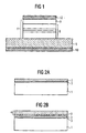
- the in FIG. 1 illustrated radiation-emitting semiconductor chip has a semiconductor body 11 in the form of a thin-film element, which consists of a conductive buffer layer 9 and a layer sequence 8, which contains in particular epitaxial layers based on III-V compound semiconductor material.
- a contact surface 12 is applied, which, unlike in Figure 1, can cover only a portion of the top of the semiconductor body 11 and, for example, have Al or may consist of Al and is designed as a bonding pad.
- the structure of the layer sequence 8 determines the functionality of the semiconductor body 11 or of the chip formed therewith. This layer sequence 8 also includes the radiation generation active layer.
- the semiconductor body 11 has no epitaxial substrate.
- the semiconductor body 11 is n-type and p-type on the opposite side.
- the semiconductor body 11 is deposited on a main surface of a conductive carrier 5.
- the carrier 5 has a second contact surface 10 on the side facing away from the semiconductor body 11.
- the semiconductor chip thus formed vertically, that is perpendicular to the layer planes, consistently conductive. This allows a lateral largely homogeneous current flow through the device and a simple contact.
- lateral scaling is meant the transition to other lateral dimensions of the chip. This transition is easily possible since the chip is not structured in the lateral direction, ie has no topology.
- a conductive buffer layer 9 is a prerequisite for a vertically conductive chip. This layer is formed, for example, from two layers of III-V nitride semiconductor materials. The more detailed nature of the buffer layer 9, together with the preparation of a conductive buffer layer based on FIG. 3 explained.
- the semiconductor bodies formed according to the invention are particularly suitable for realizing light-emitting diode chips with a central wavelength in the yellow, green, green-blue or violet spectral range, light-emitting diodes with particularly high luminosity and for realizing semiconductor lasers an emission wavelength in the green to violet spectral range.
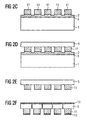
- FIG. 2 is schematically illustrated in six intermediate steps a to f an embodiment of a manufacturing method according to the invention.
- the starting point is a multilayer epitaxial substrate 100 (FIG. FIG. 2a ).
- the substrate body 1 is made of SiC, preferably Polysic.
- an adhesive layer 3 preferably consisting of silicon oxide is formed, which connects the substrate body with a thin growth layer 2, which consists for example of Si (111).
- the thickness of the growth layer 2 is chosen so small that its thermal expansion is essentially determined by the underlying substrate body 1.
- the thickness of the growth layer 2 is between about 0.1 .mu.m and 20 .mu.m, preferably it is less than 10 .mu.m and particularly preferably it is between 0.1 .mu.m and 2 .mu.m.
- a plurality of layers 4 of III-V nitride semiconductor materials are deposited, FIG. 2b ,
- a conductive AlGaN buffer layer 9 is preferably first formed on the surface of the growth layer 2, since GaN itself and InGaN compounds only poorly wet Si (111) or SiC surfaces.
- the buffer layer 9 and the adjacent layers based thereon on the basis of III-V compound semiconductor material are formed n-type.
- the epitaxial layer stack is bounded by one or more p-type layers.
- n-type and p-type layers Between the n-type and p-type layers, a plurality of Al 1-xy Ga x In y N-based layers having 0 ⁇ x ⁇ 1, 0 ⁇ x ⁇ 1 and x + y ⁇ 1 are formed, and the radiation generation is narrower Serve the purpose. Suitable for this purpose are all radiation-generating semiconductor structures known to the person skilled in the art, in particular pn junctions with the formation of a single or double heterostructure as well as single and multiple quantum well structures.
- the Al 1-xy Ga x In y N-based layers are laterally structured in the next step, Figure 2c , so that from these a plurality of separate, on the epitaxial substrate 100 juxtaposed layer stack is formed.
- These layer stacks essentially represent the not yet separated thin-film elements 11 of the radiation-emitting chips.
- the mesa etching takes place into the growth layer 2 of the epitaxial substrate 100 in order to take place in a following Step to allow easy detachment of the thin-film elements 11 of the epitaxial substrate 100.
- a carrier 5 or alternatively an intermediate carrier 13 is applied on the p-conducting side of the thin-film elements 11 remote from the epitaxy substrate 100.
- a carrier material for example, GaAs or Cu can be used.
- the epitaxial substrate 100 is detached from the thin-film element 11.
- the detachment is wet chemical by etching, wherein the growth layer 2 is destroyed.
- the wet chemical detachment with etching of the growth layer 2 requires a much lower cost than, for example, the replacement of a SiC substrate body.
- a carrier 5 is applied using an intermediate carrier 13 after the detachment of the epitaxial substrate 100 in its place, and then the intermediate carrier 13 is removed.
- the buffer layer 9 lies on the side of the semiconductor body facing the carrier 5 ( FIG. 2e , right). In the other case, the buffer layer 9 is formed on the side facing away from the carrier 5 of the semiconductor body 11.
- the semiconductor body 11 and the carrier 5 are provided with contact surfaces 12 and 10, respectively. Subsequently, the carrier 5 is severed between each of the semiconductor bodies 11, so that a plurality of in FIG. 1 illustrated semiconductor chips is formed ( FIG. 2f ).
- the bonding of the thin-film elements 11 to the carrier 5 or the intermediate carrier 13 in conjunction with the subsequent detachment of the epitaxial substrate 100 advantageously allows a further use of the epitaxial substrate body 1, resulting in a significant cost reduction in the case of SiC as a substrate body material.
- the entire substrate can be etched away if its reuse does not provide a particular advantage.
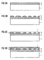
- FIG. 3 schematically illustrates the preparation of a conductive buffer layer 9 with reference to four intermediate steps.
- a SiC or PolySiC substrate body 1 having an epitaxial growth layer 2 containing, for example, Si (III) is used ( FIG. 3a ).
- a nucleation layer 6 in the form of a plurality of quantum dots is deposited ( FIG. 3b ).
- the material used for this is AlGaInN with a low Al content ( ⁇ 50%), InGaN or GaN.
- the quantum dots are highly conductive but do not form a closed layer. Thus arises on the surface of the growth layer, a plurality of mutually non-contiguous, electrically conductive areas. The degree of coverage can vary between 1% and 99% depending on the material composition.
- a planarizing AlGaN-based filling layer 7 with a high Al content for example Al x Ga 1-x N with x> 0.5 ( Figure 3c ) so that a planar structure 9 results.
- the conductive regions 6 form channel-like connections through the buffer layer 9 and ensure good electrical conductivity of the buffer layer 9.
- a layer sequence 8 which in particular contains epitaxial layers based on III-V compound semiconductor material, is deposited on the buffer layer 9 ( Figure 3c ), which essentially determines the functionality of the semiconductor device.
- compositions of the semiconductor materials can be adapted to the requirements and the intended use of the device in the specified frame.
- the central wavelength of the generated radiation can be determined.
Landscapes
- Chemical & Material Sciences (AREA)
- Engineering & Computer Science (AREA)
- Nanotechnology (AREA)
- Physics & Mathematics (AREA)
- Life Sciences & Earth Sciences (AREA)
- Biophysics (AREA)
- Optics & Photonics (AREA)
- Crystallography & Structural Chemistry (AREA)
- Led Devices (AREA)
Applications Claiming Priority (3)
| Application Number | Priority Date | Filing Date | Title |
|---|---|---|---|
| DE10042947A DE10042947A1 (de) | 2000-08-31 | 2000-08-31 | Strahlungsemittierendes Halbleiterbauelement auf GaN-Basis |
| DE10042947 | 2000-08-31 | ||
| PCT/DE2001/003348 WO2002019439A1 (de) | 2000-08-31 | 2001-08-31 | Verfahren zum herstellen eines strahlungsemittierenden halbleiterchips auf iii-v-nitridhalbleiter-basis und strahlungsemittierender halbleiterchip |
Publications (2)
| Publication Number | Publication Date |
|---|---|
| EP1314209A1 EP1314209A1 (de) | 2003-05-28 |
| EP1314209B1 true EP1314209B1 (de) | 2012-10-03 |
Family
ID=7654526
Family Applications (1)
| Application Number | Title | Priority Date | Filing Date |
|---|---|---|---|
| EP01967062A Expired - Lifetime EP1314209B1 (de) | 2000-08-31 | 2001-08-31 | Verfahren zum herstellen eines strahlungsemittierenden halbleiterchips auf iii-v-nitridhalbleiter-basis und strahlungsemittierender halbleiterchip |
Country Status (7)
Families Citing this family (65)
| Publication number | Priority date | Publication date | Assignee | Title |
|---|---|---|---|---|
| DE10051465A1 (de) * | 2000-10-17 | 2002-05-02 | Osram Opto Semiconductors Gmbh | Verfahren zur Herstellung eines Halbleiterbauelements auf GaN-Basis |
| CN1252837C (zh) * | 2000-04-26 | 2006-04-19 | 奥斯兰姆奥普托半导体股份有限两合公司 | 在GaN基板上的发光二极管芯片和用GaN基板上的发光二极管芯片制造发光二极管元件的方法 |
| EP1277240B1 (de) * | 2000-04-26 | 2015-05-20 | OSRAM Opto Semiconductors GmbH | Verfahren zur Herstellung eines lichtmittierenden Halbleiterbauelements |
| TWI292227B (en) * | 2000-05-26 | 2008-01-01 | Osram Opto Semiconductors Gmbh | Light-emitting-dioed-chip with a light-emitting-epitaxy-layer-series based on gan |
| JP4250909B2 (ja) * | 2002-05-20 | 2009-04-08 | ソニー株式会社 | 半導体素子の分離方法および転写方法 |
| GB2388957A (en) * | 2002-05-24 | 2003-11-26 | Imp College Innovations Ltd | Quantum dots for extended wavelength operation |
| US6841802B2 (en) | 2002-06-26 | 2005-01-11 | Oriol, Inc. | Thin film light emitting diode |
| DE10245631B4 (de) * | 2002-09-30 | 2022-01-20 | OSRAM Opto Semiconductors Gesellschaft mit beschränkter Haftung | Halbleiterbauelement |
| TWI243488B (en) | 2003-02-26 | 2005-11-11 | Osram Opto Semiconductors Gmbh | Electrical contact-area for optoelectronic semiconductor-chip and its production method |
| DE10350707B4 (de) * | 2003-02-26 | 2014-02-13 | Osram Opto Semiconductors Gmbh | Elektrischer Kontakt für optoelektronischen Halbleiterchip und Verfahren zu dessen Herstellung |
| EP2264798B1 (en) * | 2003-04-30 | 2020-10-14 | Cree, Inc. | High powered light emitter packages with compact optics |
| US7589003B2 (en) * | 2003-06-13 | 2009-09-15 | Arizona Board Of Regents, Acting For And On Behalf Of Arizona State University, A Corporate Body Organized Under Arizona Law | GeSn alloys and ordered phases with direct tunable bandgaps grown directly on silicon |
| WO2004114368A2 (en) * | 2003-06-13 | 2004-12-29 | Arizona Board Of Regents, A Body Corporate Of The State Of Arizona Acting For And On Behalf Of Arizona State University | METHOD FOR PREPARING GE1-x-ySnxEy (E=P, As, Sb) SEMICONDUCTORS AND RELATED Si-Ge-Sn-E AND Si-Ge-E ANALOGS |
| JP4218597B2 (ja) | 2003-08-08 | 2009-02-04 | 住友電気工業株式会社 | 半導体発光素子の製造方法 |
| JP4110222B2 (ja) | 2003-08-20 | 2008-07-02 | 住友電気工業株式会社 | 発光ダイオード |
| EP1569263B1 (de) | 2004-02-27 | 2011-11-23 | OSRAM Opto Semiconductors GmbH | Verfahren zum Verbinden zweier Wafer |
| US7791061B2 (en) * | 2004-05-18 | 2010-09-07 | Cree, Inc. | External extraction light emitting diode based upon crystallographic faceted surfaces |
| US7332365B2 (en) * | 2004-05-18 | 2008-02-19 | Cree, Inc. | Method for fabricating group-III nitride devices and devices fabricated using method |
| US7534633B2 (en) * | 2004-07-02 | 2009-05-19 | Cree, Inc. | LED with substrate modifications for enhanced light extraction and method of making same |
| US8513686B2 (en) * | 2004-09-22 | 2013-08-20 | Cree, Inc. | High output small area group III nitride LEDs |
| US8174037B2 (en) | 2004-09-22 | 2012-05-08 | Cree, Inc. | High efficiency group III nitride LED with lenticular surface |
| US7259402B2 (en) * | 2004-09-22 | 2007-08-21 | Cree, Inc. | High efficiency group III nitride-silicon carbide light emitting diode |
| US7737459B2 (en) * | 2004-09-22 | 2010-06-15 | Cree, Inc. | High output group III nitride light emitting diodes |
| US8288942B2 (en) * | 2004-12-28 | 2012-10-16 | Cree, Inc. | High efficacy white LED |
| US7932111B2 (en) | 2005-02-23 | 2011-04-26 | Cree, Inc. | Substrate removal process for high light extraction LEDs |
| KR100631980B1 (ko) * | 2005-04-06 | 2006-10-11 | 삼성전기주식회사 | 질화물 반도체 소자 |
| US8575651B2 (en) * | 2005-04-11 | 2013-11-05 | Cree, Inc. | Devices having thick semi-insulating epitaxial gallium nitride layer |
| US8674375B2 (en) * | 2005-07-21 | 2014-03-18 | Cree, Inc. | Roughened high refractive index layer/LED for high light extraction |
| CN1988109B (zh) * | 2005-12-21 | 2012-03-21 | 弗赖贝格化合物原料有限公司 | 生产自支撑iii-n层和自支撑iii-n基底的方法 |
| US20070194342A1 (en) * | 2006-01-12 | 2007-08-23 | Kinzer Daniel M | GaN SEMICONDUCTOR DEVICE AND PROCESS EMPLOYING GaN ON THIN SAPHIRE LAYER ON POLYCRYSTALLINE SILICON CARBIDE |
| JP2009538536A (ja) | 2006-05-26 | 2009-11-05 | クリー エル イー ディー ライティング ソリューションズ インコーポレイテッド | 固体発光デバイス、および、それを製造する方法 |
| EP2029936B1 (en) | 2006-05-31 | 2015-07-29 | Cree, Inc. | Lighting device and method of lighting |
| TW200802941A (en) * | 2006-06-22 | 2008-01-01 | Univ Nat Central | A quantum photoelectric element of antimony compound |
| DE102006060410A1 (de) * | 2006-06-30 | 2008-01-03 | Osram Opto Semiconductors Gmbh | Kantenemittierender Halbleiterlaserchip |
| US7885306B2 (en) | 2006-06-30 | 2011-02-08 | Osram Opto Semiconductors Gmbh | Edge-emitting semiconductor laser chip |
| JP2010502014A (ja) * | 2006-08-23 | 2010-01-21 | クリー エル イー ディー ライティング ソリューションズ インコーポレイテッド | 照明装置、および照明方法 |
| EP2064489B1 (en) * | 2006-09-23 | 2019-01-02 | YLX Incorporated | Brightness enhancement method and apparatus of light emitting diodes |
| EP2095011A1 (en) | 2006-12-04 | 2009-09-02 | Cree Led Lighting Solutions, Inc. | Lighting assembly and lighting method |
| US8337045B2 (en) * | 2006-12-04 | 2012-12-25 | Cree, Inc. | Lighting device and lighting method |
| US8026517B2 (en) * | 2007-05-10 | 2011-09-27 | Industrial Technology Research Institute | Semiconductor structures |
| US20080303033A1 (en) * | 2007-06-05 | 2008-12-11 | Cree, Inc. | Formation of nitride-based optoelectronic and electronic device structures on lattice-matched substrates |
| EP2171502B1 (en) * | 2007-07-17 | 2016-09-14 | Cree, Inc. | Optical elements with internal optical features and methods of fabricating same |
| KR100872678B1 (ko) * | 2007-07-23 | 2008-12-10 | 엘지이노텍 주식회사 | 반도체 발광소자의 제조 방법 |
| JP4148367B1 (ja) | 2007-08-02 | 2008-09-10 | 富山県 | 細胞のスクリーニング方法 |
| US8617997B2 (en) * | 2007-08-21 | 2013-12-31 | Cree, Inc. | Selective wet etching of gold-tin based solder |
| US11114594B2 (en) | 2007-08-24 | 2021-09-07 | Creeled, Inc. | Light emitting device packages using light scattering particles of different size |
| JP5212777B2 (ja) * | 2007-11-28 | 2013-06-19 | スタンレー電気株式会社 | 半導体発光装置及び照明装置 |
| US20110114022A1 (en) * | 2007-12-12 | 2011-05-19 | Veeco Instruments Inc. | Wafer carrier with hub |
| US8021487B2 (en) * | 2007-12-12 | 2011-09-20 | Veeco Instruments Inc. | Wafer carrier with hub |
| US9431589B2 (en) | 2007-12-14 | 2016-08-30 | Cree, Inc. | Textured encapsulant surface in LED packages |
| US9012253B2 (en) | 2009-12-16 | 2015-04-21 | Micron Technology, Inc. | Gallium nitride wafer substrate for solid state lighting devices, and associated systems and methods |
| DE102009060749B4 (de) * | 2009-12-30 | 2021-12-30 | OSRAM Opto Semiconductors Gesellschaft mit beschränkter Haftung | Optoelektronischer Halbleiterchip |
| US8329482B2 (en) | 2010-04-30 | 2012-12-11 | Cree, Inc. | White-emitting LED chips and method for making same |
| US8997832B1 (en) | 2010-11-23 | 2015-04-07 | Western Digital (Fremont), Llc | Method of fabricating micrometer scale components |
| US20130330911A1 (en) * | 2012-06-08 | 2013-12-12 | Yi-Chiau Huang | Method of semiconductor film stabilization |
| US10134727B2 (en) | 2012-09-28 | 2018-11-20 | Intel Corporation | High breakdown voltage III-N depletion mode MOS capacitors |
| US9064709B2 (en) * | 2012-09-28 | 2015-06-23 | Intel Corporation | High breakdown voltage III-N depletion mode MOS capacitors |
| US9911813B2 (en) * | 2012-12-11 | 2018-03-06 | Massachusetts Institute Of Technology | Reducing leakage current in semiconductor devices |
| US8896008B2 (en) | 2013-04-23 | 2014-11-25 | Cree, Inc. | Light emitting diodes having group III nitride surface features defined by a mask and crystal planes |
| DE102014116141B4 (de) | 2014-11-05 | 2022-07-28 | OSRAM Opto Semiconductors Gesellschaft mit beschränkter Haftung | Verfahren zur Herstellung zumindest eines optoelektronischen Halbleiterchips, optoelektronischer Halbleiterchip sowie optoelektronisches Halbleiterbauelement |
| DE102017108385A1 (de) | 2017-04-20 | 2018-10-25 | Osram Opto Semiconductors Gmbh | Laserbarren und Halbleiterlaser sowie Verfahren zur Herstellung von Laserbarren und Halbleiterlasern |
| TWI637481B (zh) | 2017-11-29 | 2018-10-01 | 財團法人工業技術研究院 | 半導體結構、發光裝置及其製造方法 |
| DE102018104785A1 (de) * | 2018-03-02 | 2019-09-05 | Osram Opto Semiconductors Gmbh | Verfahren zur Herstellung einer Mehrzahl von transferierbaren Bauteilen und Bauteilverbund aus Bauteilen |
| DE102018104778A1 (de) * | 2018-03-02 | 2019-09-05 | Osram Opto Semiconductors Gmbh | Bauteilverbund aus optischen Bauteilen, Verfahren zur Herstellung eines Bauteilverbunds und Bauelement mit einem optischen Bauteil |
| CN115347450A (zh) * | 2022-08-22 | 2022-11-15 | 福建慧芯激光科技有限公司 | 一种iii-v族化合物半导体光芯片与硅基电芯片实现晶圆级别集成的方法 |
Family Cites Families (45)
| Publication number | Priority date | Publication date | Assignee | Title |
|---|---|---|---|---|
| JPH0760790B2 (ja) * | 1987-05-13 | 1995-06-28 | シャープ株式会社 | 化合物半導体基板 |
| US4912532A (en) * | 1988-08-26 | 1990-03-27 | Hewlett-Packard Company | Electro-optical device with inverted transparent substrate and method for making same |
| JP2542447B2 (ja) * | 1990-04-13 | 1996-10-09 | 三菱電機株式会社 | 太陽電池およびその製造方法 |
| US5244818A (en) * | 1992-04-08 | 1993-09-14 | Georgia Tech Research Corporation | Processes for lift-off of thin film materials and for the fabrication of three dimensional integrated circuits |
| US5286335A (en) * | 1992-04-08 | 1994-02-15 | Georgia Tech Research Corporation | Processes for lift-off and deposition of thin film materials |
| US5391257A (en) * | 1993-12-10 | 1995-02-21 | Rockwell International Corporation | Method of transferring a thin film to an alternate substrate |
| US5679152A (en) | 1994-01-27 | 1997-10-21 | Advanced Technology Materials, Inc. | Method of making a single crystals Ga*N article |
| JP2669368B2 (ja) * | 1994-03-16 | 1997-10-27 | 日本電気株式会社 | Si基板上化合物半導体積層構造の製造方法 |
| US5585648A (en) * | 1995-02-03 | 1996-12-17 | Tischler; Michael A. | High brightness electroluminescent device, emitting in the green to ultraviolet spectrum, and method of making the same |
| US5670798A (en) * | 1995-03-29 | 1997-09-23 | North Carolina State University | Integrated heterostructures of Group III-V nitride semiconductor materials including epitaxial ohmic contact non-nitride buffer layer and methods of fabricating same |
| US5739554A (en) * | 1995-05-08 | 1998-04-14 | Cree Research, Inc. | Double heterojunction light emitting diode with gallium nitride active layer |
| JP3182346B2 (ja) * | 1995-08-31 | 2001-07-03 | 株式会社東芝 | 青色発光素子及びその製造方法 |
| US5798537A (en) * | 1995-08-31 | 1998-08-25 | Kabushiki Kaisha Toshiba | Blue light-emitting device |
| JP3409958B2 (ja) * | 1995-12-15 | 2003-05-26 | 株式会社東芝 | 半導体発光素子 |
| US5874747A (en) | 1996-02-05 | 1999-02-23 | Advanced Technology Materials, Inc. | High brightness electroluminescent device emitting in the green to ultraviolet spectrum and method of making the same |
| US5985687A (en) * | 1996-04-12 | 1999-11-16 | The Regents Of The University Of California | Method for making cleaved facets for lasers fabricated with gallium nitride and other noncubic materials |
| JPH1022226A (ja) * | 1996-07-05 | 1998-01-23 | Super Silicon Kenkyusho:Kk | エピタキシャルウエハ製造方法及び装置 |
| US5684309A (en) * | 1996-07-11 | 1997-11-04 | North Carolina State University | Stacked quantum well aluminum indium gallium nitride light emitting diodes |
| JP3214367B2 (ja) | 1996-08-12 | 2001-10-02 | 豊田合成株式会社 | 半導体発光素子の製造方法 |
| JPH10215035A (ja) | 1997-01-30 | 1998-08-11 | Toshiba Corp | 化合物半導体素子及びその製造方法 |
| US5880491A (en) * | 1997-01-31 | 1999-03-09 | The United States Of America As Represented By The Secretary Of The Air Force | SiC/111-V-nitride heterostructures on SiC/SiO2 /Si for optoelectronic devices |
| JP3914615B2 (ja) | 1997-08-19 | 2007-05-16 | 住友電気工業株式会社 | 半導体発光素子及びその製造方法 |
| US6033995A (en) * | 1997-09-16 | 2000-03-07 | Trw Inc. | Inverted layer epitaxial liftoff process |
| US6201262B1 (en) * | 1997-10-07 | 2001-03-13 | Cree, Inc. | Group III nitride photonic devices on silicon carbide substrates with conductive buffer interlay structure |
| JP3036495B2 (ja) * | 1997-11-07 | 2000-04-24 | 豊田合成株式会社 | 窒化ガリウム系化合物半導体の製造方法 |
| JPH11145515A (ja) * | 1997-11-10 | 1999-05-28 | Mitsubishi Cable Ind Ltd | GaN系半導体発光素子およびその製造方法 |
| US6599133B2 (en) * | 1997-11-18 | 2003-07-29 | Technologies And Devices International, Inc. | Method for growing III-V compound semiconductor structures with an integral non-continuous quantum dot layer utilizing HVPE techniques |
| JPH11284228A (ja) * | 1998-03-30 | 1999-10-15 | Toyoda Gosei Co Ltd | 半導体素子 |
| JP4126749B2 (ja) * | 1998-04-22 | 2008-07-30 | ソニー株式会社 | 半導体装置の製造方法 |
| JP3525061B2 (ja) * | 1998-09-25 | 2004-05-10 | 株式会社東芝 | 半導体発光素子の製造方法 |
| US6329063B2 (en) * | 1998-12-11 | 2001-12-11 | Nova Crystals, Inc. | Method for producing high quality heteroepitaxial growth using stress engineering and innovative substrates |
| US6744800B1 (en) * | 1998-12-30 | 2004-06-01 | Xerox Corporation | Method and structure for nitride based laser diode arrays on an insulating substrate |
| JP2000208822A (ja) * | 1999-01-11 | 2000-07-28 | Matsushita Electronics Industry Corp | 半導体発光装置 |
| US6328796B1 (en) * | 1999-02-01 | 2001-12-11 | The United States Of America As Represented By The Secretary Of The Navy | Single-crystal material on non-single-crystalline substrate |
| US20010042866A1 (en) * | 1999-02-05 | 2001-11-22 | Carrie Carter Coman | Inxalygazn optical emitters fabricated via substrate removal |
| WO2001006546A2 (en) * | 1999-07-16 | 2001-01-25 | Massachusetts Institute Of Technology | Silicon on iii-v semiconductor bonding for monolithic optoelectronic integration |
| US6214733B1 (en) * | 1999-11-17 | 2001-04-10 | Elo Technologies, Inc. | Process for lift off and handling of thin film materials |
| US6646292B2 (en) * | 1999-12-22 | 2003-11-11 | Lumileds Lighting, U.S., Llc | Semiconductor light emitting device and method |
| US6495867B1 (en) * | 2000-07-26 | 2002-12-17 | Axt, Inc. | InGaN/AlGaN/GaN multilayer buffer for growth of GaN on sapphire |
| US6562648B1 (en) * | 2000-08-23 | 2003-05-13 | Xerox Corporation | Structure and method for separation and transfer of semiconductor thin films onto dissimilar substrate materials |
| US6583034B2 (en) * | 2000-11-22 | 2003-06-24 | Motorola, Inc. | Semiconductor structure including a compliant substrate having a graded monocrystalline layer and methods for fabricating the structure and semiconductor devices including the structure |
| US6498073B2 (en) * | 2001-01-02 | 2002-12-24 | Honeywell International Inc. | Back illuminated imager with enhanced UV to near IR sensitivity |
| US6497763B2 (en) * | 2001-01-19 | 2002-12-24 | The United States Of America As Represented By The Secretary Of The Navy | Electronic device with composite substrate |
| JP4211256B2 (ja) * | 2001-12-28 | 2009-01-21 | セイコーエプソン株式会社 | 半導体集積回路、半導体集積回路の製造方法、電気光学装置、電子機器 |
| US6562127B1 (en) * | 2002-01-16 | 2003-05-13 | The United States Of America As Represented By The Secretary Of The Navy | Method of making mosaic array of thin semiconductor material of large substrates |
-
2000
- 2000-08-31 DE DE10042947A patent/DE10042947A1/de not_active Withdrawn
-
2001
- 2001-08-30 TW TW090121292A patent/TW584971B/zh not_active IP Right Cessation
- 2001-08-31 EP EP01967062A patent/EP1314209B1/de not_active Expired - Lifetime
- 2001-08-31 WO PCT/DE2001/003348 patent/WO2002019439A1/de active Application Filing
- 2001-08-31 JP JP2002524235A patent/JP4177097B2/ja not_active Expired - Lifetime
- 2001-08-31 CN CN018181406A patent/CN1471735B/zh not_active Expired - Lifetime
-
2003
- 2003-02-28 US US10/377,363 patent/US6849878B2/en not_active Expired - Lifetime
-
2004
- 2004-12-20 US US11/017,615 patent/US7105370B2/en not_active Expired - Lifetime
-
2007
- 2007-03-20 JP JP2007072671A patent/JP5183085B2/ja not_active Expired - Lifetime
Also Published As
| Publication number | Publication date |
|---|---|
| DE10042947A1 (de) | 2002-03-21 |
| TW584971B (en) | 2004-04-21 |
| CN1471735A (zh) | 2004-01-28 |
| JP5183085B2 (ja) | 2013-04-17 |
| JP2007201493A (ja) | 2007-08-09 |
| JP4177097B2 (ja) | 2008-11-05 |
| US6849878B2 (en) | 2005-02-01 |
| US20050104083A1 (en) | 2005-05-19 |
| US20030197170A1 (en) | 2003-10-23 |
| JP2004508720A (ja) | 2004-03-18 |
| EP1314209A1 (de) | 2003-05-28 |
| WO2002019439A1 (de) | 2002-03-07 |
| CN1471735B (zh) | 2010-05-26 |
| US7105370B2 (en) | 2006-09-12 |
Similar Documents
| Publication | Publication Date | Title |
|---|---|---|
| EP1314209B1 (de) | Verfahren zum herstellen eines strahlungsemittierenden halbleiterchips auf iii-v-nitridhalbleiter-basis und strahlungsemittierender halbleiterchip | |
| EP1920469B1 (de) | Verfahren zum lateralen zertrennen eines halbleiterwafers und optoelektronisches bauelement | |
| EP0903792B1 (de) | Verfahren zum Herstellen einer Mehrzahl von Halbleiterlasern | |
| EP1920508B1 (de) | Verfahren zum lateralen zertrennen eines halbleiterstapelwafers | |
| EP1327267B1 (de) | Verfahren zur herstellung eines halbleiterbauelements auf gan-basis | |
| DE112006001084B4 (de) | Licht emittierende Bauelemente mit aktiven Schichten, die sich in geöffnete Grübchen erstrecken | |
| DE112004002809B9 (de) | Verfahren zum Herstellen eines strahlungsemittierenden Halbleiterchips und durch dieses Verfahren hergestellter Halbleiterchip | |
| EP3345225B1 (de) | Optoelektronisches halbleiterbauelement und verfahren zu dessen herstellung | |
| DE112005003476T5 (de) | Substratentfernungsprozess für LEDs mit hoher Lichtausbeute | |
| DE102013111496A1 (de) | Verfahren zum Herstellen von optoelektronischen Halbleiterbauelementen und optoelektronisches Halbleiterbauelement | |
| EP2695207A1 (de) | Optoelektronischer halbleiterchip | |
| DE102008050573A1 (de) | Verfahren zur Herstellung eines optoelektronischen Halbleiterbauelements und optoelektronisches Halbleiterbauelement | |
| EP1277240A1 (de) | Strahlungsmittierendes halbleiterbauelement und herstellungsverfahren | |
| EP1636836A1 (de) | Verfahren zum herstellen von halbleiterchips | |
| WO2007124737A1 (de) | Strahlungsemittierender halbleiterkörper mit trägersubstrat und verfahren zur herstellung eines solchen | |
| EP1774599B1 (de) | Verfahren zur herstellung von halbleiterchips in dünnfilmtechnik und halbleiterchip in dünnfilmtechnik | |
| DE10203801A1 (de) | Halbleiterbauelement und Verfahren zu dessen Herstellung | |
| WO2013045181A1 (de) | Verfahren zur herstellung eines optoelektronischen halbleiterchips und optoelektronischer halbleiterchip | |
| EP1299909B1 (de) | LUMINESZENZDIODENCHIP AUF DER BASIS VON InGaN UND VERFAHREN ZU DESSEN HERSTELLUNG | |
| WO2018172205A1 (de) | Optoelektronischer halbleiterchip und verfahren zu dessen herstellung | |
| DE19838810B4 (de) | Verfahren zum Herstellen einer Mehrzahl von Ga(In,Al)N-Leuchtdiodenchips | |
| EP1675189A2 (de) | Verfahren zur Herstellung eines Halbleiterchips | |
| DE102005061346A1 (de) | Optoelektronischer Halbleiterchip | |
| DE102018101558A1 (de) | Verfahren zur Herstellung eines Nitrid-Verbindungshalbleiter-Bauelements | |
| EP1649497B1 (de) | Verfahren zur herstellung einer vielzahl von optoelektronischen halbleiterchips und optoelektronischer halbleiterchip |
Legal Events
| Date | Code | Title | Description |
|---|---|---|---|
| PUAI | Public reference made under article 153(3) epc to a published international application that has entered the european phase |
Free format text: ORIGINAL CODE: 0009012 |
|
| 17P | Request for examination filed |
Effective date: 20030206 |
|
| AK | Designated contracting states |
Designated state(s): AT BE CH CY DE DK ES FI FR GB GR IE IT LI LU MC NL PT SE TR |
|
| RBV | Designated contracting states (corrected) |
Designated state(s): DE FR GB |
|
| RAP1 | Party data changed (applicant data changed or rights of an application transferred) |
Owner name: OSRAM OPTO SEMICONDUCTORS GMBH |
|
| RAP1 | Party data changed (applicant data changed or rights of an application transferred) |
Owner name: OSRAM OPTO SEMICONDUCTORS GMBH |
|
| 17Q | First examination report despatched |
Effective date: 20081219 |
|
| GRAP | Despatch of communication of intention to grant a patent |
Free format text: ORIGINAL CODE: EPIDOSNIGR1 |
|
| GRAS | Grant fee paid |
Free format text: ORIGINAL CODE: EPIDOSNIGR3 |
|
| GRAA | (expected) grant |
Free format text: ORIGINAL CODE: 0009210 |
|
| AK | Designated contracting states |
Kind code of ref document: B1 Designated state(s): DE FR GB |
|
| REG | Reference to a national code |
Ref country code: GB Ref legal event code: FG4D Free format text: NOT ENGLISH |
|
| REG | Reference to a national code |
Ref country code: DE Ref legal event code: R096 Ref document number: 50116180 Country of ref document: DE Effective date: 20121129 |
|
| PLBE | No opposition filed within time limit |
Free format text: ORIGINAL CODE: 0009261 |
|
| STAA | Information on the status of an ep patent application or granted ep patent |
Free format text: STATUS: NO OPPOSITION FILED WITHIN TIME LIMIT |
|
| 26N | No opposition filed |
Effective date: 20130704 |
|
| REG | Reference to a national code |
Ref country code: DE Ref legal event code: R097 Ref document number: 50116180 Country of ref document: DE Effective date: 20130704 |
|
| REG | Reference to a national code |
Ref country code: FR Ref legal event code: PLFP Year of fee payment: 16 |
|
| REG | Reference to a national code |
Ref country code: FR Ref legal event code: PLFP Year of fee payment: 17 |
|
| REG | Reference to a national code |
Ref country code: FR Ref legal event code: PLFP Year of fee payment: 18 |
|
| PGFP | Annual fee paid to national office [announced via postgrant information from national office to epo] |
Ref country code: GB Payment date: 20180822 Year of fee payment: 18 |
|
| GBPC | Gb: european patent ceased through non-payment of renewal fee |
Effective date: 20190831 |
|
| PG25 | Lapsed in a contracting state [announced via postgrant information from national office to epo] |
Ref country code: GB Free format text: LAPSE BECAUSE OF NON-PAYMENT OF DUE FEES Effective date: 20190831 |
|
| PGFP | Annual fee paid to national office [announced via postgrant information from national office to epo] |
Ref country code: FR Payment date: 20200821 Year of fee payment: 20 Ref country code: DE Payment date: 20200819 Year of fee payment: 20 |
|
| REG | Reference to a national code |
Ref country code: DE Ref legal event code: R071 Ref document number: 50116180 Country of ref document: DE |