EP1307395B2 - Überwachungseinrichtung für einen aufzug - Google Patents
Überwachungseinrichtung für einen aufzug Download PDFInfo
- Publication number
- EP1307395B2 EP1307395B2 EP01957667A EP01957667A EP1307395B2 EP 1307395 B2 EP1307395 B2 EP 1307395B2 EP 01957667 A EP01957667 A EP 01957667A EP 01957667 A EP01957667 A EP 01957667A EP 1307395 B2 EP1307395 B2 EP 1307395B2
- Authority
- EP
- European Patent Office
- Prior art keywords
- unit
- passive
- pattern
- active
- bus
- Prior art date
- Legal status (The legal status is an assumption and is not a legal conclusion. Google has not performed a legal analysis and makes no representation as to the accuracy of the status listed.)
- Expired - Lifetime
Links
Images


Classifications
-
- B—PERFORMING OPERATIONS; TRANSPORTING
- B66—HOISTING; LIFTING; HAULING
- B66B—ELEVATORS; ESCALATORS OR MOVING WALKWAYS
- B66B13/00—Doors, gates, or other apparatus controlling access to, or exit from, cages or lift well landings
- B66B13/22—Operation of door or gate contacts
Definitions
- the invention relates to a monitoring device for an elevator, which comprises at least one non-contact operable switching device.
- switching devices In elevator systems, individual actions, for example a ride on a lift, are generally monitored by means of switching devices. Several of such switching devices must have a certain state in order to perform the intended action safely. In particular, in the case of an elevator installation it must be ensured that all doors remain closed and mechanically locked before the start of and during the journey of the elevator cage.
- EP 0 535 205 B1 is a monitoring device for a safety chain having a control device is known, which is provided with a non-contact triggerable sensor comprising a switching device. By approaching or removing a magnet, the switches or sensors are actuated.
- a disadvantage of this solution is the fact that the switch or the sensor responds to each magnet, regardless of whether this magnet is the right and the particular of the selected switch or sensor magnet. It is sufficient to approximate a corresponding material to trigger a valid signal. As soon as the switch is within the working range of the magnet, it triggers a valid signal. A malfunction (incorrect triggering) of the switch or the sensor can hardly be excluded with reasonable effort. An erroneous trip can also be caused for example by artifacts and / or external interference, which is dangerous for the safe operation of the elevator system.
- the invention has for its object to provide a monitoring device for an elevator of the type mentioned, which does not have the aforementioned disadvantages and allows safe and trouble-free monitoring. Furthermore, the monitoring device is insensitive to artifacts and external manipulations. By means of the monitoring device, the components to be monitored are uniquely identifiable.
- One advantage is the fact that a valid signal can only be triggered with an example worldwide only passive unit.
- the active unit can not generate a valid signal without having the right passive unit in range.
- Another advantage is that the monitoring is ensured with inexpensive producible elements.
- Another advantage is that several switching devices can be monitored for functionality and condition at the same time.
- the concatenation of several active units takes place in such a way that the answers of all passive units are linked in such a way that a mutual influence in the sense of a misinterpretation can be excluded.
- Another advantage is the fact that a data exchange between active and passive unit can take place only by approaching the working as an antenna coils.
- the passive unit does not need its own power supply or battery. This is achieved by having an energy store in which the energy transmitted by the active unit can be stored. This saves energy. Since the energy must be transmitted to generate the response, no spontaneous activity is possible.
- FIG. 1 a switching device 1 of an electronic security chain is shown, wherein the switching device 1 has formed as an inquiry unit 2 active unit and designed as a response unit 3 passive unit.
- the response unit 3 may be, for example, a transponder, a tag, a smart card or a chip card.
- the interrogation unit 2 has a first coil 4 and the response unit 3 has a second coil 5.
- the query unit 2 and the response unit 3 are in a so-called resting state, that is, they are distanced from each other so far that no interaction so no electromagnetic coupling takes place between them.
- the interrogation unit 2 generates a pattern M which is transmitted to the response unit 3 and to which the response unit 3 does not respond.
- FIG. 2 is the same switching device 1 off FIG. 1 shown, but in this case is in a so-called operating state.
- the interrogation unit 2 and the response unit 3 are arranged so close to each other that an interaction takes place. So there is an electromagnetic coupling between the interrogation unit 2 and the response unit 3 instead.
- On the generated by the query unit 2 pattern M is given by the response unit 3, a complex response M '.
- the interrogation unit 2 may comprise a generator 6, a first modulator 7 and a first demodulator 8.
- the generator 6 may be, for example, an RF generator, an RF generator and so on.
- the response unit 3 may in turn comprise a second modulator 9 and a second demodulator 10.
- the response unit 3 may further comprise an energy store 11, which may be formed, for example, as a capacitor with a capacity. The response unit 3 therefore preferably has no own power supply or battery.
- the interrogation unit 2 is designed so that it is able to transmit information to the response unit 3 and / or to obtain information from the response unit 3.
- the first coil 4 and the second coil 5 are formed in this example as an antenna.
- the interrogation unit 2 transmits the energy to the response unit 3 via an electromagnetic field. Electromagnetic coupling is referred to as the energy transfer functions similarly as in a transformer where the energy from the primary winding is transferred by tight coupling to the secondary winding.
- the energy coupled in via the electromagnetic field temporarily stores the response unit 3 in the energy store 11. As soon as the response unit 3 has received sufficient energy, it becomes functional and responds in a very specific manner to the pattern M generated by the interrogation unit 2.
- the pattern M and / or the answer M ' may be, for example, numbers represented by a bit pattern / bit sequence.
- the pattern M exciting the response unit 3 does not need to be very complex, since it serves primarily to transmit energy and to trigger a response M '.
- the pattern M may be approximately an RF carrier and generated as a phase modulated RF signal.
- the pattern M is used by the response unit 3 only for power generation and synchronization of a response.
- the pattern M as an instruction to the response unit 3 can be understood to generate a corresponding response M '.
- the pattern M need not be constant and may be specified by the interrogation unit 2 or externally.
- the response unit 3 changes the pattern M so as to ensure that this change is made by the corresponding response unit 3 itself and not by another element. This can be done, for example, by the response unit 3 responding to a request with the transmission of a one-to-one number. Thus, the response unit 3 is uniquely identified.
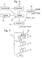
- FIG. 3 shows a concatenation of several switching devices 1, which are serially linked to a central control unit 12.
- the central control unit 12 sends a command r (x) and an instruction a (w) in data word format via a serial channel 13 to all query units 2 of the safety chain S. From this an electromagnetic signal is generated and as a pattern M, for example, with the function M (R, x) can be represented, the response units 3 transmitted.
- the pattern M excites the respective response units 3 if they are in range / within the range of the interrogation units 2.
- Each response unit 3 has a characteristic function fi (x), where i represents the number of participants, that is, in this example, the response units 3 are denoted by the characteristic functions f0 (x), f1 (x) and f2 (x).
- the response units 3 process the pattern M with the respective characteristic functions fi (x).
- the respective responses M 'formed as electromagnetic information, which can be represented by the function M' (A, fi (x)), for example, are converted into data word information and additively linked along the serial channel 13.
- the result a (w + fi (x)) is returned to the central control unit 12. This checks the result for validity and thus decides on the state of the safety chain S, ie on the state of the individual switching devices 1.
- the central control unit 12 must be functional and reliable, which can be ensured for example by a redundant decision branch, not shown in a known manner .
- the answers M 'of the response units 3 can be additively linked, ensuring that the responses of all the switching devices 1 are independent of one another. In this example, this is achieved by the characteristic functions f0 (x), f1 (x) and f2 (x).
- the communication with the central control unit 12 and the data transfer to the same takes place via a bus 13.
- the characteristic function fi (x) of the response unit 3 is stored, for example, in a table. This means that the determination of the function value is attributed to reading out a memory addressed by the function argument.
- the structure of the table can be done in a one-time initialization cycle.
- FIGS. 4, 5 and 6 A preferred embodiment results from an arrangement as in the following FIGS. 4, 5 and 6 is set forth.
- the response unit 3 has an address / data memory 14, an intermediate data memory 15, a local control unit 16, a modulation / demodulation unit 17 and an antenna 18, which may be formed as a coil ,
- the pattern M may be represented by the function M (R, x), where R represents a request and x represents an address. If a pattern M (R, x) is received by the antenna 18 and subsequently demodulated by the modulation / demodulation unit 17, this is communicated as a request R to a local control unit 16. This then causes the reading of the cell with the address x from the address / data memory. The read-out value is interpreted as the result fi (x), modulated together with the identifier A and emitted via the antenna 18 as a response M ', which can thus be represented as a function M' (A, fi (x)).
- the configuration of the address / data memory so that the contents at the addresses x correspond to the values f (x) can also be effected via analogous mechanisms with corresponding commands or else separately, for example by means of a laser and a permanent change in the semiconductor structure.
- the linking of the answers M 'of several response units is carried out by serial addition of the individual results along a bus 13.
- the queries of the response units 3 can be triggered using appropriate commands.
- the interrogation unit 2 has a further antenna 19, a further modulation / demodulation unit 20, a further local control unit 21, a further intermediate data memory 22, an adder 23, and a bus coupling 24, which is positioned along the serial bus 13.
- the result determined by the summation over all tags is compared with that determined by the interrogation unit, and if the safety circuit matches, it is evaluated as closed.
- the central control unit 12 has a control unit 25, a random number generator 26, a memory 27, a computer 28, a comparator 29 and a coupling 30, which ensures the serial connection to the interrogation units 2.
- a random argument x is generated by the random number generator 26 and output to the interrogation units 2 as a command r (x).
- the random argument x will then correspond to an address of the address / data memory 14 of the response unit 3.
- the "desired value” f.sub.10 (x) +... + F.sub.N (x) is calculated. In doing so, all those response units T0... TN which are necessary to achieve a certain security state are taken into account.
- the query of the results by means of the statement a (0).
- the result f0 (x) +... + FN (x) thus determined is compared in the comparator 29 with the desired value and, according to the result, either the "closed circuit" or "open circuit” directive is output.
- An assessment of the safety status can be cyclical or on request.
- f (x) can also be used.
- f is chosen so that a simple criterion can be used to test the result.
- Such functions are well known by the term "one-way function” or "trap door function" in the field of cryptography. The function does not necessarily have to deliver scalar results.
- bus system For communication a variety of known bus system can be used. Since the security is ensured at a higher hierarchical level, the requirements for the bus system itself are very low.
- the concatenation of the interrogation stations can also be accomplished by other functions than the addition.
- a query command r (x) which is propagated along the bus 13 by means of the interrogation units 2, is output by the central control unit 12.
- the query command r (x) serves to generate a response in the response units 3 for each request unit 2, as it were, as a drive command.
- the response units 3 in the series have the characteristic functions f0 (x), f1 (x) and f2 (x).
- the central control unit also sends the instruction a (w) on the bus 13, which is interpreted as a read-out command by the interrogation units 2, to read the answers M 'and forward them.
- w1 a (w0 + f0 (x)
- FIG. 7 is the concatenation according to FIG. 3 shown as a safety chain for the door contacts of a lift system.
- On three floors 31 of a building elevator doors 32 are provided, which are formed in this example as shaft doors 32.
- Each landing door 32 has a first door 32 'and a second door 32 "movable relative to each other for opening and closing the door FIG. 4 represented by the arrows P.
- the first door 32 ' has the interrogation unit 2 and the second door 32 "includes the answering unit 3.
- the interrogation unit 2 and the answering unit 3 are arranged on the respective door 32', 32" so as to be so close when the landing door 32 is closed
- the interrogation units 2 and the response units 3 are preferably located on those parts of the respective door wings that overlap when the door is closed.
- the interrogation units 2 and the answering units 3 are preferably arranged on the corresponding door wings 32 ', 32 "such that they do not interact within the meaning of the invention until the door wings 32', 32" are already mechanically or electromechanically locked.
- the interrogation units 2 of each landing door 32 are connected in series via a bus line 13 and to a control unit 12.
- the query of the interrogation units 2, the answer of the answering units 3 as well as the data transmission to the control unit 12 functions exactly as in FIG. 3 is shown.
- this safety chain S operating in the manner according to the invention, the door contacts of the shaft doors can be safely monitored and uniquely identified. Wrong trips are avoided.
- the control unit 12 continuously monitors the state of the door contacts and is connected to a central elevator control, not shown, in a conventional manner.
- the monitoring device according to the invention can be used at all points of a lift to be secured, and the switching devices can replace all safety switches of a lift.
- the active and / or the passive unit can also be provided with switching contacts or with semiconductor switches, for example, put the energy storage or the antenna out of operation. This could be applied, for example, to existing mechanical contacts.
Landscapes
- Indicating And Signalling Devices For Elevators (AREA)
- Maintenance And Inspection Apparatuses For Elevators (AREA)
- Elevator Control (AREA)
- Elevator Door Apparatuses (AREA)
- Lock And Its Accessories (AREA)
- Train Traffic Observation, Control, And Security (AREA)
- Burglar Alarm Systems (AREA)
- Warehouses Or Storage Devices (AREA)
Priority Applications (2)
| Application Number | Priority Date | Filing Date | Title |
|---|---|---|---|
| EP01957667A EP1307395B2 (de) | 2000-08-07 | 2001-08-02 | Überwachungseinrichtung für einen aufzug |
| CY20071100157T CY1105988T1 (el) | 2000-08-07 | 2007-02-05 | Εξοπλισμος επιτηρησης δια εναν ανελκυστηρα |
Applications Claiming Priority (4)
| Application Number | Priority Date | Filing Date | Title |
|---|---|---|---|
| EP00810706 | 2000-08-07 | ||
| EP00810706 | 2000-08-07 | ||
| PCT/CH2001/000474 WO2002012109A1 (de) | 2000-08-07 | 2001-08-02 | Überwachungseinrichtung für einen aufzug |
| EP01957667A EP1307395B2 (de) | 2000-08-07 | 2001-08-02 | Überwachungseinrichtung für einen aufzug |
Publications (3)
| Publication Number | Publication Date |
|---|---|
| EP1307395A1 EP1307395A1 (de) | 2003-05-07 |
| EP1307395B1 EP1307395B1 (de) | 2006-11-08 |
| EP1307395B2 true EP1307395B2 (de) | 2009-11-18 |
Family
ID=8174850
Family Applications (1)
| Application Number | Title | Priority Date | Filing Date |
|---|---|---|---|
| EP01957667A Expired - Lifetime EP1307395B2 (de) | 2000-08-07 | 2001-08-02 | Überwachungseinrichtung für einen aufzug |
Country Status (14)
| Country | Link |
|---|---|
| US (1) | US6732839B2 (es) |
| EP (1) | EP1307395B2 (es) |
| JP (1) | JP2004505868A (es) |
| CN (1) | CN1232436C (es) |
| AT (1) | ATE344778T1 (es) |
| AU (2) | AU7953101A (es) |
| CA (1) | CA2416902C (es) |
| CY (1) | CY1105988T1 (es) |
| DE (1) | DE50111416D1 (es) |
| DK (1) | DK1307395T3 (es) |
| ES (1) | ES2276809T5 (es) |
| IL (1) | IL153936A0 (es) |
| PT (1) | PT1307395E (es) |
| WO (1) | WO2002012109A1 (es) |
Families Citing this family (30)
| Publication number | Priority date | Publication date | Assignee | Title |
|---|---|---|---|---|
| EP1289870B1 (de) * | 2000-06-13 | 2006-06-07 | Cedes AG | Sicherheitseinrichtung für aufzugstüren |
| US7191165B2 (en) * | 2001-06-04 | 2007-03-13 | Synopsys, Inc. | Transaction based design verification with hierarchical verification components |
| WO2003080495A1 (de) * | 2002-03-27 | 2003-10-02 | Inventio Ag | Schachtüberwachungssystem für aufzug |
| JP4527362B2 (ja) * | 2002-05-03 | 2010-08-18 | インベンテイオ・アクテイエンゲゼルシヤフト | エレベータ装置のシャフトドア監視方法 |
| FR2841075B1 (fr) * | 2002-06-13 | 2004-12-24 | Systemig Sa | Dispositif de controle et/ou de surveillance utilisant au moins un controleur de transmission |
| FR2841084B1 (fr) * | 2002-06-13 | 2004-12-17 | Systemig Sa | Dispositif de telereleve d'etats, et applications |
| JP4205057B2 (ja) | 2002-08-01 | 2009-01-07 | オーチス エレベータ カンパニー | 無線周波数識別装置(RFIDs)を用いたエレベータ |
| EP1418149B1 (en) * | 2002-11-08 | 2011-07-06 | Daniel Schürmann | Elevator door safety device |
| ES2280742T3 (es) * | 2003-04-30 | 2007-09-16 | Thyssenkrupp Elevator Ag | Instalacion de ascensor y procedimiento para el control de una instalacion de ascensor. |
| WO2005052842A2 (en) * | 2003-10-31 | 2005-06-09 | Otis Elevator Company | Rf id and low resolution ccd sensor based positioning system |
| US20080271957A1 (en) * | 2004-06-21 | 2008-11-06 | Siewert Bryan R | Elevator Door Coupler |
| EP1765713A4 (en) * | 2004-06-22 | 2010-03-03 | Otis Elevator Co | ELEVATOR DOOR POSITION DETECTOR |
| ATE521563T1 (de) * | 2004-07-06 | 2011-09-15 | Otis Elevator Co | Elektromagnetisch betriebenes aufzugtürschloss |
| CN100522780C (zh) * | 2004-08-31 | 2009-08-05 | 三菱电机株式会社 | 单井道多轿厢方式电梯的控制装置 |
| ATE532736T1 (de) * | 2004-09-03 | 2011-11-15 | Otis Elevator Co | Aufzug mit einer vorrichtung zur erfassung von fremdkörpern und insbesondere fingern zwischen den türen und den angrenzenden wänden einer aufzugskabine mit glastüren |
| WO2006041450A2 (en) * | 2004-09-23 | 2006-04-20 | Otis Elevator Company | Elevator door lock |
| WO2006036146A1 (en) * | 2004-09-27 | 2006-04-06 | Otis Elevator Company | Elevator door lock sensor device |
| US7896137B2 (en) * | 2005-04-01 | 2011-03-01 | Mitsubishi Electric Corporation | Elevator power system having plural storage apparatuses |
| DE102006013578B4 (de) * | 2006-03-22 | 2008-03-27 | Phoenix Contact Gmbh & Co. Kg | Verfahren und Steuer- und Datenübertragungsanlage zum Überprüfen des Einbauortes eines sicheren Kommunikationsteilnehmers |
| JP4820905B2 (ja) * | 2006-09-12 | 2011-11-24 | オーチス エレベータ カンパニー | 自動ドアの動きを制御するセンサを備えるドアアセンブリ |
| US7958970B2 (en) * | 2009-09-02 | 2011-06-14 | Empire Technology Development Llc | Acceleration sensor calibrated hoist positioning |
| KR101481568B1 (ko) | 2010-09-13 | 2015-01-13 | 오티스 엘리베이터 컴파니 | 엘리베이터 안전 시스템 및 방법 |
| MY166669A (en) * | 2011-08-11 | 2018-07-18 | Inventio Ag | Function-monitoring of a safety element |
| EP2567928B1 (de) * | 2011-09-06 | 2013-09-11 | Cedes AG | Sensor, Sicherungsvorrichtung sowie Aufzugvorrichtung |
| FI123145B (fi) * | 2012-01-23 | 2012-11-30 | Kone Corp | Menetelmä ja järjestely kuljetusjärjestelmän toimintakunnon valvomiseksi |
| TWI622548B (zh) | 2012-12-13 | 2018-05-01 | 伊文修股份有限公司 | 用於人員輸送設備的監視裝置、人員輸送設備、以及用於監視人員輸送設備之方法 |
| SG11201508848YA (en) * | 2013-05-28 | 2015-11-27 | Inventio Ag | Elevator door with a door contact switch |
| US11175638B2 (en) | 2015-11-09 | 2021-11-16 | Otis Elevator Company | Self-diagnostic electrical circuit |
| CN109071164B (zh) * | 2016-05-04 | 2020-06-09 | 因温特奥股份公司 | 包括中央控制单元和多个具有优化的故障识别方法的现场设备的人员运送设备 |
| EP3681833B1 (de) * | 2017-09-13 | 2021-11-03 | Inventio AG | Statusüberprüfung von feldgeräten einer gebäudegebundenen personenbeförderungsanlage |
Citations (4)
| Publication number | Priority date | Publication date | Assignee | Title |
|---|---|---|---|---|
| US3859624A (en) † | 1972-09-05 | 1975-01-07 | Thomas A Kriofsky | Inductively coupled transmitter-responder arrangement |
| DE4032033A1 (de) † | 1990-10-09 | 1992-04-16 | Siemens Ag | Steuerungs- und ueberwachungsverfahren und elektrisches automatisierungssystem fuer eine technische anlage, insbesondere eine schachtanlage |
| US5682024A (en) † | 1995-07-31 | 1997-10-28 | Otis Elevator Company | Elevator position determination |
| WO1998045764A1 (de) † | 1997-04-07 | 1998-10-15 | Euchner Gmbh & Co. | Sicherheitsschalter |
Family Cites Families (20)
| Publication number | Priority date | Publication date | Assignee | Title |
|---|---|---|---|---|
| US3054475A (en) * | 1956-12-18 | 1962-09-18 | Schweiz Wagons Aufzuegefab | Safety device for an elevator door |
| JPS6232496U (es) * | 1985-08-06 | 1987-02-26 | ||
| NL8701565A (nl) * | 1987-07-03 | 1989-02-01 | Nedap Nv | Identificatiesysteem met twee werkingsmodes. |
| US5107964A (en) * | 1990-05-07 | 1992-04-28 | Otis Elevator Company | Separate elevator door chain |
| DE4112626A1 (de) * | 1991-04-18 | 1992-10-22 | Fraunhofer Ges Forschung | Ueberwachungseinrichtung fuer eine steuervorrichtung |
| US5300875A (en) * | 1992-06-08 | 1994-04-05 | Micron Technology, Inc. | Passive (non-contact) recharging of secondary battery cell(s) powering RFID transponder tags |
| JPH0761726A (ja) * | 1993-08-23 | 1995-03-07 | Shimizu Corp | 仮設エレベーター用呼出表示装置 |
| US5708416A (en) * | 1995-04-28 | 1998-01-13 | Otis Elevator Company | Wireless detection or control arrangement for escalator or moving walk |
| JPH1045344A (ja) * | 1996-08-05 | 1998-02-17 | Toshiba Corp | エレベーターの群管理装置 |
| JP3465869B2 (ja) * | 1997-04-11 | 2003-11-10 | ニッタン株式会社 | 異常検知装置および異常監視システム |
| WO1998048523A2 (en) * | 1997-04-24 | 1998-10-29 | Koninklijke Philips Electronics N.V. | Transponder constructed for contactless inductive communication |
| DE19737464A1 (de) * | 1997-08-28 | 1999-03-04 | Datasec Electronic Gmbh | Berührungslos betätigbare Schalteinheit |
| US5945920A (en) * | 1997-12-10 | 1999-08-31 | Atmel Corporation | Minimum voltage radio frequency indentification |
| FI109468B (fi) * | 1998-11-05 | 2002-08-15 | Kone Corp | Vetopyörähissi |
| US6173814B1 (en) * | 1999-03-04 | 2001-01-16 | Otis Elevator Company | Electronic safety system for elevators having a dual redundant safety bus |
| JP3864647B2 (ja) * | 1999-11-26 | 2007-01-10 | 株式会社日立製作所 | エレベータシステム |
| JP3857508B2 (ja) * | 2000-08-29 | 2006-12-13 | 株式会社日立製作所 | エレベータ装置 |
| DE10108772A1 (de) * | 2001-02-23 | 2002-11-21 | Otis Elevator Co | Aufzugssicherheitseinrichtung |
| US6601679B2 (en) * | 2001-09-05 | 2003-08-05 | Otis Elevator Company | Two-part wireless communications system for elevator hallway fixtures |
| US20030089558A1 (en) * | 2001-11-09 | 2003-05-15 | Otis Elevator Company | Power line carrier used in elevator system |
-
2001
- 2001-08-02 AU AU7953101A patent/AU7953101A/xx active Pending
- 2001-08-02 IL IL15393601A patent/IL153936A0/xx not_active IP Right Cessation
- 2001-08-02 CA CA2416902A patent/CA2416902C/en not_active Expired - Lifetime
- 2001-08-02 AT AT01957667T patent/ATE344778T1/de not_active IP Right Cessation
- 2001-08-02 DE DE50111416T patent/DE50111416D1/de not_active Expired - Lifetime
- 2001-08-02 WO PCT/CH2001/000474 patent/WO2002012109A1/de active IP Right Grant
- 2001-08-02 AU AU2001279531A patent/AU2001279531B2/en not_active Ceased
- 2001-08-02 EP EP01957667A patent/EP1307395B2/de not_active Expired - Lifetime
- 2001-08-02 JP JP2002517416A patent/JP2004505868A/ja not_active Ceased
- 2001-08-02 DK DK01957667T patent/DK1307395T3/da active
- 2001-08-02 ES ES01957667T patent/ES2276809T5/es not_active Expired - Lifetime
- 2001-08-02 PT PT01957667T patent/PT1307395E/pt unknown
- 2001-08-02 CN CNB01813842XA patent/CN1232436C/zh not_active Expired - Lifetime
-
2003
- 2003-01-29 US US10/353,648 patent/US6732839B2/en not_active Expired - Lifetime
-
2007
- 2007-02-05 CY CY20071100157T patent/CY1105988T1/el unknown
Patent Citations (4)
| Publication number | Priority date | Publication date | Assignee | Title |
|---|---|---|---|---|
| US3859624A (en) † | 1972-09-05 | 1975-01-07 | Thomas A Kriofsky | Inductively coupled transmitter-responder arrangement |
| DE4032033A1 (de) † | 1990-10-09 | 1992-04-16 | Siemens Ag | Steuerungs- und ueberwachungsverfahren und elektrisches automatisierungssystem fuer eine technische anlage, insbesondere eine schachtanlage |
| US5682024A (en) † | 1995-07-31 | 1997-10-28 | Otis Elevator Company | Elevator position determination |
| WO1998045764A1 (de) † | 1997-04-07 | 1998-10-15 | Euchner Gmbh & Co. | Sicherheitsschalter |
Also Published As
| Publication number | Publication date |
|---|---|
| JP2004505868A (ja) | 2004-02-26 |
| PT1307395E (pt) | 2007-02-28 |
| CN1446175A (zh) | 2003-10-01 |
| US6732839B2 (en) | 2004-05-11 |
| ES2276809T3 (es) | 2007-07-01 |
| ES2276809T5 (es) | 2010-04-19 |
| CN1232436C (zh) | 2005-12-21 |
| DK1307395T3 (da) | 2007-02-12 |
| ATE344778T1 (de) | 2006-11-15 |
| EP1307395B1 (de) | 2006-11-08 |
| WO2002012109A1 (de) | 2002-02-14 |
| CA2416902A1 (en) | 2003-01-22 |
| CY1105988T1 (el) | 2011-04-06 |
| EP1307395A1 (de) | 2003-05-07 |
| US20030111300A1 (en) | 2003-06-19 |
| AU2001279531B2 (en) | 2006-09-07 |
| AU7953101A (en) | 2002-02-18 |
| CA2416902C (en) | 2010-03-23 |
| IL153936A0 (en) | 2003-07-31 |
| DE50111416D1 (de) | 2006-12-21 |
Similar Documents
| Publication | Publication Date | Title |
|---|---|---|
| EP1307395B2 (de) | Überwachungseinrichtung für einen aufzug | |
| DE69906526T2 (de) | Anti-kollisionvorrichtung und system für etikette | |
| EP2401221B1 (de) | Aufzug mit einem überwachungssystem | |
| DE69831514T2 (de) | Identifizierungssystem | |
| DE3305685C2 (de) | Kennmarke für eine Kommunikationsvorrichtung sowie Kommunikationsvorrichtung und Kommunikationssystem | |
| DE4329697C2 (de) | Fernsteuerbare Zugangskontrolleinrichtung | |
| DE112015003535B4 (de) | Bordinterne Vorrichtung, Zug und Signalisierungssicherheitssystem | |
| EP0755026A2 (de) | Verfahren zur automatischen Identifikation einer unbekannten Anzahl von Transpondern durch einen Leser sowie Identifikationssystem zur Durchführung des Verfahrens | |
| DE3715976A1 (de) | Verfahren und schaltungsanordnung zum automatischen identifizieren von lebewesen und gegenstaenden | |
| DE60012378T2 (de) | Verfahren und Vorrichtung zur Adresszuweisung an Komponenten in einer Steueranlage | |
| DE4026439A1 (de) | Elektronisch gesteuertes schlosssystem | |
| EP1526474B1 (de) | Verfahren zur Auswahl eines oder mehrerer Transponder | |
| EP2012144B1 (de) | Lichtgitter und Verfahren zum Betrieb eines Lichtgitters | |
| EP0267528B1 (de) | Digitales Nachrichtenübertragungssystem mit Adressen aufweisenden Zwischenregeneratoren und Einrichtungen zur Fehlerortung | |
| DE60308529T2 (de) | Antikollisionsverfahren mit zeitschlitzen mit verarbeitung von informationen, die die zeitschlitze markieren | |
| DE102004020956A1 (de) | Kommunikationsverfahren in RFID-oder Remote-Sensor-Systemen | |
| DE69829819T2 (de) | Transponderkommunikationseinrichtung | |
| DE2626619A1 (de) | Magnetkarten-lesesystem fuer indirekten betrieb, das wie im direkten betrieb funktionieren kann | |
| DE102004018540A1 (de) | Verfahren zur Auswahl eines oder mehrerer Transponder | |
| DE19901984A1 (de) | System zur automatischen Identifikation von wenigstens einem Transponder in einem elektromagnetischen Feld einer Basisstation | |
| EP2955701A2 (de) | Funkgesteuertes elektromechanisches Schließsystem und Verfahren zum Betrieb eines funkgesteuerten elektromechanischen Schließsystems | |
| EP3376430A1 (de) | Verfahren zur zuordnung von adressen bei modulen eines systems bestehend aus wenigstens zwei rfid-antennen sowie gate-antennenanordnung betehend aus wenigstens zwei rfid-antennen | |
| DE69931300T2 (de) | Verfahren und System zum mehrmals Lesen einer dynamischen Sammlung von Etiketten | |
| EP1488368B1 (de) | Verfahren zur kodierung einer sequenz von datenbytes, insbesondere zur übertragung über eine luftschnittstelle | |
| EP3910529A1 (de) | Verfahren zur örtlichen erfassung und verfolgung von rfid-transpondern mittels einer lesegeräteanordnung |
Legal Events
| Date | Code | Title | Description |
|---|---|---|---|
| PUAI | Public reference made under article 153(3) epc to a published international application that has entered the european phase |
Free format text: ORIGINAL CODE: 0009012 |
|
| 17P | Request for examination filed |
Effective date: 20030205 |
|
| AK | Designated contracting states |
Designated state(s): AT BE CH CY DE DK ES FI FR GB GR IE IT LI LU MC NL PT SE TR |
|
| AX | Request for extension of the european patent |
Extension state: AL LT LV MK RO SI |
|
| 17Q | First examination report despatched |
Effective date: 20030807 |
|
| GRAP | Despatch of communication of intention to grant a patent |
Free format text: ORIGINAL CODE: EPIDOSNIGR1 |
|
| GRAS | Grant fee paid |
Free format text: ORIGINAL CODE: EPIDOSNIGR3 |
|
| GRAA | (expected) grant |
Free format text: ORIGINAL CODE: 0009210 |
|
| AK | Designated contracting states |
Kind code of ref document: B1 Designated state(s): AT BE CH CY DE DK ES FI FR GB GR IE IT LI LU MC NL PT SE TR |
|
| REG | Reference to a national code |
Ref country code: GB Ref legal event code: FG4D Free format text: NOT ENGLISH |
|
| REG | Reference to a national code |
Ref country code: CH Ref legal event code: EP |
|
| REG | Reference to a national code |
Ref country code: IE Ref legal event code: FG4D Free format text: LANGUAGE OF EP DOCUMENT: GERMAN |
|
| REF | Corresponds to: |
Ref document number: 50111416 Country of ref document: DE Date of ref document: 20061221 Kind code of ref document: P |
|
| REG | Reference to a national code |
Ref country code: DK Ref legal event code: T3 |
|
| GBT | Gb: translation of ep patent filed (gb section 77(6)(a)/1977) |
Effective date: 20070124 |
|
| REG | Reference to a national code |
Ref country code: GR Ref legal event code: EP Ref document number: 20070400300 Country of ref document: GR |
|
| REG | Reference to a national code |
Ref country code: SE Ref legal event code: TRGR |
|
| REG | Reference to a national code |
Ref country code: PT Ref legal event code: SC4A Free format text: AVAILABILITY OF NATIONAL TRANSLATION Effective date: 20070122 |
|
| ET | Fr: translation filed | ||
| REG | Reference to a national code |
Ref country code: ES Ref legal event code: FG2A Ref document number: 2276809 Country of ref document: ES Kind code of ref document: T3 |
|
| PLBI | Opposition filed |
Free format text: ORIGINAL CODE: 0009260 |
|
| PLAX | Notice of opposition and request to file observation + time limit sent |
Free format text: ORIGINAL CODE: EPIDOSNOBS2 |
|
| 26 | Opposition filed |
Opponent name: OTIS ELEVATOR COMPANY Effective date: 20070807 |
|
| NLR1 | Nl: opposition has been filed with the epo |
Opponent name: OTIS ELEVATOR COMPANY |
|
| PLBB | Reply of patent proprietor to notice(s) of opposition received |
Free format text: ORIGINAL CODE: EPIDOSNOBS3 |
|
| PUAH | Patent maintained in amended form |
Free format text: ORIGINAL CODE: 0009272 |
|
| STAA | Information on the status of an ep patent application or granted ep patent |
Free format text: STATUS: PATENT MAINTAINED AS AMENDED |
|
| PGFP | Annual fee paid to national office [announced via postgrant information from national office to epo] |
Ref country code: DK Payment date: 20090811 Year of fee payment: 9 Ref country code: IE Payment date: 20090821 Year of fee payment: 9 Ref country code: MC Payment date: 20090813 Year of fee payment: 9 |
|
| 27A | Patent maintained in amended form |
Effective date: 20091118 |
|
| AK | Designated contracting states |
Kind code of ref document: B2 Designated state(s): AT BE CH CY DE DK ES FI FR GB GR IE IT LI LU MC NL PT SE TR |
|
| PGFP | Annual fee paid to national office [announced via postgrant information from national office to epo] |
Ref country code: AT Payment date: 20090814 Year of fee payment: 9 Ref country code: LU Payment date: 20090820 Year of fee payment: 9 Ref country code: PT Payment date: 20090729 Year of fee payment: 9 Ref country code: SE Payment date: 20090813 Year of fee payment: 9 Ref country code: TR Payment date: 20090722 Year of fee payment: 9 |
|
| REG | Reference to a national code |
Ref country code: CH Ref legal event code: AEN Free format text: AUFRECHTERHALTUNG DES PATENTES IN GEAENDERTER FORM |
|
| PGFP | Annual fee paid to national office [announced via postgrant information from national office to epo] |
Ref country code: CY Payment date: 20090729 Year of fee payment: 9 |
|
| NLR2 | Nl: decision of opposition |
Effective date: 20091118 |
|
| NLR3 | Nl: receipt of modified translations in the netherlands language after an opposition procedure | ||
| REG | Reference to a national code |
Ref country code: ES Ref legal event code: DC2A Date of ref document: 20100217 Kind code of ref document: T5 |
|
| PGFP | Annual fee paid to national office [announced via postgrant information from national office to epo] |
Ref country code: GR Payment date: 20090825 Year of fee payment: 9 |
|
| PG25 | Lapsed in a contracting state [announced via postgrant information from national office to epo] |
Ref country code: DK Free format text: LAPSE BECAUSE OF FAILURE TO SUBMIT A TRANSLATION OF THE DESCRIPTION OR TO PAY THE FEE WITHIN THE PRESCRIBED TIME-LIMIT Effective date: 20100218 |
|
| PG25 | Lapsed in a contracting state [announced via postgrant information from national office to epo] |
Ref country code: GR Free format text: LAPSE BECAUSE OF FAILURE TO SUBMIT A TRANSLATION OF THE DESCRIPTION OR TO PAY THE FEE WITHIN THE PRESCRIBED TIME-LIMIT Effective date: 20100219 |
|
| REG | Reference to a national code |
Ref country code: PT Ref legal event code: MM4A Free format text: LAPSE DUE TO NON-PAYMENT OF FEES Effective date: 20110202 |
|
| PG25 | Lapsed in a contracting state [announced via postgrant information from national office to epo] |
Ref country code: MC Free format text: LAPSE BECAUSE OF NON-PAYMENT OF DUE FEES Effective date: 20100831 |
|
| PG25 | Lapsed in a contracting state [announced via postgrant information from national office to epo] |
Ref country code: CY Free format text: LAPSE BECAUSE OF NON-PAYMENT OF DUE FEES Effective date: 20100802 Ref country code: AT Free format text: LAPSE BECAUSE OF NON-PAYMENT OF DUE FEES Effective date: 20100802 Ref country code: PT Free format text: LAPSE BECAUSE OF NON-PAYMENT OF DUE FEES Effective date: 20110202 |
|
| PG25 | Lapsed in a contracting state [announced via postgrant information from national office to epo] |
Ref country code: IE Free format text: LAPSE BECAUSE OF NON-PAYMENT OF DUE FEES Effective date: 20100802 |
|
| PG25 | Lapsed in a contracting state [announced via postgrant information from national office to epo] |
Ref country code: LU Free format text: LAPSE BECAUSE OF NON-PAYMENT OF DUE FEES Effective date: 20100802 |
|
| PG25 | Lapsed in a contracting state [announced via postgrant information from national office to epo] |
Ref country code: TR Free format text: LAPSE BECAUSE OF NON-PAYMENT OF DUE FEES Effective date: 20100802 |
|
| PG25 | Lapsed in a contracting state [announced via postgrant information from national office to epo] |
Ref country code: SE Free format text: LAPSE BECAUSE OF NON-PAYMENT OF DUE FEES Effective date: 20100329 |
|
| REG | Reference to a national code |
Ref country code: FR Ref legal event code: PLFP Year of fee payment: 16 |
|
| REG | Reference to a national code |
Ref country code: FR Ref legal event code: PLFP Year of fee payment: 17 |
|
| REG | Reference to a national code |
Ref country code: FR Ref legal event code: PLFP Year of fee payment: 18 |
|
| PGFP | Annual fee paid to national office [announced via postgrant information from national office to epo] |
Ref country code: NL Payment date: 20190821 Year of fee payment: 19 |
|
| PGFP | Annual fee paid to national office [announced via postgrant information from national office to epo] |
Ref country code: FI Payment date: 20190822 Year of fee payment: 19 Ref country code: FR Payment date: 20190822 Year of fee payment: 19 Ref country code: ES Payment date: 20190924 Year of fee payment: 19 Ref country code: IT Payment date: 20190829 Year of fee payment: 19 |
|
| PGFP | Annual fee paid to national office [announced via postgrant information from national office to epo] |
Ref country code: BE Payment date: 20190821 Year of fee payment: 19 |
|
| PGFP | Annual fee paid to national office [announced via postgrant information from national office to epo] |
Ref country code: GB Payment date: 20190821 Year of fee payment: 19 |
|
| PGFP | Annual fee paid to national office [announced via postgrant information from national office to epo] |
Ref country code: CH Payment date: 20190821 Year of fee payment: 19 |
|
| PGFP | Annual fee paid to national office [announced via postgrant information from national office to epo] |
Ref country code: DE Payment date: 20201029 Year of fee payment: 20 |
|
| REG | Reference to a national code |
Ref country code: FI Ref legal event code: MAE |
|
| REG | Reference to a national code |
Ref country code: CH Ref legal event code: PL |
|
| REG | Reference to a national code |
Ref country code: NL Ref legal event code: MM Effective date: 20200901 |
|
| GBPC | Gb: european patent ceased through non-payment of renewal fee |
Effective date: 20200802 |
|
| PG25 | Lapsed in a contracting state [announced via postgrant information from national office to epo] |
Ref country code: FI Free format text: LAPSE BECAUSE OF NON-PAYMENT OF DUE FEES Effective date: 20200802 Ref country code: CH Free format text: LAPSE BECAUSE OF NON-PAYMENT OF DUE FEES Effective date: 20200831 Ref country code: LI Free format text: LAPSE BECAUSE OF NON-PAYMENT OF DUE FEES Effective date: 20200831 |
|
| REG | Reference to a national code |
Ref country code: BE Ref legal event code: MM Effective date: 20200831 |
|
| PG25 | Lapsed in a contracting state [announced via postgrant information from national office to epo] |
Ref country code: FR Free format text: LAPSE BECAUSE OF NON-PAYMENT OF DUE FEES Effective date: 20200831 |
|
| REG | Reference to a national code |
Ref country code: DE Ref legal event code: R071 Ref document number: 50111416 Country of ref document: DE |
|
| PG25 | Lapsed in a contracting state [announced via postgrant information from national office to epo] |
Ref country code: BE Free format text: LAPSE BECAUSE OF NON-PAYMENT OF DUE FEES Effective date: 20200831 Ref country code: GB Free format text: LAPSE BECAUSE OF NON-PAYMENT OF DUE FEES Effective date: 20200802 |
|
| PG25 | Lapsed in a contracting state [announced via postgrant information from national office to epo] |
Ref country code: NL Free format text: LAPSE BECAUSE OF NON-PAYMENT OF DUE FEES Effective date: 20200901 |
|
| REG | Reference to a national code |
Ref country code: ES Ref legal event code: FD2A Effective date: 20211228 |
|
| PG25 | Lapsed in a contracting state [announced via postgrant information from national office to epo] |
Ref country code: ES Free format text: LAPSE BECAUSE OF NON-PAYMENT OF DUE FEES Effective date: 20200803 |
|
| PG25 | Lapsed in a contracting state [announced via postgrant information from national office to epo] |
Ref country code: IT Free format text: LAPSE BECAUSE OF NON-PAYMENT OF DUE FEES Effective date: 20200802 |