EP1305084B1 - Verfahren und gerät zur rettung von verunglückten personen - Google Patents
Verfahren und gerät zur rettung von verunglückten personen Download PDFInfo
- Publication number
- EP1305084B1 EP1305084B1 EP01953897A EP01953897A EP1305084B1 EP 1305084 B1 EP1305084 B1 EP 1305084B1 EP 01953897 A EP01953897 A EP 01953897A EP 01953897 A EP01953897 A EP 01953897A EP 1305084 B1 EP1305084 B1 EP 1305084B1
- Authority
- EP
- European Patent Office
- Prior art keywords
- belt
- belts
- rescue
- rescue apparatus
- another
- Prior art date
- Legal status (The legal status is an assumption and is not a legal conclusion. Google has not performed a legal analysis and makes no representation as to the accuracy of the status listed.)
- Expired - Lifetime
Links
- 238000000034 method Methods 0.000 title claims abstract description 7
- 230000008878 coupling Effects 0.000 claims abstract description 11
- 238000010168 coupling process Methods 0.000 claims abstract description 11
- 238000005859 coupling reaction Methods 0.000 claims abstract description 11
- 210000000689 upper leg Anatomy 0.000 claims abstract description 11
- 210000001217 buttock Anatomy 0.000 claims abstract description 6
- 239000000853 adhesive Substances 0.000 claims description 5
- 230000001070 adhesive effect Effects 0.000 claims description 4
- 239000002313 adhesive film Substances 0.000 claims description 2
- 239000004753 textile Substances 0.000 claims description 2
- 239000000463 material Substances 0.000 claims 2
- 239000004033 plastic Substances 0.000 claims 2
- 229920003023 plastic Polymers 0.000 claims 2
- 239000004744 fabric Substances 0.000 description 15
- 239000011324 bead Substances 0.000 description 12
- 239000006260 foam Substances 0.000 description 9
- 210000000038 chest Anatomy 0.000 description 8
- 230000001960 triggered effect Effects 0.000 description 5
- 210000002414 leg Anatomy 0.000 description 3
- 238000011084 recovery Methods 0.000 description 3
- XLYOFNOQVPJJNP-UHFFFAOYSA-N water Substances O XLYOFNOQVPJJNP-UHFFFAOYSA-N 0.000 description 3
- RYGMFSIKBFXOCR-UHFFFAOYSA-N Copper Chemical compound [Cu] RYGMFSIKBFXOCR-UHFFFAOYSA-N 0.000 description 2
- 210000001015 abdomen Anatomy 0.000 description 2
- 230000004308 accommodation Effects 0.000 description 2
- 229910052802 copper Inorganic materials 0.000 description 2
- 239000010949 copper Substances 0.000 description 2
- 239000000725 suspension Substances 0.000 description 2
- -1 Velcro Substances 0.000 description 1
- 230000002411 adverse Effects 0.000 description 1
- 230000017531 blood circulation Effects 0.000 description 1
- 230000037396 body weight Effects 0.000 description 1
- 230000004087 circulation Effects 0.000 description 1
- 238000009795 derivation Methods 0.000 description 1
- 230000009429 distress Effects 0.000 description 1
- 238000005516 engineering process Methods 0.000 description 1
- 230000002349 favourable effect Effects 0.000 description 1
- 238000007667 floating Methods 0.000 description 1
- 230000002028 premature Effects 0.000 description 1
- 230000001681 protective effect Effects 0.000 description 1
- 238000007665 sagging Methods 0.000 description 1
- 238000000926 separation method Methods 0.000 description 1
Images

Classifications
-
- A—HUMAN NECESSITIES
- A62—LIFE-SAVING; FIRE-FIGHTING
- A62B—DEVICES, APPARATUS OR METHODS FOR LIFE-SAVING
- A62B35/00—Safety belts or body harnesses; Similar equipment for limiting displacement of the human body, especially in case of sudden changes of motion
- A62B35/0006—Harnesses; Accessories therefor
-
- A—HUMAN NECESSITIES
- A62—LIFE-SAVING; FIRE-FIGHTING
- A62B—DEVICES, APPARATUS OR METHODS FOR LIFE-SAVING
- A62B35/00—Safety belts or body harnesses; Similar equipment for limiting displacement of the human body, especially in case of sudden changes of motion
-
- A—HUMAN NECESSITIES
- A62—LIFE-SAVING; FIRE-FIGHTING
- A62B—DEVICES, APPARATUS OR METHODS FOR LIFE-SAVING
- A62B35/00—Safety belts or body harnesses; Similar equipment for limiting displacement of the human body, especially in case of sudden changes of motion
- A62B35/0006—Harnesses; Accessories therefor
- A62B35/0025—Details and accessories
- A62B35/0031—Belt sorting accessories, e.g. devices keeping the belts in comfortable positions
-
- B—PERFORMING OPERATIONS; TRANSPORTING
- B63—SHIPS OR OTHER WATERBORNE VESSELS; RELATED EQUIPMENT
- B63C—LAUNCHING, HAULING-OUT, OR DRY-DOCKING OF VESSELS; LIFE-SAVING IN WATER; EQUIPMENT FOR DWELLING OR WORKING UNDER WATER; MEANS FOR SALVAGING OR SEARCHING FOR UNDERWATER OBJECTS
- B63C9/00—Life-saving in water
- B63C9/26—Cast or life lines; Attachments thereto; Containers therefor; Rescue nets or the like
Definitions
- the invention relates to a method and a device in the form of a Carrying device for the vertical transport of a accidental person in a horizontal reclining position, consisting of two each at their two ends together connected straps, one of which is around the upper body, the other around the thighs of the injured person too is laying, and at the ends with a common Coupling member are provided with which they to a lowered end of a lifeline are coupled.
- a carrying device for the vertical transport of an accident Person in a horizontal reclining position consist of two each at their two ends together connected straps, one of which is around the upper body, the other around the thighs of the injured person too is laying, and at the ends with a common Coupling member are provided with which they lowered to a End of a mountain line are coupled, was by Professor Schwindt designed to be in distress in the water floating or driving person by the means of one Sport sailing ship to bring aboard again (DE 43 26 557 C2). It turned out that this Carrying device in use is considerably more circulation-friendly as simple rescue slings in the form of a belt, around the upper body of the injured person is looped and then at the end one from above aboard a ship or a helicopter lowered lifeline is attached.
- the invention avoids the disadvantages of the prior Technology. It is the object of the invention, with simple Means a way to create both straps at once with a handle on the accident victim attach and then with a second handle the two Separate straps from each other and the second strap under the Buttocks of the injured person to push.
- the invention is based on the aforementioned, by Prof. Schwindt developed rescue equipment and is that the two straps in the standby position closely parallel abut each other and forming a strand with each other releasably connected to each other, that means provided are with which the connection between the two straps too is solved, and that one end of both straps to the Coupling link is coupled or dock, while the other strap end to the former end or the Coupling member can be coupled.
- this rescue device is done in such a way that one before the rescue operation the lower belt with the upper belt firm but detachable in parallel position to a belt combination that connects you to the beginning of the bailout of the Injured person first, the entire belt combination around the upper body and the ends of the straps together connects and attached to the lifeline, that one then loosen the lower chord from the upper chord and him then push under the buttocks of the person to be rescued.
- the top chord has two beads carries, between which the lower flange is inserted.
- Both the beads and / or the upper girth may be pneumatic be inflatable and eject the lower flange when inflating.
- the inflated bulges or the inflated form Belt padding for the gentle transport of the Patients.
- Adhesives such as Velcro, adhesive, adhesive films or like
- the straps through Adhesives are connected to each other.
- the lower flange is provided with handles, can be the easily separate straps if necessary.
- the upper belt braces carries, in which the lower flange is inserted.
- the free end of the belt combination carries a hook that goes into one of several eyelets at the other End of the belt combination can be suspended. Then that is Belt combination easily to the body size and shape of the Patient customizable. Here are useful as eyelets D-bracket used, the straight leg in each case in a loop on the belt is fixed.
- the helicopter transport makes special demands a stable position of the patient in the two straps. That can be further improved by that between the straps a net is stretched, which is attached to the straps.
- a suitable combination consists of upper and lower chord to a belt combination in that laterally attached to the upper flange beads with Velcro and handles are provided, the Upper girth and its bulges embrace the lower girth and him lock in.
- This belt combination Hangs with one attached to one end Carabiner or other hook 13 in the end of the Bergeleine 14 located loop.
- the rescue device is e.g. from a helicopter lowered to the place where the injured patient lies. In this shown in Fig.
- FIG. 2 shows the belt combination 1, 2 in FIG this open position for the transport of the casualties Person in reclining seat position, in which the upper body by the Upper chord 1 and the legs supported by the lower chord 2 on which are the thighs of the victim lie in angled position of the legs.
- a second fuse 25 against premature release of the Untergurtes 2 arranged, which is also transverse to Opening direction of the connecting tube 17 in the Clamping system 26 is fixed and by the handle 24 for Release the fuse 25 is actuated and opened, with a Compressed air cartridge 30 in the cartridge case 32 also operated and is open.
- the connecting tube 17 in the clamp system 18th secured by the safety net pocket 19 is connected to the fabric sheath 5 of the top loop 1 and with the closure of the safety net pocket cover 20 the fabric sheath 6 of the sub-loop 2 is fixed, in this Position is held.
- the basic combination formed as Bergeschlinge 1,2 is at its upper part, from which the carrying strap 3 of the upper flange 1 is led out of this, with the D-bracket 10th connected.
- the strap 4 of the lower flange 2 is with the D-bar 11, wherein on the strap 3, the Clamping system 9 of the fuse 8 is located and the strap 4 in turns to the lower loop carrying strap extension 7 - e.g. by Velcro or other- held together is and the fuse 8 is closed in the ready position is not triggered by the strap 4 and the end of the connecting tube 17, which is the Fuse 8 forms, not from the clamp system. 9 pulled out.
- the triggering of the lower flange 2 from around the rib cage run by the casualty and from the upper and lower belt formed belt combination 1.2 provided two handles 21 on the closure of the safety net pocket blanket 20 and the two handles 22 on the lower flange 2 are not actuated, so that upper and lower belt a uniform belt combination 1, 2 form, wherein the locking carabiner 15 for the strap 3 and the strap 4 two separate mounting hardware has, at which the risers 3,4 separately and in one advantageous angle of about 120 ° or other are attached and by the formed belt combination 1,2 uniform and easy to use.
- the upper flange 1 points in the area of Back of the accident victim on a handle 23, with the Accidents in the helicopter or other in directs and to draw.
- the carrying strap 3 of the top loop 1 is shown on which the U-profile holder 39 with a short distance between them in the longitudinal direction with the connecting screws 41 together with the counter plate 40 are fixed so that a sufficiently free mobility of the upper flange. 1 is obtained for forming an open and closed loop, which is advantageously achieved by a trapezoidal cut of the sides of the U-profile holder, to which the clamping system 18 is attached for the connecting tube 17 with a connecting screw 43 or other.
- the U-profile holder 39 are arranged in the longitudinal direction, wherein the first U-profile holder is provided at the upper end of the upper flange 1 with internal brackets or other, which form the staple system 9 of the fuse 8.
- the last U-profile holder at the lower end of the upper flange 1 is also provided with internal brackets or other forming the clamp system 26 of the fuse 25, which is formed from a fabric-sheathed tube or other and which is freely movable in the clamp system 26 is clamped and triggered.
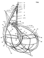
- Figure 2 shows how the fully deployed rescue device for Circulatory recovery accident in heavy is arranged accessible layers, wherein the upper flange. 1 shorter than the lower chord 2, causing the ribcage of the Casualty is raised as far as the abdomen, that's technically, medically and psychologically most favorable posture is formed.
- the difference in the belt length between upper flange 1 and lower flange 2 is through the manual opening of the fuse 25 by the handle 24th and manual or automatic-pneumatic triggering the connecting tube 17 from the stapling system 18th achieved by the action of the Body weight on the bottom loop 2 the bottom strap carrying strap extension 7 triggered while the carrying strap 4 is extended by about 16 cm - 26 cm, with the end of the Connecting hose 17, which forms the fuse 8, from lifted out of the bracket system 9 and so the sub-loop 2 is completely released from the top loop 1.
- the top loop 1 is sufficiently tight around the thorax (Chest) of the casualty is placed and closed, so that Slipping out - as with the usual mountains with drooping poor - is excluded. Because the Thorax of the casualty is opposite the abdomen through the triggered lower loops carrying strap extension 7 easily lifted, wherein the sub-loop 2 of the suspension point 45 of the lock carabiner 15 off in an advantageous Angle of about 120 ° or other branched off and under the Thighs of the casualty is positioned.
- the lower flange 2 is by actuation of the handle 24th for releasing the fuse 25 and the associated Triggering the compressed air cartridge (s) 30 as well as tight Inflating the two inflatable beads 28 from the upper chord 1 splayed and in a Stanfordsitzposition forming
- Position held by the lower belt 2 is not attached to the upper belt 1 pushed and not further pushed away from this is, wherein the safety net 27 between the top chord 1, bottom chord 2 and the two beads 28 is stretched and thus a Sagging of the casualty between the upper and Bottom strap is excluded.
- the casualty is by the Storage in reclining position with retractable net 27 completely secured. His buttocks are opposite to those in the Untergurt 2 held thighs advantageously a little deeper stored, bringing a slide out to the lower flange 2 and the Upper chord 1 is prevented.
- the two handles 21 on the safety net pocket cover 19, which is attached to the top flange 1 on the fabric jacket 5, and the two handles 22 on the lower flange 2 are actuated and when pulled apart by adverse circumstances automatic inflation of the two inflatable beads 28, which are stored protected in the two fabric sheaths 29, prevented or not advantageous.
- the handles 21,22 are together with the handle 23 on the upper flange 1 also operated when the casualty with the rescue device wiped and into the helicopter or otherwise and pulled and when in the rescue device secured casualties in this to another place will be carried.
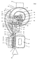
- Figure 3 shows a cross section through the arrangement of Components of each other to a simple mountain sling 1.2 connected upper chord 1 and lower chord 2. Die Connection is through the connecting tube 17, through the fabric sheath 6 is attached to the lower flange 2 and the Clamping system 18, which by the U-profile holder 39 with the Tragegurt 3 of the upper flange 1 is connected, made.
- the upper flange 1 is formed from the double-laid carrying strap 3, on which the U-profile holder 39 is located and which is connected to a counter-plate 40 and the connecting screws 41 fixed to the carrying belt 3.
- the clamp system 18 is screwed to the connecting screw 43.
- a copper cable 42 is guided and fixed for the derivation / grounding of electrical currents.
- the safety net pocket cover 19 is closed with the closure of the safety net pocket cover 20, which is made of a Velcro fastener 47 or other, on the tightly stretched fabric sheath 6 of the lower loop 2, whereby the two inflatable beads 28 together with the fabric sheaths 29 and the safety net 27 are protected in an orderly position.
- the lower flange 2 is made of the double-laid strap 4 educated. This is covered with the fabric sheath 6. Of the Connecting tube 17 is through the fabric sheath 6 with the carrying strap 4 and connected by the handle 22, the the tissue jacket 6 is fixed, for manual triggering the lower belt 2 is actuated from the clamp system 18. For the manual release of the sub-loop 2 is the handle 21, on the closure of the safety net pocket cover 20 is arranged, in the opposite direction to the pulling direction of Handle 22 made. This is the closure of the Fang net pocket 20 opened and the two inflatable beads are in addition to safety net for clamping Approved. In this case, the carrying strap 4 with the foam insert 38 padded, so that the blood circulation in the Thighs of the casualty is not obstructed, with the Foam insert 38 through the fabric sheath 6 in his advantageous position is held on the strap 4.
- the invention achieves a horizontal reclining position for the person to be rescued during recovery.
- the person to be rescued is lifted out of the water with this rescue device in the most beautiful way and rescued.
- This rescue device In this reclining position, health damage during salvage is almost impossible. In this position, injured persons can be recovered without damage. This is certainly not the case with rescue devices of the prior art.
- This rescue device can also be used in rough seas and thus additionally gains its special significance.
Landscapes
- Health & Medical Sciences (AREA)
- General Health & Medical Sciences (AREA)
- Business, Economics & Management (AREA)
- Emergency Management (AREA)
- Engineering & Computer Science (AREA)
- Mechanical Engineering (AREA)
- Ocean & Marine Engineering (AREA)
- Emergency Lowering Means (AREA)
- Distillation Of Fermentation Liquor, Processing Of Alcohols, Vinegar And Beer (AREA)
- Separation Of Suspended Particles By Flocculating Agents (AREA)
- Solid-Sorbent Or Filter-Aiding Compositions (AREA)
Description
- Fig. 1
- das Rettungsgerät in betriebsbereitem Zustand
- Fig. 2
- das Rettungsgerät im Betrieb
- Fig. 3
- einen Querschnitt durch das Rettungsgerät.
Auf dem Tragegurt 3 sind in Längsrichtung die U-Profil-Halter 39 angeordnet, wobei der erste U-Profil-Halter am oberen Ende des Obergurtes 1 mit innen liegenden Klammern oder anderem versehen ist, die das Klammersystem 9 der Sicherung 8 bilden. Der letzte U-Profil-Halter am unteren Ende des Obergurtes 1 ist ebenfalls mit innen liegenden Klammern oder anderem versehen, die das Klammersystem 26 der Sicherung 25 bilden, welche aus einem mit Gewebe ummantelten Schlauch oder anderem gebildet ist und die frei beweglich in das Klammersystem 26 eingespannt und ausgelöst ist.
Dabei ist in den U-Profil-Halter 39 der Schaumstoffkeil 37 eingefügt, wodurch der U-Profil-Halter 39 nebst Tragegurt 3 durch den Schaumstoffkern 36, den darüber gelegten Schaumstoffmantel 35 und den darüber gezogenen Gewebemantel 5, der zwischen der Außenseite des U-Profil-Halters 39 und dem Klammersystem 18 eingespannt und arretiert ist, fest in die Oberschlaufe 1 eingefügt.
An dem Gewebemantel 5 sind der Handgriff 23 und die Fangnetz-Taschendecke 19 befestigt. Zwischen der Fangnetz-Taschendecke 19 und dem Gewebemantel 5, sowie der Schutzlasche 44, die zwischen U-Profil-Halter 39 und Klammersystem 18 eingespannt und befestigt ist, sind die beiden aufblasbaren Wulste 28 nebst Gewebemänteln 29 nicht aufgeblasen zusammen mit dem Fangnetz 27 angeordnet. Dabei ist die Fangnetz-Taschendecke 19 mit dem Verschluß der Fangnetz-Taschendecke 20, der aus einem Klettverschluß 47 oder anderem gebildet ist, an dem stramm gespannten Gewebemantel 6 der Unterschlaufe 2 verschlossen, wodurch die beiden aufblasbaren Wulste 28 nebst den Gewebemänteln 29 und dem Fangnetz 27 in geordneter Position geschützt sind.
In dieser Liegesitzposition sind gesundheitliche Schädigungen bei der Bergung so gut wie ausgeschlossen. In dieser Position können auch verletzte Personen schadenfrei geborgen werden. Das ist bei Rettungseinrichtungen des Standes der Technik durchaus nicht der Fall.
Dieses Rettungsgerät ist auch bei rauer See einsetzbar und gewinnt dadurch zusätzlich seine besondere Bedeutung.
- 1
- Obergurt
- 2
- Untergurt
- 3
- Tragegurt
- 4
- Tragegurt
- 5
- Gewebemantel
- 6
- Gewebemantel
- 7
- Unterschlaufen-Tragegurt-Verlängerung
- 8
- Sicherung
- 9
- Klammersystem
- 10
- D-Bügel
- 11
- D-Bügel
- 12
- Wirbelschäkel
- 13
- Karabiner
- 14
- Bergeseil
- 15
- Verschlußkarabiner
- 16
- D-Bügel
- 17
- Verbindungsschlauch
- 18
- Klammersystem
- 19
- Fangnetz-Taschendecke
- 20
- Verschluß der Fangnetz-Taschendecke
- 21
- Handgriff
- 22
- Handgriff
- 23
- Handgriff
- 24
- Handgriff
- 25
- Sicherung
- 26
- Klammersystem
- 27
- Fangnetz
- 28
- aufblasbarer Wulst
- 29
- Gewebemantel
- 30
- Druckluftpatrone
- 31
- Druckluftzuführung
- 32
- Patronentasche
- 33
- Verbindungsösen
- 34
- Verbindungsösen
- 35
- Schaumstoffmantel
- 36
- Schaumstoffkern
- 37
- Schaumstoffkeil
- 38
- Schaumstoffeinlage
- 39
- U-Profil-Halter
- 40
- Gegenplatte
- 41
- Verbindungsschraube(n)
- 42
- Kupferkabel
- 43
- Verbindungsschraube
- 44
- Schutzlasche
- 45
- Aufhängepunkt
- 46
- Gurt
- 47
- Klettverschluß
Claims (15)
- Rettungsgerät in Form einer Tragvorrichtung für den vertikalen Transport einer verunglückten Person in einer horizontalen Liegesitzposition, bestehend aus zwei jeweils an ihren beiden Enden miteinander verbundenen Gurten (1,2), von denen der eine (1) um den Oberkörper, der andere (2) um die Oberschenkel der verunglückten Person zu legen ist,
und die an ihren Enden mit einem gemeinsamen Koppelglied (12,13) versehen sind, mit dem sie an ein herabgelassenes Ende einer Rettungsleine (14) ankoppelbar sind,
dadurch gekennzeichnet, dass die beiden Gurte (1,2) in der Bereitschaftsstellung eng parallel aneinander anliegen und miteinander einen Strang bildend lösbar miteinander verbunden sind,
dass Mittel vorgesehen sind, mit denen die Verbindung zwischen den beiden Gurten (1,2) zu lösen ist,
und dass das eine Ende (10,11) der beiden Gurte (1,2) an das Koppelglied (12,13) angekoppelt ist, während das andere Gurtende an das erstgenannte Ende (10,11) oder das Koppelglied (12) ankoppelbar ist. - Rettungsgerät nach Anspruch 1,
dadurch gekennzeichnet, dass der Obergurt (1) zwei Wulste (28) trägt, zwischen denen der Untergurt (2) eingelegt ist. - Rettungsgerät nach Anspruch 1,
dadurch gekennzeichnet, dass die Wulste (28) pneumatisch aufblasbar sind. - Rettungsgerät nach Anspruch 1,
dadurch gekennzeichnet, dass die Gurte (1,2) durch Haftmittel, wie Klettbänder, Klebstoff, Haftfolien oder dergleichen, miteinander verbunden sind. - Rettungsgerät nach Anspruch 1,
dadurch gekennzeichnet, dass der Obergurt (1) Klammern trägt, in die der Untergurt (2) eingelegt ist. - Rettungsgerät nach Anspruch 1,
dadurch gekennzeichnet, dass das freie Ende der Gurtkombination (1,2) einen Haken (15) trägt, der in eine von mehreren Ösen (16) am anderen Ende der Gurtkombination einhängbar ist. - Rettungsgerät nach Anspruch 1,
dadurch gekennzeichnet, dass der eine Gurt (2) länger als der andere (1) ist
und dass das über die Länge des anderen Gurtes (2) überstehende Stück gefaltet und aneinander haftend zusammengelegt ist. - Rettungsgerät nach Anspruch 1,
dadurch gekennzeichnet, dass zwischen den Gurten (1,2) ein Netz (27) ausgespannt ist, das an den Gurten (1,2) angebracht ist. - Rettungsgerät nach Anspruch 1,
dadurch gekennzeichnet, dass an dem Obergurt (1) textile oder aus Kunststoff, insbesondere einem weichen Kunststoff, gefertigte einseitig mit einem Klettverschluß (47) und einem Handgriff (21) versehene Halter angebracht sind, welche den Untergurt (2) umfassen. - Rettungsgerät nach Anspruch 1,
dadurch gekennzeichnet, dass seitlich am Obergurt (1) angebrachte Wulste (28) mit Klettverschlüssen und Handgriffen versehen sind, wobei der Obergurt (1) und seine Wulste (28) den Untergurt (2) umfassen und ihn einschließen. - Rettungsgerät nach Anspruch 1,
dadurch gekennzeichnet, dass der Obergurt (1) und/oder der Untergurt (2) pneumatisch aufblasbar sind. - Rettungsgerät nach Anspruch 11,
dadurch gekennzeichnet, dass der eine Gurt (1) Träger einer Halterung für eine Druckluftpatrone (30) und ein handbetätigtes Füllventil für den Gurt (1) oder am Gurt (1) befestigte Wulste (28) ist. - Verfahren zur Rettung einer verunglückten Person mit einer Tragvorrichtung für den vertikalen Transport in horizontaler Liegesitzposition, bestehend aus zwei jeweils an ihren beiden Enden miteinander verbundenen Gurten (1,2), von denen der eine (1) um den Oberkörper, der andere (2) um die Oberschenkel der verunglückten Person zu legen ist, und die an ihren Enden mit einem gemeinsamen Koppelglied (12) versehen sind, mit dem sie an ein herabgelassenes Ende einer Rettungsleine (14) mit Hilfe einer aus zwei Gurten (1,2) bestehenden Tragevorrichtung ankoppelbar sind,
von denen der eine Gurt (1) um den Oberkörper, der andere Gurt (2) um die Oberschenkel der verunglückten Person zu legen ist,
dadurch gekennzeichnet, dass man vor Beginn der Rettungsaktion den Untergurt (2) mit dem Obergurt (1) fest, aber lösbar in paralleler Lage zu einer Gurtkombination verbindet,
dass man zu Beginn der Rettungsaktion der verunglückten Person zunächst die gesamte Gurtkombination um den Oberkörper legt und die Enden der Gurte (1,2) miteinander verbindet und an der Rettungsleine (14) befestigt,
dass man anschließend den Untergurt (2) aus dem Obergurt (1) löst und ihn dann unter das Gesäß der zu rettenden Person schiebt. - Verfahren nach Anspruch 13,
dadurch gekennzeichnet, dass man als Obergurt (1) einen durch Druckluft aufweitbaren Schlauch verwendet oder den Obergurt (1) mit einem durch Druckluft aufweitbaren Schlauch versieht, mit dem man den Untergurt (2) aus seiner befestigten Lage am Obergurt herausdrückt. - Verfahren nach Anspruch 13,
dadurch gekennzeichnet, dass man vor Beginn der Rettungsoperation den Untergurt (2) mittels mit Klettband und Handgriffen versehenen Laschen am Obergurt festlegt und nach Anlegen des Obergurtes (1) die Laschen mit ihrer mit Klettband versehenen Seite mittels der Handgriffe vom Obergurt abzieht und dadurch den Untergurt (2) vom Obergurt (1) löst.
Applications Claiming Priority (3)
| Application Number | Priority Date | Filing Date | Title |
|---|---|---|---|
| DE10037868 | 2000-08-01 | ||
| DE10037868A DE10037868B4 (de) | 2000-08-01 | 2000-08-01 | Verfahren und Gerät zur Rettung von verunglückten Personen |
| PCT/DE2001/002562 WO2002009817A1 (de) | 2000-08-01 | 2001-07-06 | Verfahren und gerät zur rettung von verunglückten personen |
Publications (2)
| Publication Number | Publication Date |
|---|---|
| EP1305084A1 EP1305084A1 (de) | 2003-05-02 |
| EP1305084B1 true EP1305084B1 (de) | 2005-09-28 |
Family
ID=7651211
Family Applications (1)
| Application Number | Title | Priority Date | Filing Date |
|---|---|---|---|
| EP01953897A Expired - Lifetime EP1305084B1 (de) | 2000-08-01 | 2001-07-06 | Verfahren und gerät zur rettung von verunglückten personen |
Country Status (8)
| Country | Link |
|---|---|
| US (1) | US20030176122A1 (de) |
| EP (1) | EP1305084B1 (de) |
| KR (1) | KR20030026985A (de) |
| CN (1) | CN1466477A (de) |
| AT (1) | ATE305327T1 (de) |
| AU (1) | AU2001276317A1 (de) |
| DE (2) | DE10037868B4 (de) |
| WO (1) | WO2002009817A1 (de) |
Families Citing this family (8)
| Publication number | Priority date | Publication date | Assignee | Title |
|---|---|---|---|---|
| DE10313424B4 (de) * | 2003-03-25 | 2006-04-06 | Schwindt, Barbara-Margot | Rettungsgerät für eine im Wasser treibende Person |
| DE10313425B4 (de) * | 2003-03-25 | 2006-05-04 | Schwindt, Barbara-Margot | Verfahren zum Einsatz eines Rettungsgerätes von einem Schiff aus für eine im Wasser treibende Person und Rettungsgerät für eine im Wasser treibende Person |
| DE10313423B4 (de) | 2003-03-25 | 2006-03-02 | Schwindt, Barbara-Margot | Hilfsvorrichtung bei der Anbordnahme einer von in einem Rettungsgerät außen an die Bordwand eines Schiffes gezogenen Person |
| EP1462359A1 (de) | 2003-03-25 | 2004-09-29 | Fachhochschule Hildesheim / Holzminden / Göttingen | Rettungsgerät für eine im Wasser treibende Person |
| CN1788811B (zh) * | 2005-12-29 | 2010-10-06 | 方宏 | 模块式多用途救生网 |
| US11179584B2 (en) | 2019-12-17 | 2021-11-23 | Tethrd LLC | Contoured saddle assembly |
| US11850452B2 (en) * | 2019-12-17 | 2023-12-26 | Tethrd LLC | Harness with continuous linemans loop |
| US12011623B1 (en) | 2023-12-07 | 2024-06-18 | Tethrd Inc | Safety harness assembly |
Family Cites Families (12)
| Publication number | Priority date | Publication date | Assignee | Title |
|---|---|---|---|---|
| US2700781A (en) * | 1951-03-15 | 1955-02-01 | George H Smith | Air sea rescue equipment |
| FR1038909A (fr) * | 1951-06-21 | 1953-10-02 | Double sangle de sauvetage perfectionnée | |
| DE1966239C3 (de) * | 1969-08-08 | 1974-05-30 | Otto 8112 Bad-Kohlgrub Brda | Sitz gurt. Ausscheidung aus: 1940332 |
| US4599073A (en) * | 1984-07-16 | 1986-07-08 | The Sailing Foundation | Man overboard rescue system |
| US4588045A (en) * | 1984-11-05 | 1986-05-13 | Walker Sr Roy D | Descent control device |
| US5010850A (en) * | 1990-09-12 | 1991-04-30 | Sailer Michael P | Seat and harness device |
| DE9213855U1 (de) * | 1992-10-14 | 1992-12-10 | Schwindt, Michael, Prof., 31137 Hildesheim | Segelyacht mit Rettungstalje |
| US5279386A (en) * | 1993-02-25 | 1994-01-18 | Cearley Richard R | Rescue harness |
| DE19745408B4 (de) | 1997-10-02 | 2005-11-03 | Schwindt, Barbara-Margot | Rettungsgerät zum Bergen einer Person aus dem Wasser |
| US6019651A (en) * | 1998-06-06 | 2000-02-01 | Life Safer, Inc. | Flotation device and method of using same |
| US6050869A (en) * | 1999-06-24 | 2000-04-18 | Kellett; K. Craige | Marine rescue snare |
| US6357551B1 (en) * | 1999-12-29 | 2002-03-19 | Bogardus, Iii Vanness H. | Flexible ladder |
-
2000
- 2000-08-01 DE DE10037868A patent/DE10037868B4/de not_active Expired - Fee Related
-
2001
- 2001-07-06 KR KR10-2003-7000984A patent/KR20030026985A/ko not_active Withdrawn
- 2001-07-06 US US10/333,444 patent/US20030176122A1/en not_active Abandoned
- 2001-07-06 AT AT01953897T patent/ATE305327T1/de not_active IP Right Cessation
- 2001-07-06 DE DE50107575T patent/DE50107575D1/de not_active Expired - Fee Related
- 2001-07-06 WO PCT/DE2001/002562 patent/WO2002009817A1/de not_active Ceased
- 2001-07-06 CN CNA018162118A patent/CN1466477A/zh active Pending
- 2001-07-06 AU AU2001276317A patent/AU2001276317A1/en not_active Abandoned
- 2001-07-06 EP EP01953897A patent/EP1305084B1/de not_active Expired - Lifetime
Also Published As
| Publication number | Publication date |
|---|---|
| DE10037868A1 (de) | 2002-02-14 |
| ATE305327T1 (de) | 2005-10-15 |
| EP1305084A1 (de) | 2003-05-02 |
| DE10037868B4 (de) | 2005-12-08 |
| DE50107575D1 (de) | 2005-11-03 |
| US20030176122A1 (en) | 2003-09-18 |
| WO2002009817A1 (de) | 2002-02-07 |
| CN1466477A (zh) | 2004-01-07 |
| KR20030026985A (ko) | 2003-04-03 |
| AU2001276317A1 (en) | 2002-02-13 |
Similar Documents
| Publication | Publication Date | Title |
|---|---|---|
| DE3519866A1 (de) | Mit einem anzug o.dgl. kleidungsstueck einteiliges gurtwerk | |
| EP3755295B1 (de) | Rettungstrage mit integriertem gurt | |
| DE20219484U1 (de) | Vorrichtung zum langsamen und sicheren Sinken von einem Hochhaus | |
| EP3217935B1 (de) | Rettungstrage | |
| DE10037868B4 (de) | Verfahren und Gerät zur Rettung von verunglückten Personen | |
| DE4326657C2 (de) | Rettungshebevorrichtung für eine Segelyacht zum Heben einer Person aus dem Wasser | |
| AT512458B1 (de) | Rettungsgürtel mit aufblasbaren schwimmkörpern | |
| DE10343072B4 (de) | Auffanggurt, insbesondere für Feuerwehrleute | |
| EP2420291A1 (de) | Bauch- oder Beckengürtel und Sitzgurtsystem | |
| DE102019108336B4 (de) | Rettungssystem | |
| EP4260913A1 (de) | Gurtsystem zur absturzsicherung | |
| DE19953689A1 (de) | Weste für Extremsituationen und Rettungszwecke | |
| DE2418374A1 (de) | Rettungstuch fuer verletzte aus hoehen und tiefen in verbindung mit allen krankentragen fuer den waagerechten und senkrechten transport | |
| DE102018205631A1 (de) | Helikoptertaugliche Rettungstrage | |
| DE2304582A1 (de) | Am koerper zu tragende einrichtung, insbesondere zur rettung von im wasser treibenden personen | |
| DE202023103052U1 (de) | Tragegurt-System | |
| WO2018178195A1 (de) | Vorrichtung zum transport einer verletzten, insbesondere nicht gehfähigen person | |
| DE10313424B4 (de) | Rettungsgerät für eine im Wasser treibende Person | |
| DE3000728A1 (de) | Notrutschsystem zur verwendung auf see | |
| DE102018104130B4 (de) | Transportmittel zur Rettung von Personen | |
| DE202016000033U1 (de) | Personentransportvorrichtung | |
| DE202026101613U1 (de) | Schutzbekleidung mit Sicherungsgurt | |
| AT7287U2 (de) | Kombination bestehend aus einer jacke und einem darin integrierbaren sicherheitsgurt | |
| WO2025172018A1 (de) | Haltesystem, anordnung | |
| DE10313425B4 (de) | Verfahren zum Einsatz eines Rettungsgerätes von einem Schiff aus für eine im Wasser treibende Person und Rettungsgerät für eine im Wasser treibende Person |
Legal Events
| Date | Code | Title | Description |
|---|---|---|---|
| PUAI | Public reference made under article 153(3) epc to a published international application that has entered the european phase |
Free format text: ORIGINAL CODE: 0009012 |
|
| 17P | Request for examination filed |
Effective date: 20030215 |
|
| AK | Designated contracting states |
Designated state(s): AT BE CH CY DE DK ES FI FR GB GR IE IT LI LU MC NL PT SE TR |
|
| 17Q | First examination report despatched |
Effective date: 20031021 |
|
| GRAP | Despatch of communication of intention to grant a patent |
Free format text: ORIGINAL CODE: EPIDOSNIGR1 |
|
| GRAS | Grant fee paid |
Free format text: ORIGINAL CODE: EPIDOSNIGR3 |
|
| RAP1 | Party data changed (applicant data changed or rights of an application transferred) |
Owner name: SCHWINDT, BARBARA-MARGOT |
|
| GRAA | (expected) grant |
Free format text: ORIGINAL CODE: 0009210 |
|
| AK | Designated contracting states |
Kind code of ref document: B1 Designated state(s): AT BE CH CY DE DK ES FI FR GB GR IE IT LI LU MC NL PT SE TR |
|
| PG25 | Lapsed in a contracting state [announced via postgrant information from national office to epo] |
Ref country code: IT Free format text: LAPSE BECAUSE OF FAILURE TO SUBMIT A TRANSLATION OF THE DESCRIPTION OR TO PAY THE FEE WITHIN THE PRESCRIBED TIME-LIMIT;WARNING: LAPSES OF ITALIAN PATENTS WITH EFFECTIVE DATE BEFORE 2007 MAY HAVE OCCURRED AT ANY TIME BEFORE 2007. THE CORRECT EFFECTIVE DATE MAY BE DIFFERENT FROM THE ONE RECORDED. Effective date: 20050928 Ref country code: IE Free format text: LAPSE BECAUSE OF FAILURE TO SUBMIT A TRANSLATION OF THE DESCRIPTION OR TO PAY THE FEE WITHIN THE PRESCRIBED TIME-LIMIT Effective date: 20050928 Ref country code: NL Free format text: LAPSE BECAUSE OF FAILURE TO SUBMIT A TRANSLATION OF THE DESCRIPTION OR TO PAY THE FEE WITHIN THE PRESCRIBED TIME-LIMIT Effective date: 20050928 Ref country code: FI Free format text: LAPSE BECAUSE OF FAILURE TO SUBMIT A TRANSLATION OF THE DESCRIPTION OR TO PAY THE FEE WITHIN THE PRESCRIBED TIME-LIMIT Effective date: 20050928 |
|
| REG | Reference to a national code |
Ref country code: GB Ref legal event code: FG4D Free format text: NOT ENGLISH |
|
| REG | Reference to a national code |
Ref country code: CH Ref legal event code: EP |
|
| REG | Reference to a national code |
Ref country code: IE Ref legal event code: FG4D Free format text: LANGUAGE OF EP DOCUMENT: GERMAN |
|
| REF | Corresponds to: |
Ref document number: 50107575 Country of ref document: DE Date of ref document: 20051103 Kind code of ref document: P |
|
| PG25 | Lapsed in a contracting state [announced via postgrant information from national office to epo] |
Ref country code: GR Free format text: LAPSE BECAUSE OF FAILURE TO SUBMIT A TRANSLATION OF THE DESCRIPTION OR TO PAY THE FEE WITHIN THE PRESCRIBED TIME-LIMIT Effective date: 20051228 Ref country code: SE Free format text: LAPSE BECAUSE OF FAILURE TO SUBMIT A TRANSLATION OF THE DESCRIPTION OR TO PAY THE FEE WITHIN THE PRESCRIBED TIME-LIMIT Effective date: 20051228 Ref country code: DK Free format text: LAPSE BECAUSE OF FAILURE TO SUBMIT A TRANSLATION OF THE DESCRIPTION OR TO PAY THE FEE WITHIN THE PRESCRIBED TIME-LIMIT Effective date: 20051228 |
|
| PG25 | Lapsed in a contracting state [announced via postgrant information from national office to epo] |
Ref country code: ES Free format text: LAPSE BECAUSE OF FAILURE TO SUBMIT A TRANSLATION OF THE DESCRIPTION OR TO PAY THE FEE WITHIN THE PRESCRIBED TIME-LIMIT Effective date: 20060108 |
|
| PG25 | Lapsed in a contracting state [announced via postgrant information from national office to epo] |
Ref country code: PT Free format text: LAPSE BECAUSE OF FAILURE TO SUBMIT A TRANSLATION OF THE DESCRIPTION OR TO PAY THE FEE WITHIN THE PRESCRIBED TIME-LIMIT Effective date: 20060228 |
|
| GBT | Gb: translation of ep patent filed (gb section 77(6)(a)/1977) |
Effective date: 20060206 |
|
| NLV1 | Nl: lapsed or annulled due to failure to fulfill the requirements of art. 29p and 29m of the patents act | ||
| REG | Reference to a national code |
Ref country code: IE Ref legal event code: FD4D |
|
| PGFP | Annual fee paid to national office [announced via postgrant information from national office to epo] |
Ref country code: GB Payment date: 20060703 Year of fee payment: 6 |
|
| PG25 | Lapsed in a contracting state [announced via postgrant information from national office to epo] |
Ref country code: LI Free format text: LAPSE BECAUSE OF NON-PAYMENT OF DUE FEES Effective date: 20060731 Ref country code: BE Free format text: LAPSE BECAUSE OF NON-PAYMENT OF DUE FEES Effective date: 20060731 Ref country code: MC Free format text: LAPSE BECAUSE OF NON-PAYMENT OF DUE FEES Effective date: 20060731 Ref country code: CH Free format text: LAPSE BECAUSE OF NON-PAYMENT OF DUE FEES Effective date: 20060731 |
|
| PLBE | No opposition filed within time limit |
Free format text: ORIGINAL CODE: 0009261 |
|
| STAA | Information on the status of an ep patent application or granted ep patent |
Free format text: STATUS: NO OPPOSITION FILED WITHIN TIME LIMIT |
|
| 26N | No opposition filed |
Effective date: 20060629 |
|
| EN | Fr: translation not filed | ||
| PG25 | Lapsed in a contracting state [announced via postgrant information from national office to epo] |
Ref country code: FR Free format text: LAPSE BECAUSE OF FAILURE TO SUBMIT A TRANSLATION OF THE DESCRIPTION OR TO PAY THE FEE WITHIN THE PRESCRIBED TIME-LIMIT Effective date: 20061124 |
|
| PG25 | Lapsed in a contracting state [announced via postgrant information from national office to epo] |
Ref country code: DE Free format text: LAPSE BECAUSE OF NON-PAYMENT OF DUE FEES Effective date: 20070201 |
|
| REG | Reference to a national code |
Ref country code: CH Ref legal event code: PL |
|
| PG25 | Lapsed in a contracting state [announced via postgrant information from national office to epo] |
Ref country code: AT Free format text: LAPSE BECAUSE OF NON-PAYMENT OF DUE FEES Effective date: 20060706 |
|
| BERE | Be: lapsed |
Owner name: SCHWINDT, BARBARA-MARGOT Effective date: 20060731 |
|
| GBPC | Gb: european patent ceased through non-payment of renewal fee |
Effective date: 20070706 |
|
| PG25 | Lapsed in a contracting state [announced via postgrant information from national office to epo] |
Ref country code: GB Free format text: LAPSE BECAUSE OF NON-PAYMENT OF DUE FEES Effective date: 20070706 |
|
| PG25 | Lapsed in a contracting state [announced via postgrant information from national office to epo] |
Ref country code: LU Free format text: LAPSE BECAUSE OF NON-PAYMENT OF DUE FEES Effective date: 20060706 Ref country code: TR Free format text: LAPSE BECAUSE OF FAILURE TO SUBMIT A TRANSLATION OF THE DESCRIPTION OR TO PAY THE FEE WITHIN THE PRESCRIBED TIME-LIMIT Effective date: 20050928 |
|
| PG25 | Lapsed in a contracting state [announced via postgrant information from national office to epo] |
Ref country code: FR Free format text: LAPSE BECAUSE OF FAILURE TO SUBMIT A TRANSLATION OF THE DESCRIPTION OR TO PAY THE FEE WITHIN THE PRESCRIBED TIME-LIMIT Effective date: 20050928 Ref country code: CY Free format text: LAPSE BECAUSE OF FAILURE TO SUBMIT A TRANSLATION OF THE DESCRIPTION OR TO PAY THE FEE WITHIN THE PRESCRIBED TIME-LIMIT Effective date: 20050928 |