EP1302318B1 - Druckvorrichtung - Google Patents
Druckvorrichtung Download PDFInfo
- Publication number
- EP1302318B1 EP1302318B1 EP02023150A EP02023150A EP1302318B1 EP 1302318 B1 EP1302318 B1 EP 1302318B1 EP 02023150 A EP02023150 A EP 02023150A EP 02023150 A EP02023150 A EP 02023150A EP 1302318 B1 EP1302318 B1 EP 1302318B1
- Authority
- EP
- European Patent Office
- Prior art keywords
- ink
- ink supply
- regions
- amount
- printing apparatus
- Prior art date
- Legal status (The legal status is an assumption and is not a legal conclusion. Google has not performed a legal analysis and makes no representation as to the accuracy of the status listed.)
- Expired - Lifetime
Links
- 238000007639 printing Methods 0.000 title claims description 115
- 230000007246 mechanism Effects 0.000 claims description 50
- 238000012546 transfer Methods 0.000 claims description 14
- 230000008859 change Effects 0.000 claims description 12
- 230000000694 effects Effects 0.000 claims description 8
- 238000012545 processing Methods 0.000 claims description 5
- 230000004044 response Effects 0.000 claims description 5
- 239000000976 ink Substances 0.000 description 124
- XLYOFNOQVPJJNP-UHFFFAOYSA-N water Substances O XLYOFNOQVPJJNP-UHFFFAOYSA-N 0.000 description 27
- 238000000034 method Methods 0.000 description 18
- 239000003086 colorant Substances 0.000 description 16
- 230000008569 process Effects 0.000 description 9
- 238000011161 development Methods 0.000 description 8
- 238000004140 cleaning Methods 0.000 description 7
- 238000007599 discharging Methods 0.000 description 5
- 238000005259 measurement Methods 0.000 description 5
- 239000007787 solid Substances 0.000 description 5
- 230000003287 optical effect Effects 0.000 description 4
- 230000007423 decrease Effects 0.000 description 3
- 230000002093 peripheral effect Effects 0.000 description 3
- 238000010586 diagram Methods 0.000 description 2
- 230000007723 transport mechanism Effects 0.000 description 2
- 241000876443 Varanus salvator Species 0.000 description 1
- 239000011248 coating agent Substances 0.000 description 1
- 238000000576 coating method Methods 0.000 description 1
- 230000003028 elevating effect Effects 0.000 description 1
- 239000004744 fabric Substances 0.000 description 1
- 230000006870 function Effects 0.000 description 1
- 238000003384 imaging method Methods 0.000 description 1
- 238000012905 input function Methods 0.000 description 1
- 239000000463 material Substances 0.000 description 1
- 239000003595 mist Substances 0.000 description 1
- 238000007645 offset printing Methods 0.000 description 1
- 229910052709 silver Inorganic materials 0.000 description 1
- 239000004332 silver Substances 0.000 description 1
- -1 silver halide Chemical class 0.000 description 1
- 230000009466 transformation Effects 0.000 description 1
Images




Classifications
-
- B—PERFORMING OPERATIONS; TRANSPORTING
- B41—PRINTING; LINING MACHINES; TYPEWRITERS; STAMPS
- B41F—PRINTING MACHINES OR PRESSES
- B41F33/00—Indicating, counting, warning, control or safety devices
- B41F33/0036—Devices for scanning or checking the printed matter for quality control
- B41F33/0045—Devices for scanning or checking the printed matter for quality control for automatically regulating the ink supply
-
- B—PERFORMING OPERATIONS; TRANSPORTING
- B41—PRINTING; LINING MACHINES; TYPEWRITERS; STAMPS
- B41P—INDEXING SCHEME RELATING TO PRINTING, LINING MACHINES, TYPEWRITERS, AND TO STAMPS
- B41P2233/00—Arrangements for the operation of printing presses
- B41P2233/50—Marks on printed material
- B41P2233/51—Marks on printed material for colour quality control
Definitions
- the present invention relates to a printing apparatus including an ink supply device such as an ink duct device.
- US-A-5 816 164 discloses a typical offset printing apparatus which includes a plurality of ink duct (or ink fountain) devices having ink keys, and can supply variable amounts of ink to respective segments extending across a predetermined feed direction of a paper sheet to be printed. This controls the amount of ink supply in accordance with the area of an image on a printing plate.
- the conventional printing apparatus as described above has been adapted to measure the printed density and printed color on a printed paper sheet and to compare the measured printed density and the measured printed color with a preset target printed density and a preset target printed color, thereby effecting feedback control of the amount of ink supply.
- the printing apparatus effecting the automatic control so that the measured printed density is approximately equal to the target printed density allows even an inexperienced operator to produce properly printed sheets.
- the present invention is intended for a technique related to a printing apparatus including an ink supply device such as an ink duct device.
- a printing apparatus for applying ink to a printing medium while feeding the printing medium in a predetermined feed direction, thereby to provide a printed sheet, comprises: an ink supply mechanism for individually supplying a desired amount of ink through a plurality of ink transfer mechanisms to a plurality of regions defined on the printing medium to provide the printed sheet, each of the regions extending in the feed direction; a density setting element for setting a target printed density for all of the plurality of regions; an image reader provided in a feed path of the printed sheet for capturing an image on the printed sheet to obtain captured image data; an computation device for processing the captured image data to compute a measured printed density for each of the regions; a controller for controlling the amount of ink supplied from the ink supply mechanism for each of the regions so that the measured printed density is approximately equal to the target printed density; and a changing element for changing control by the controller in response to an instruction from an operator, whereby the controller controls the amount of ink supply to a selected one of the regions, based on the instruction from the operator.
- the changing element includes a change key for changing the amount of ink supply for each of the regions in the designated proportion, whereby the controller changes the amount of ink supply to the selected region in the designated proportion each time the change key is manipulated.
- the changing element includes setting key for determining whether or not to cause the instruction to take effect for the controller.
- Fig. 1A is a schematic view of an example of the printing apparatus 100.
- the printing apparatus 100 comprises, as a printing mechanism: first and second plate cylinders (or ink transfer mechanisms) 1 and 2 for holding printing plates; first and second blanket cylinders 3 and 4 for transfer of an ink image from the respective plate cylinders 1 and 2 thereto; an impression cylinder 5 for holding a paper sheet (or a printing medium) p to be printed to which the ink image is transferred from the blanket cylinders 3 and 4; a paper feed cylinder 6 and a paper discharge cylinder 7 for feeding and discharging the sheet p to and from the impression cylinder 5; dampening water supply mechanisms 8 and ink supply mechanisms 9 for supplying dampening water and ink, respectively, to the printing plates on the first and second plate cylinders 1 and 2; a paper feed section 10 for sequentially feeding unprinted paper sheets p arranged in
- the printing apparatus 100 comprises: a printing plate supply section 12 for supplying unexposed printing plates to the first and second plate cylinders 1 and 2; an image recording section 13 for recording an image on the printing plates held on the plate cylinders 1 and 2; a development section 14 for developing the printing plates with the image recorded thereon; and a printing plate discharge section 15 for discharging used printing plates.
- the printing apparatus 100 further comprises an image reader 16 for capturing an image on the printed sheet p to measure an image density; a cleaning device 17 for cleaning the blanket cylinders 3 and 4; and a controller 18 for controlling the overall printing apparatus 100.
- the parts of the printing apparatus 100 will be described in detail.
- the first plate cylinder 1 is movable by a plate cylinder drive mechanism not shown between a first printing position shown by a solid line in Fig. 1A and an image recording position shown by a dash-double dot line.
- the second plate cylinder 2 is movable by a plate cylinder drive mechanism not shown between a second printing position shown by a solid line in Fig. 1A and the image recording position shown by the dash-double dot line.
- the first and second plate cylinders 1 and 2 are in the first and second printing positions, respectively, when a printing process is performed, and are alternately located in the image recording position when a prepress (or plate making) process is performed on the printing plates held on the plate cylinders 1 and 2.
- Each of the first and second plate cylinders 1 and 2 has a peripheral surface capable of holding thereon two printing plates for two respective colors, and includes a pair of gripping mechanisms for fixing the printing plates, respectively, in circumferentially opposed positions 180 degrees apart from each other on the peripheral surface.
- the first blanket cylinder 3 is adapted to rotate in contact with the first plate cylinder 1 in the first printing position.
- the second blanket cylinder 4 is adapted to rotate in contact with the second plate cylinder 2 in the second printing position.
- the first and second blanket cylinders 3 and 4 are approximately equal in diameter to the first and second plate cylinders 1 and 2, and have a blanket mounted on their peripheral surface for transfer of ink images of two colors from the plate cylinders 1 and 2.
- the impression cylinder 5 has a diameter approximately one-half the diameter of the first and second plate cylinders 1 and 2, and is adapted to rotate in contact with both of the first and second blanket cylinders 3 and 4.
- the impression cylinder 5 includes a gripping mechanism capable of holding the single sheet p having a size corresponding to that of the printing plate.
- the gripping mechanism is opened and closed in predetermined timed relation by an opening/closing mechanism not shown to grip a leading end of the sheet p.
- the paper feed cylinder 6 and the paper discharge cylinder 7 are approximately equal in diameter to the impression cylinder 5, and each includes a gripping mechanism (not shown) similar to that of the impression cylinder 5.
- the gripping mechanism of the paper feed cylinder 6 is positioned to pass the sheet p in synchronism with the gripping mechanism of the impression cylinder 5, and the gripping mechanism of the paper discharge cylinder 7 is positioned to receive the sheet p in synchronism with the gripping mechanism of the impression cylinder 5.
- the first and second plate cylinders 1 and 2 in the first and second printing positions, the first and second blanket cylinders 3 and 4, the impression cylinder 5, the paper feed cylinder 6 and the paper discharge cylinder 7 are driven by a printing driving motor not shown to rotate in synchronism with each other.
- the impression cylinder 5 rotates two turns each time the plate cylinders 1 and 2 and the blanket cylinders 3 and 4 rotate one turn.
- two turns of the impression cylinder 5 with the sheet p held thereon effect multicolor printing using two colors from the first plate cylinder 1 and two colors from the second plate cylinder 2 or a total of four colors.
- Two dampening water supply mechanisms 8 are provided for each of the plate cylinders 1 and 2 in the first and second printing positions, and are capable of selectively supplying the dampening water to the two printing plates on each of the plate cylinders 1 and 2.
- Each of the dampening water supply mechanisms 8 includes a water fountain for storing the dampening water, and a set of dampening water rollers for drawing up the dampening water from the water fountain to pass the dampening water to a printing plate surface. At least some of the set of dampening water rollers which contact the printing plate surface are brought into and out of contact with a plate cylinder surface by a cam mechanism.
- the dampening water supply mechanisms 8 need not be provided if the printing plates are of the type which requires no dampening water.
- each of the ink supply mechanisms 9 includes an ink duct or ink fountain 9a capable of adjusting the amount of ink supply for each strip region extending in a predetermined feed direction (or forward direction) of the paper sheet p, and supplies the ink from the ink ducts through a plurality of ink rollers onto the printing plate surface on each of the plate cylinders 1 and 2.
- the ink duct 9a is provided with a plurality of ink keys IK1, IK2, ... IKn. Respective amounts of ink supplied to a linear array of segments defined across the feed direction on the print paper p are independently adjusted by respective ink keys IK1, IK2, ... IKn, whereby the ink density on respective strip regions on the print paper p are controlled. Only the part including the plate cylinder 1 and the blanket cylinder 2 is illustrated in Fig. 1B , and that including the plate cylinder 3 and the blanket cylinder 4 in Fig. 1A has a similar configuration.
- the inks in the ink supply mechanisms 9 are, for example, such that the ink supply mechanisms 9 for K (black) and M (magenta) colors are provided for the first plate cylinder 1, and the ink supply mechanisms 9 for C (cyan) and Y (yellow) colors are provided for the second plate cylinder 2. At least some of the dampening water supply mechanisms 8 and ink supply mechanisms 9 which lie on the paths of movement of the first and second plate cylinders 1 and 2 are adapted to be shunted out of the paths of movement as the first and second plate cylinders 1 and 2 move.
- the paper feed section 10 feeds paper sheets p, one at a time, from a stack of unprinted paper sheets p to the paper feed cylinder 6.
- the paper feed section 10 operates so that one paper sheet p is fed each time the paper feed cylinder 6 rotates two turns.
- the paper discharge section 11 receives printed paper sheets p from the paper discharge cylinder 7 to form a stack.
- the paper discharge section 11 includes a known chain transport mechanism for discharging and carrying a printed paper sheet p, with the leading end of the printed paper sheet p gripped by a gripper (or gripper finger) carried around by a chain.
- the image reader 16 is provided at some midpoint in the path of movement of the printed sheets p discharged by the paper discharge section 11.
- the prepress mechanism of the printing apparatus 100 will be described.
- the first and second plate cylinders 1 and 2 are alternately moved to the image recording position during the execution of the prepress process.
- a friction roller not shown is driven to rotate in contact with the plate cylinder 1 or 2.
- the printing plate supply section 12 includes a cassette roll for storing a roll of unexposed printing plate while shielding the roll of unexposed printing plate from light, a transport roller and a transport guide for transporting the printing plate unwound from the cassette roll to the plate cylinder 1 or 2, and a cutting mechanism for cutting the printing plate into sheet form.
- a silver halide sensitive material is used for the printing plate, and laser light is used to record an image on the printing plate.
- the procedure of a printing plate supply operation includes: causing one of the gripping mechanisms not shown of the plate cylinder 1 or 2 to grip the leading end of the printing plate unwound from the cassette roll; rotating the plate cylinder 1 or 2 in this condition to wind the printing plate around the plate cylinder 1 or 2; then cutting the printing plate to length; and causing the other gripping mechanism to grip the trailing end of the printing plate.
- the image recording section 13 turns on/off laser light to expose a printing plate to the light, thereby recording an image on the printing plate.
- the controller 18 determines the position of the image on the printing plate, and sends corresponding image data to the image recording section 13.
- the image recording section 13 effects main scanning with the laser light emitted from a laser source in the axial direction of the plate cylinder 1 or 2 by using a polarizer such as a polygon mirror, while effecting sub-scanning over the printing plate surface by rotating the plate cylinder 1 or 2.
- the method of scanning may be of the type such that a plurality of laser sources are arranged in the axial direction of a plate cylinder and main scanning is carried out with a plurality of laser beams emitted from the respective laser sources as the plate cylinder rotates.
- the printing plate and the image recording section 13 are not limited to those of the type such that an image is recorded by exposure to light, but may be of the type such that an image is thermally or otherwise recorded.
- the development section 14 develops the printing plate exposed by the image recording section 13.
- the development section 14 draws up a processing solution stored in a processing bath by using a coating roller to apply the processing solution to the printing plate, thereby developing the printing plate.
- the development section 14 includes an elevating mechanism for moving between a position in which the development section 14 is shunted from the plate cylinder 1 or 2 and a position in which the development section 14 is closer to the plate cylinder 1 or 2.
- the development section 14 itself need not be provided if an image recording method which requires no development is employed.
- the first and second plate cylinders 1 and 2 are moved to the image recording position, in which the prepress process is performed by supplying the printing plate and then recording and developing an image. After the prepress process is completed, the first and second plate cylinders 1 and 2 are moved to the first and second printing positions, respectively, for the printing process.
- the printing apparatus 100 is capable of automatically discharging the printing plate after the printing process is completed.
- the printing plate discharge section 15 includes a peeling section for peeling the printing plate from the first or second plate cylinder 1 or 2 in the image recording position, a transport mechanism for transporting the peeled printing plate, and a discharge cassette for discharging the used printing plate so transported.
- the details of the image reader 16 will be described with reference to the schematic view of Fig. 2 .
- the image reader 16 reads an image on the printed paper sheet p gripped and transported by a gripper (or gripper finger) 21 carried around by a chain 20 of the paper discharge section 11.
- the image reader 16 includes an illuminating light source 22 for illuminating the printed paper sheet p, and a reader body 23 for receiving light reflected from the printed paper sheet p to convert the reflected light into an image signal.
- the illuminating light source 22 includes a plurality of line light sources, e.g. fluorescent lamps, arranged in the feed direction of the printed paper sheet p.
- the reader body 23 includes a cover 25 formed with a permeable portion 24 for allowing the reflected light to pass therethrough, a reflecting mirror 26 provided in the cover 25, an optical system 27, and a photodetector 28.
- the cover 25 blocks out disturbance light, dirt, ink mist and the like.
- the permeable portion 24 may be closed by using a light-permeable member or the like, or may be open. If the permeable portion 24 is open, it is preferable that a clean air from outside the printing apparatus 100 is introduced into the interior of the cover 25 to prevent dirt from entering the interior of the cover 25 through the permeable portion 24.
- the reflecting mirror 26 directs incident light from the printed paper sheet p toward the photodetector 28.
- the optical system 27 includes an optical member such as a lens for image-forming the incident light on the photodetector 28.
- the photodetector 28 includes a CCD line sensor for reading the printed image, line by line extending in a direction crosswise to the feed direction of the sheet p.
- This preferred embodiment employs a three-line CCD capable of reading three wavelengths for R, G and B.
- the printed paper sheet p transported by the gripper 21 is vacuum-held and transported by a vacuum suction roller 29. This suppresses fluttering of the sheet p during image reading to stabilize the sheet p.
- the printed paper sheet p has a predetermined color chart previously formed thereon by the image recording section 13 for each of the regions (ink key regions z) corresponding to respective ink keys.
- 100% dense solid patches b for respective CMYK colors are formed in an image end portion (typically, on the trailing end of the printed paper sheet p) in each of the ink key regions z.
- the image reader 16 is capable of imaging the solid patches b to measure the printed densities in the respective ink key regions z.
- the printed density as used herein refers to an optical reflectance density, for each of the RGB colors, which is measured by the use of a predetermined filter.
- a target printed density to provide a standard printed color on a printed sheet is specified based on the reflectance density of the 100% dense solid patch of each ink.
- the standard value thereof in Japan is specified as Japan color.
- Other examples of the color charts includes other-than-100% dense halftone dot patches, line patches, and mixed color patches such as gray patches, which may be prepared and used to measure the printed densities and colorimetric densities. If the color charts and the like are not provided, the image reader 16, of course, may capture the printed image itself and measure the printed density and printed color of a predetermined region.
- the ink key regions z are arranged in a direction crosswise to (preferably, orthogonal to) the feed direction of the sheet p.
- the cleaning device 17 comes in contact with the blanket cylinders 3 and 4 to clean the cylinder surfaces.
- individual cleaning devices are provided respectively for the blanket cylinders 3 and 4.
- the cleaning device 17 includes a cleaning solution supply mechanism, and a wiping mechanism using a cleaning cloth (or wiper).
- the controller 18 is a microcomputer system including various input/output sections and storage sections, and is contained in the printing apparatus 100.
- the controller 18 controls the overall printing apparatus 100 based on a predetermined program operation, and also controls the image reader 16 and the ink supply mechanisms 9.
- the controller 18 controls the image reader 16 to intermittently read an image on a printed paper sheet (sample sheet) p once for every preset number of printed paper sheets, and also controls the ink supply mechanisms 9 (more specifically, the ink key opening of the ink duct) based on the measured printed density by a technique to be described layer.
- the controller 18 controls the image reader 16 to periodically read an image once for every five sheets p. This frequency is substantially unattainable without direct provision of a measuring device (corresponding to the image reader 16 and the controller 18) in the printing apparatus 100.
- the control of the ink supply mechanisms 9 by the controller 18 is so-called feedback control which is specifically effected so that the printed density measured with predetermined frequency is made approximately equal to a preset target printed density.
- the controller 18 also functions as a computation device for performing a computing process upon captured image data read by the image reader 16. For example, the controller 18 perform computation based on the captured image data obtained by the image reader 16, to determine desired measurement data. In this preferred embodiment, the controller 18 converts captured RGB image data obtained by the image reader 16 into image data (measurement data) representing YMCK densities, based on a known transformation. This provides the printed density for each YMCK color of the solid patch provided in each ink key region z.
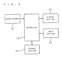
- Fig. 3 is a block diagram according to the present invention.
- the controller 18 is connected to the image reader 16, a storage section 30, a display section 31, and an input section 32.
- the controller 18 controls the image reader 16 to capture an image once for every preset number of printed paper sheets, and determines the measurement data including the printed density and the like from the captured image data.
- the measurement data thus obtained are stored in the storage section 30 including a hard disc, a memory and the like, and are read and used as required by the controller 18.
- the display section 31 specifically corresponds to a CRT monitor, an LCD monitor or the like, and is capable of displaying the measurement data and the like.
- the input section 32 includes a keyboard, a mouse and the like. An operator can use the input section 32 to enter various conditions and to set instructions to the controller 18.
- an LCD monitor having a touch panel input function is used as the display section 31 and the input section 32, and functional portions thereof are integrated together.
- Figs. 4 and 5 show examples of a screen displayed by the display section 31.
- a manual control procedure according to the preferred embodiment will be described with reference to the screen displays shown in Figs. 4 and 5 .
- the manual control procedure refers to a procedure for manually changing the amount of ink supplied from the ink supply mechanisms 9 for each ink key region z.
- Fig. 4 shows a display screen of the display section 31 showing the dampening water and ink being controlled during the printing operation.
- water status indications 40 indicating the amount of dampening water being controlled by the dampening water supply mechanisms 8 appear on the left end of the screen.
- the water status indications 40 are provided respectively for CMYK colors.
- Each of the water status indications 40 contains a water monitor indication 41 providing a 5-step indication of the proper amount of dampening water, and a key 42 for manual up and down adjustment of the amount of dampening water supply. The details of the control of the amount of dampening water is not described herein.
- ink key opening indications 43 for each of the ink key regions z which indicate the amount of ink supply appear for respective CMYK colors in the order named.
- the indications 43 have numerical and bar graph indications of the current amount of ink supply for each of the ink key regions z so that an operator can recognize the settings thereof.
- twelve ink key regions z i.e., twelve ink keys
- the number of ink key regions z is not limited thereto.
- measured printed density indications 44 for each ink key region z appear for respective CMYK colors in the order named.
- Memory indications 45 appear to the left of the measured printed density indications 44.
- the memory indications 45 indicate the numerical range (the upper limit value, the median value and the lower limit value) of the bars presented by the measured printed density indications 44.
- the median value in the memory indications 45 is a preset target printed density. This target printed density is previously inputted and set from the input section 32, and is stored in the storage section 30. The amount of ink supply is controlled so that the measured printed densities are approximately equal to the stored target printed density.
- the controller 18 in this preferred embodiment computes the required amount of ink supply from the difference between the measured printed density and the target printed density to control the ink supply mechanisms 9 so that the amount of ink supply becomes equal to the computed amount.
- other control methods may be used, for example, which include controlling the ink key opening to increase in predetermined increments if the density is low.
- the target printed density is changeable during the printing operation, and the control based on the target printed density is effected substantially in real time as soon as the change is made.
- the target printed densities in a top to bottom sequence are as follows: 1.50 for C color, 1.40 for M color, 1.30 for Y color, and 1.80 for K color.
- Each of the printed density indications 44 appear in the form of a bar in a ⁇ 0.5 range around the target printed density.
- the bar presenting the measured current printed density indicates a higher density if it is above the centerline indicating the target printed density, and indicates a lower density if it is below the centerline.
- the color of the bar is changeable from green (indicating the small difference) to red (indicating the large difference) for increased visibility.
- the key 46 is a manual control key for manual setting of the dampening water and the ink.
- the key 47 is a key for automatic control of only the ink.
- the key 48 is a key for automatic control of both the dampening water and the ink. In general, the key 48 is used to effect the automatic control of both the ink and the dampening water. If the tone of part of an image is desired to be changed as described above, the key 46 is used to make the manual setting of the amount of ink supply.
- a setting transfer key 49 for transfer of settings made by the manual control appears in the middle of the bottom portion of the screen. Other keys are not described.
- the manual control according to the present invention will be described.
- the screen of the display section 31 is changed to a manual control screen shown in Fig. 5 .
- measured printed density indications 50 for each ink key region z appear for respective CMYK colors in the order named.
- the measured printed density indications 50 are substantially similar to the indications 44 shown in Fig. 4 , but have a display range (or a display area in the display section 31) expanded upwardly and downwardly so that an operator easily grasp the status.
- An indication 51 for manual adjustment of the amount of ink supply appears in the bottom portion of the screen.
- the indication 51 contains a color selection key 52 for selection of a color to be manually adjusted among the CMYK colors, a proportion indication 53 for indicating the proportion (%) in which the amount of ink supply is adjusted, a proportion adjustment key 54 for adjusting up and down the proportion, and a selected range adjustment key 55 for execution of the adjustment of the amount of ink supply in a selected ink key region z.
- Region selection keys 56 for selection of the ink key regions z and including keys Nos. 1 through 12 appear over the indications 50.
- Ink key opening indications 57 indicating the current amount of ink supply for the color selected with a touch of the color selection key 52 appear between the indications 50 and the indication 51.
- an operator initially selects a color desired to be adjusted by touching the color selection key 52, and then sets the proportion for adjustment by touching the proportion adjustment key 54.
- the adjustment proportion is set at 10%.
- the operator selectively touches the region selection keys 56 to select the ink key region z in which the amount of ink supply is desired to be changed.
- two or more ink key regions z may be simultaneously selected, or a select all key 58 may be touched if necessary to select all of the ink key regions z.
- the selected ink key region z is highlighted or otherwise suitably indicated.
- the operator touches the selected range adjustment key 55 to increase or decrease the amount of ink supply in the selected ink key region z.
- the ink key opening is adjusted by the amount corresponding to the proportion.
- the adoption of the adjustment using the proportion is advantageous in substantially the same degree of increase or decrease in tone to be adjusted independently of whether the key opening is large or small.
- the ink key opening thus manually set is displayed at the indications 57, and is stored in the storage section 30 for each color and for each ink key region z.
- the touch of the selected range adjustment key 55 changes the amount of ink supply for all of the selected ink key regions z at a time.
- the printing apparatus 100 is adapted to adjust the ink key opening for each of the ink key regions z in ⁇ 1 steps with a touch of the printed density indications 50 corresponding to each ink key region z. For example, a touch of the upper half of the bar indicating the target printed density in one of the indications 50, as designated by the reference character a, increases the second ink key opening by one, and a touch of the lower half of the bar, as designated by the reference character b, decreases the second ink key opening by one.
- the operator touches a return button in a top left portion of the screen to change the screen of the display section 31 to the screen shown in Fig. 4 .
- the operator gets a touch to the automatic control key 47 or 48 while touching the manual control setting transfer key 49 in the screen shown in Fig. 4
- the measured printed density at the ink key opening manually set on the manual control screen shown in Fig. 5 becomes a new target printed density in the corresponding ink key region z, and the automatic control operation is performed based on the new target printed density.
- the printing apparatus 100 normally performs the printing operation while automatically adjusting the ink key opening so that the measured printed density for each ink key region z is approximately equal to the previously set target printed density. If the manual control setting transfer is performed as described above, the measured printed density actually changed on the printed sheets depending on the manually set ink key opening is determined and defined as a new target printed density for the manually set ink key region z. For the manually set ink key region z, the controller 18 effects automatic control using the new target printed density as a target. This allows the manual setting of a partial change in tone and the like to be reflected in the automatic control of the amount of ink supply.
- the controller 18 may determine the measured printed density of a printed sheet which is a predetermined number of printed sheets later than the instant of manually changing the ink key opening, and define this measured printed density as a new target printed density for the changed ink key opening.
- the printing apparatus 100 judges whether to cause the manual settings to take effect or not, depending on whether the setting transfer key 49 is touched or not, as discussed above. Thus, the printing apparatus 100 effects the normal automatic control without a touch of the setting transfer key 49.
- the use of the setting transfer key 49 is advantageous in easily meeting the requirements, if any, to return to the original automatic setting.
- the target printed density may be made changeable individually for each ink key region z.
Landscapes
- Engineering & Computer Science (AREA)
- Quality & Reliability (AREA)
- Inking, Control Or Cleaning Of Printing Machines (AREA)
Claims (8)
- Ein Druckapparat (100) zum Aufbringen von Farbe auf ein Druckmedium, während das Druckmedium in einer vorgegebenen Transportrichtung geführt wird, wodurch ein Druckblatt (p) geschaffen wird, wobei die Druckvorrichtung (100) aufweist:- einen Farbzufuhrmechanismus (9) zum individuellen Zuführen einer gewünschten Farbmenge über eine Mehrzahl von Farbtransfermechanismen auf eine Mehrzahl von Bereichen, die auf dem Druckmedium definiert sind, zum Schaffen des Druckblattes, wobei sich jeder der Bereiche in die Transportrichtung erstreckt;- ein Dichte-Einstellelement zum Einstellen einer Solldruckdichte für alle aus der Mehrzahl von Bereichen;- einen Bildleser (16), der in einem Zufuhrweg auf dem Druckblatt vorgesehen ist, zum Aufnehmen eines Bildes von dem Druckblatt zum Gewinnen der aufgenommenen Bilddaten;- eine Recheneinheit zum Verarbeiten der aufgenommenen Bilddaten zum Berechnen einer gemessenen Druckdichte für jeden der Bereiche;- einen Controller (18) zum Steuern der Farbmenge, die von dem Farbversorgungsmechanismus für jeden der Bereiche zugeführt worden ist, derart, dass die gemessene Druckdichte annähernd der Solldruckdichte gleich ist; gekennzeichnet durchein Änderungselement (46, 49) zum Ändern der Steuerung von dem Controller in Antwort auf einen Befehl von einem Operator;
wobei der Controller (18) die Menge der Farbzufuhr zu einem bestimmten der Bereiche basierend auf dem Befehl von dem Operator steuert. - Der Druckapparat nach Anspruch 1, dadurch gekennzeichnet, dass das Änderungselement zum Ändern der Steuerung durch den Controller (18) in Antwort auf einen Befehl von einem Operator auf einen Befehl antwortet, der einen ersten Befehl zum Ändern der Menge der Tintenzufuhr zu dem bestimmten Bereich in einem zugewiesenen Verhältnis beinhaltet.
- Die Druckvorrichtung nach Anspruch 2, dadurch gekennzeichnet, dass das Änderungselement eine Änderungstaste (46) zum Ändern der Menge der Farbzufuhr für jeden der Bereiche (z) in dem zugewiesenen Verhältnis aufweist, wobei der Controller die Menge der Farbzufuhr zu den ausgewählten Bereichen (z) in dem zugewiesenen Verhältnis jedes Mal, wenn die Änderungstaste betätigt wird, ändert.
- Der Druckapparat nach Anspruch 1, dadurch gekennzeichnet, dass das Änderungselement eine Einstelltaste (49) aufweist zum Bestimmen, ob der Befehl zum Beeinflussen des Controllers zu verursachen ist oder nicht.
- Der Druckapparat nach Anspruch 1, dadurch gekennzeichnet, dass das Änderungselement zum Ändern der Steuerung durch den Controller (18) in Antwort auf einen Befehl auf einen Befehl antwortet, der einen zweiten Befehl zum Ändern der Solldruckdichte während des Druckens beinhaltet.
- Der Druckapparat nach Anspruch 1, dadurch gekennzeichnet, dass das Änderungselement die Solldruckdichte für jeden der Bereiche ändert, um so die Menge an Farbe, die dem Farbzufuhrmechanismus zugeführt wird, zu ändern.
- Der Druckapparat nach Anspruch 1, dadurch gekennzeichnet, dass- der Controller (18) zum Berechnen der ersten Mengen der Druckzufuhr für die jeweiligen Bereiche vorgesehen ist, derart, dass die gemessene Druckdichte annähernd der Solldruckdichte gleich ist und zum Steuern des Farbzufuhrmechanismus (9) in Übereinstimmung mit den ersten Mengen der Farbzufuhr; und- das Änderungselement zum Ändern einer der ersten Mengen von Farbzufuhr, die dem bestimmten aus den Bereichen entspricht, in Antwort auf einen Befehl von einem Operator ausgebildet ist, um so die zweite Menge der Farbzufuhr zu bewirken; und- ein Speicherelement (30) ist zum Speichern der zweiten Menge der Farbzufuhr vorgesehen,wobei der Controller (18) Farbe zu der einen ausgewählten aus den Bereichen (z) in Übereinstimmung mit der zweiten Menge der Farbzufuhr zuführt und Farbe zu den restlichen der Bereiche (z) in Übereinstimmung mit den ersten Mengen der Farbzufuhr zuführt.
- Der Druckapparat nach Anspruch 7, dadurch gekennzeichnet, dass das Speicherelement (30) eine Solldruckdichte für die zweite Menge der Farbzufuhr als die zweite Menge der Farbzufuhr speichert.
Applications Claiming Priority (2)
| Application Number | Priority Date | Filing Date | Title |
|---|---|---|---|
| JP2001316333 | 2001-10-15 | ||
| JP2001316333 | 2001-10-15 |
Publications (2)
| Publication Number | Publication Date |
|---|---|
| EP1302318A1 EP1302318A1 (de) | 2003-04-16 |
| EP1302318B1 true EP1302318B1 (de) | 2008-02-27 |
Family
ID=19134363
Family Applications (1)
| Application Number | Title | Priority Date | Filing Date |
|---|---|---|---|
| EP02023150A Expired - Lifetime EP1302318B1 (de) | 2001-10-15 | 2002-10-15 | Druckvorrichtung |
Country Status (3)
| Country | Link |
|---|---|
| US (1) | US6792863B2 (de) |
| EP (1) | EP1302318B1 (de) |
| DE (1) | DE60225220T2 (de) |
Families Citing this family (8)
| Publication number | Priority date | Publication date | Assignee | Title |
|---|---|---|---|---|
| JP4276046B2 (ja) * | 2003-10-30 | 2009-06-10 | 株式会社小森コーポレーション | 印刷機のインキ供給量調整方法および装置 |
| JP3976727B2 (ja) * | 2003-12-08 | 2007-09-19 | リョービ株式会社 | 印刷機のインキ練り方法及び印刷機 |
| EP1693200B1 (de) * | 2005-02-16 | 2011-07-13 | Dainippon Screen Mfg., Co., Ltd. | Feuchtmittel Regelskala und Feuchtmittel Steuerverfahren |
| JP4698414B2 (ja) * | 2005-12-27 | 2011-06-08 | 大日本スクリーン製造株式会社 | 現像処理方法および印刷機 |
| JP2007261092A (ja) * | 2006-03-28 | 2007-10-11 | Mitsubishi Heavy Ind Ltd | インキ制御装置並びに印刷機及び印刷方法 |
| US20080127846A1 (en) * | 2006-11-02 | 2008-06-05 | Mitsubishi Heavy Industries, Ltd. | Color management system, ink-control device, printer, and printing method |
| DE102008013744A1 (de) * | 2007-04-02 | 2008-10-09 | Heidelberger Druckmaschinen Ag | Verbessertes Kennlinienlernen in Druckmaschinen |
| US8763528B2 (en) * | 2010-12-09 | 2014-07-01 | Goss International Americas, Inc. | Closed loop color control of selected regions using solid color regions within images |
Family Cites Families (26)
| Publication number | Priority date | Publication date | Assignee | Title |
|---|---|---|---|---|
| DE863002C (de) | 1950-12-20 | 1953-01-15 | Joseph Vollmer | Hintereinandergeschaltete Drehmomentwandler mit Regelung durch den Fahrwiderstand |
| US3567923A (en) * | 1968-04-03 | 1971-03-02 | Hurlectron Inc | System for monitoring and controlling the color density of ink during printing |
| US3835777A (en) * | 1973-01-16 | 1974-09-17 | Harris Intertype Corp | Ink density control system |
| DE3666554D1 (en) | 1985-12-10 | 1989-11-30 | Heidelberger Druckmasch Ag | Process for controlling the application of colours in a printing machine, printing device equipped therewith and measuring device for such a printing device |
| US5182721A (en) | 1985-12-10 | 1993-01-26 | Heidelberger Druckmaschinen Aktiengesellschaft | Process and apparatus for controlling the inking process in a printing machine |
| DE3626423A1 (de) * | 1986-08-05 | 1988-02-11 | Deutsche Forsch Druck Reprod | Verfahren und vorrichtung zur beeinflussung der farblichen erscheinung einer farbflaeche bei einem druckvorgang |
| US5148747A (en) * | 1989-06-19 | 1992-09-22 | Heidelberger Druckmaschinen Ag | Process for setting a production run ink zone profile |
| JPH04221641A (ja) | 1990-12-21 | 1992-08-12 | Komori Corp | 多色印刷機の制御装置 |
| JP2824334B2 (ja) | 1990-12-27 | 1998-11-11 | 三菱重工業株式会社 | 印刷物の色調自動制御装置 |
| US5126754A (en) * | 1991-03-20 | 1992-06-30 | Calcomp Inc. | Ink jet printing density controller with programmable angle of travel look-up tables for a plotter |
| DE4126799A1 (de) | 1991-08-14 | 1993-02-18 | Koenig & Bauer Ag | Vorrichtung zum kontrollieren eines bedruckten bogens in einer bogenrotationsdruckmaschine |
| US5841955A (en) * | 1991-12-02 | 1998-11-24 | Goss Graphic Systems, Inc. | Control system for a printing press |
| DE4321177A1 (de) * | 1993-06-25 | 1995-01-05 | Heidelberger Druckmasch Ag | Vorrichtung zur parallelen Bildinspektion und Farbregelung an einem Druckprodukt |
| DE4321179A1 (de) * | 1993-06-25 | 1995-01-05 | Heidelberger Druckmasch Ag | Verfahren und Einrichtung zur Steuerung oder Regelung von Betriebsvorgängen einer drucktechnischen Maschine |
| US5816164A (en) | 1994-04-20 | 1998-10-06 | Heidelberger Druckmaschinen Ag | Method and apparatus for monitoring image formation on a printing form |
| US6382101B1 (en) * | 1997-03-04 | 2002-05-07 | Heidelberg Harris, Inc. & Heidelberger Druckmaschinen | Remote ink fountain selection method and apparatus |
| JP3215647B2 (ja) | 1997-03-06 | 2001-10-09 | リョービ株式会社 | オフセット印刷装置における湿し水量制御装置およびその方法 |
| US6318260B1 (en) * | 1997-05-05 | 2001-11-20 | Quad/Tech, Inc. | Ink key control in a printing press including lateral ink spread, ink saturation, and back-flow compensation |
| US5967049A (en) * | 1997-05-05 | 1999-10-19 | Quad/Tech, Inc. | Ink key control in a printing press including lateral ink spread, ink saturation, and back-flow compensation |
| DE19720954C2 (de) * | 1997-05-17 | 2001-02-01 | Roland Man Druckmasch | Verfahren zum Einrichten der Farbführung im Fortdruck in einer Rotationsdruckmaschine |
| US6318259B1 (en) * | 1997-09-03 | 2001-11-20 | Graphic Systems, Inc. | Apparatus and method for lithographic printing utilizing a precision emulsion ink feeding mechanism |
| DE29916379U1 (de) * | 1999-09-17 | 1999-12-09 | MAN Roland Druckmaschinen AG, 63075 Offenbach | Vorrichtung zum densitometrischen Ausmessen von Druckprodukten |
| JP3427177B2 (ja) * | 2000-01-14 | 2003-07-14 | 長野日本無線株式会社 | 印刷システム |
| JP3561459B2 (ja) * | 2000-03-01 | 2004-09-02 | リョービ株式会社 | インキ供給制御装置 |
| JP3781941B2 (ja) | 2000-03-13 | 2006-06-07 | 大日本スクリーン製造株式会社 | 印刷装置 |
| US6499402B1 (en) * | 2000-05-17 | 2002-12-31 | Web Printing Controls Co., Inc. | System for dynamically monitoring and controlling a web printing press |
-
2002
- 2002-10-09 US US10/266,703 patent/US6792863B2/en not_active Expired - Fee Related
- 2002-10-15 EP EP02023150A patent/EP1302318B1/de not_active Expired - Lifetime
- 2002-10-15 DE DE60225220T patent/DE60225220T2/de not_active Expired - Fee Related
Also Published As
| Publication number | Publication date |
|---|---|
| US20030070570A1 (en) | 2003-04-17 |
| US6792863B2 (en) | 2004-09-21 |
| DE60225220T2 (de) | 2008-05-29 |
| EP1302318A1 (de) | 2003-04-16 |
| DE60225220D1 (de) | 2008-04-10 |
Similar Documents
| Publication | Publication Date | Title |
|---|---|---|
| US6715945B2 (en) | Printing apparatus for performing quality control of printed paper sheet | |
| US4903068A (en) | Photographic printer | |
| EP1149703B1 (de) | Verfahren und Vorrichtung zum Color-Management, und Bilddatenverarbeitungs-Einrichtung | |
| US5774225A (en) | System and method for color measurement and control on-press during printing | |
| EP1302318B1 (de) | Druckvorrichtung | |
| JP3934473B2 (ja) | パッチ測定装置およびそれを組み込んだ印刷装置 | |
| EP1364787B1 (de) | Druckvorrichtung | |
| JP2001347645A (ja) | 印刷パラメータ決定装置および印刷パラメータ決定方法 | |
| EP1302317B1 (de) | Methode zum Voreinstellen der Farbe | |
| US20050200863A1 (en) | Printing machine with a display device for displaying printing states | |
| JPH04208997A (ja) | 文書処理方法及び装置 | |
| US7312890B2 (en) | Printing apparatus | |
| JP2004202968A (ja) | インキ供給量制御方法およびインキ供給量制御装置 | |
| JP3941932B2 (ja) | パッチ測定装置およびそれを組み込んだ印刷装置 | |
| JP2003341016A (ja) | 検出マーク、見当ずれ量測定装置、印刷装置、見当ずれ量測定方法、印刷方法およびプログラム | |
| JP2003191441A (ja) | 印刷装置 | |
| JP2004351814A (ja) | 色調制御装置および代表点決定方法 | |
| EP1586449A1 (de) | Verfahren zum Steuern des Tonwerts | |
| JP2006192680A (ja) | 印刷物検査装置 | |
| US20070209541A1 (en) | Stability display method and stability display apparatus | |
| JP2921624B2 (ja) | 画像プリンタ | |
| EP1832421B1 (de) | Verfahren zur Steuerung der Farbzufuhr und Gerät zur Bestimmung eines repräsentativen Punktes | |
| JP2002077620A (ja) | 画像記録装置、画像記録方法および画像記録装置の較正システム | |
| JP2898262B2 (ja) | カラー画像処理装置 | |
| JPH0524246A (ja) | 画像記録方法及び画像記録装置 |
Legal Events
| Date | Code | Title | Description |
|---|---|---|---|
| PUAI | Public reference made under article 153(3) epc to a published international application that has entered the european phase |
Free format text: ORIGINAL CODE: 0009012 |
|
| AK | Designated contracting states |
Designated state(s): AT BE BG CH CY CZ DE DK EE ES FI FR GB GR IE IT LI LU MC NL PT SE SK TR |
|
| AX | Request for extension of the european patent |
Extension state: AL LT LV MK RO SI |
|
| 17P | Request for examination filed |
Effective date: 20030725 |
|
| AKX | Designation fees paid |
Designated state(s): DE FR GB |
|
| R17C | First examination report despatched (corrected) |
Effective date: 20060912 |
|
| GRAP | Despatch of communication of intention to grant a patent |
Free format text: ORIGINAL CODE: EPIDOSNIGR1 |
|
| GRAS | Grant fee paid |
Free format text: ORIGINAL CODE: EPIDOSNIGR3 |
|
| GRAA | (expected) grant |
Free format text: ORIGINAL CODE: 0009210 |
|
| AK | Designated contracting states |
Kind code of ref document: B1 Designated state(s): DE FR GB |
|
| REG | Reference to a national code |
Ref country code: GB Ref legal event code: FG4D |
|
| REF | Corresponds to: |
Ref document number: 60225220 Country of ref document: DE Date of ref document: 20080410 Kind code of ref document: P |
|
| ET | Fr: translation filed | ||
| PLBE | No opposition filed within time limit |
Free format text: ORIGINAL CODE: 0009261 |
|
| STAA | Information on the status of an ep patent application or granted ep patent |
Free format text: STATUS: NO OPPOSITION FILED WITHIN TIME LIMIT |
|
| PGFP | Annual fee paid to national office [announced via postgrant information from national office to epo] |
Ref country code: DE Payment date: 20081014 Year of fee payment: 7 |
|
| 26N | No opposition filed |
Effective date: 20081128 |
|
| PGFP | Annual fee paid to national office [announced via postgrant information from national office to epo] |
Ref country code: FR Payment date: 20081014 Year of fee payment: 7 |
|
| PGFP | Annual fee paid to national office [announced via postgrant information from national office to epo] |
Ref country code: GB Payment date: 20081015 Year of fee payment: 7 |
|
| REG | Reference to a national code |
Ref country code: FR Ref legal event code: ST Effective date: 20100630 |
|
| PG25 | Lapsed in a contracting state [announced via postgrant information from national office to epo] |
Ref country code: FR Free format text: LAPSE BECAUSE OF NON-PAYMENT OF DUE FEES Effective date: 20091102 Ref country code: DE Free format text: LAPSE BECAUSE OF NON-PAYMENT OF DUE FEES Effective date: 20100501 |
|
| PG25 | Lapsed in a contracting state [announced via postgrant information from national office to epo] |
Ref country code: GB Free format text: LAPSE BECAUSE OF NON-PAYMENT OF DUE FEES Effective date: 20091015 |