EP1300932B1 - Moteur linéaire, support et systéme d'exposition pourvu de ce moteur linéaire - Google Patents
Moteur linéaire, support et systéme d'exposition pourvu de ce moteur linéaire Download PDFInfo
- Publication number
- EP1300932B1 EP1300932B1 EP02256825.7A EP02256825A EP1300932B1 EP 1300932 B1 EP1300932 B1 EP 1300932B1 EP 02256825 A EP02256825 A EP 02256825A EP 1300932 B1 EP1300932 B1 EP 1300932B1
- Authority
- EP
- European Patent Office
- Prior art keywords
- linear motor
- stator
- motor according
- yoke
- coil
- Prior art date
- Legal status (The legal status is an assumption and is not a legal conclusion. Google has not performed a legal analysis and makes no representation as to the accuracy of the status listed.)
- Expired - Lifetime
Links
Images


Classifications
-
- G—PHYSICS
- G03—PHOTOGRAPHY; CINEMATOGRAPHY; ANALOGOUS TECHNIQUES USING WAVES OTHER THAN OPTICAL WAVES; ELECTROGRAPHY; HOLOGRAPHY
- G03F—PHOTOMECHANICAL PRODUCTION OF TEXTURED OR PATTERNED SURFACES, e.g. FOR PRINTING, FOR PROCESSING OF SEMICONDUCTOR DEVICES; MATERIALS THEREFOR; ORIGINALS THEREFOR; APPARATUS SPECIALLY ADAPTED THEREFOR
- G03F7/00—Photomechanical, e.g. photolithographic, production of textured or patterned surfaces, e.g. printing surfaces; Materials therefor, e.g. comprising photoresists; Apparatus specially adapted therefor
- G03F7/70—Microphotolithographic exposure; Apparatus therefor
- G03F7/70691—Handling of masks or workpieces
- G03F7/70758—Drive means, e.g. actuators, motors for long- or short-stroke modules or fine or coarse driving
-
- H—ELECTRICITY
- H02—GENERATION; CONVERSION OR DISTRIBUTION OF ELECTRIC POWER
- H02K—DYNAMO-ELECTRIC MACHINES
- H02K41/00—Propulsion systems in which a rigid body is moved along a path due to dynamo-electric interaction between the body and a magnetic field travelling along the path
- H02K41/02—Linear motors; Sectional motors
- H02K41/03—Synchronous motors; Motors moving step by step; Reluctance motors
- H02K41/031—Synchronous motors; Motors moving step by step; Reluctance motors of the permanent magnet type
Definitions
- the present invention relates to a linear motor, stage apparatus, and exposure apparatus.
- Document US 6,163,091 discloses a linear motor including two parallel magnet arrays having magnet strips of alternating magnetic polarity positioned along the length of the motor.
- a three-phase commutation coil is attached to a center pole such that individual coils are wrapped around the center pole.
- the center pole runs the length of the motor and the three-phase commutation coil slides on the center pole.
- the center pole is attached to the coils.
- the three-phase commutation coil includes any number of sets of three coils, each coil in the set carrying one of the three phases of current.
- a driver supplies three phases of current to the three-phase commutation coil in response to the position of the three-phase commutation coil relative to the magnet arrays.
- the linear motor comprises a stator core frame having substantially U-shaped cross-section defined by an outer part, an inner part and a bottom part coupling them at one end parts thereof, permanent magnets secured to the opposite faces of the outer and inner parts, and a coil disposed in the inner space of the stator core frame.
- a movable section comprises a tubular bottomed movable holding body which penetrates the shaft part and a movable core fixed to the open end part of the holding body, wherein the movable core is disposed in the gap between the permanent magnets of the stator core frame.
- Document JP 11-069761 discloses another linear motor.
- This linear motor comprises a prism-shaped inner yoke, an outer yoke, a yoke block formed by separating the outer yoke from the inner yoke by a specified void, an entire yoke formed by combining a plurality of the yoke blocks into an equilateral polygon, and a mover formed by placing a pair of flat plate-shaped permanent magnetized in the radial direction, in the void at specified intervals in the axial direction so that the direction of magnetization is alternately reversed.
- a cylindrical one as shown in Figs. 32A and 32B is known.
- Fig. 32A is a sectional view of the linear motor taken along its axial direction
- Fig. 32B is a sectional view of the linear motor taken along a direction perpendicular to its axis.
- an annular multilayered yoke (iron core) 1202 formed by combining arcuated multilayered yoke members 1202a each shown in Fig. 32C is formed outside a cylindrical support rod 1201.
- a plurality of annular partial coils 1203 are arrayed outside the multilayered yoke 1202 along the axis of the cylindrical support rod 1201.
- the cylindrical support rod 1201, annular multilayered yoke 1202, and plurality of annular partial coils 1203 described above form the stator of the linear motor.
- the movable element of the linear motor is formed outside the annular partial coils 1203 of the stator, and is formed of an annular yoke 1205 and a plurality of annular partial magnets 1204.
- the plurality of annular partial magnets 1204 include those magnetized in the radial direction of the annulus and those magnetized in the axial direction. More specifically, the direction of magnetization of each annular partial magnet 1204 is determined such that an alternating field is generated inside a cylinder formed of the plurality of annular partial magnets 1204.
- a so-called Halbach layout generates a field close to a sine-wave field of two periods in the cylinder.
- the annular yoke 1205 is arranged outside the plurality of annular partial magnets 1204, and serves as a so-called back yoke.
- the annular yoke 1205 is formed on the rear side of the annular partial magnets 1204 so as to increase the magnetic flux of the magnets.
- the back yoke can be thin.
- the annular multilayered iron core 1202 of the stator serves to intensify the magnetic field the plurality of annular partial magnets 1204 generated inside the annulus.
- the annular multilayered yoke 1202 since the annular partial magnets 1204 form the Halbach layout, the annular multilayered yoke 1202 must be thicker than the back yoke.
- the annular yoke 1205 as the back yoke can be a plain one as it is integral with the magnets 1204.
- the plurality of annular coils 1203 are formed of a plurality of phases (two phases A and B in this example).
- This linear motor is driven by general sine-wave driving, and is controlled such that the current and magnetic flux intersect each other.
- this arrangement employs a movable magnet, stationary coil method, and requires coil switching in addition to general sine-wave driving. This is to supply power to, of the plurality of partial coils 1203, only those that face the plurality of partial magnets 1204, so heat generation is reduced.
- Fig. 33 shows the switching timing for the phase A. In the state shown in Fig. 33 , when the movable element moves to the right, the phase A becomes OFF, and the phase A' becomes ON. Conversely, when the movable element moves to the left, the phase A' becomes OFF and the phase A becomes ON. Regarding phases that oppose other magnets, the phases A and B are all OFF.
- the conventional cylindrical linear motor described above has the following problems in terms of the manufacture and performance, since the partial magnets 1204, the partial coils 1203, and the multilayered yoke 1202 of the stator are cylindrical.
- the first problem is that the multilayered iron core of the stator is difficult to fabricate, and an eddy current is difficult to prevent.
- the annular multilayered yoke 1202 is formed by combining the arcuated multilayered yoke members 1202a. It is difficult to fabricate such arcuated multilayered yoke members 1202a.
- rectangular parallelepiped multilayered yoke members must be fabricated first, and then must be formed into arcuated shapes by wire cutting or the like. With this method, a large number of processing steps are required. It is thus difficult to fabricate a structure with a length corresponding to the length of the stator in the axial direction with one process. Also, it is difficult to obtain highly precise arcs.
- the multilayered structure of the multilayered yoke 1202 is ideally formed completely radially.
- an eddy current is undesirably generated by some components of the magnetic fluxes. It is still also difficult to fabricate a completely radial multilayered iron core.
- the second problem is that the magnet unit of the movable element is difficult to fabricate and variations in thrust are caused.
- the magnet unit of the movable element is formed by inserting the plurality of annular partial magnets 1204 inside the cylindrical yoke 1205.
- the annular partial magnets 1204 it is difficult to set their tolerances. When the tolerances are decreased, the positional precision may improve.
- the short annular partial magnets 1204 must be inserted in the long cylindrical yoke 1205, scuffing tends to occur, and it is difficult to insert the cylindrical magnets 1204 deep into the annular yoke 1205.
- the annular partial magnets 1204 may be inserted in the cylindrical yoke 1205 easily.
- tilt or eccentricity may occur so the annular partial magnets 1204 cannot be attached with high precision.
- the cylindrical yoke 1205 and each annular partial coil 1203 come into contact with each other through only one point, they are not fixed securely to each other.
- magnets and iron attract each other, and magnets attract and repel each other, making the assembly more difficult.
- variations in thrust are caused, leading to degradation in precision of the linear motor.
- a method of making the constituent members of the cylindrical yoke 1205 and annular partial magnets 1204 into small pieces and assembling them has been studied. With this method, however, a cylindrical surface must still be fixed to another cylindrical surface. The number of components increases to increase the number of processing steps, and to guarantee the assembly precision as a whole becomes more difficult. In this manner, a thorough solution cannot be made.
- the third problem is that it is difficult to draw out a conductor wire from the stator coil, thus decreasing the thrust.
- a conductor wire at the winding start portion is always on the inner side.
- the conductor wire need be drawn out to the outer surface of the annular coil 1203, and need be drawn out along the outer surface of the annular coil 1203 in the axial direction.
- a space such as a groove need be formed in the annular multilayered yoke 1202, and the conductor wire need be extended in the space. In the former case, the lead conductor wire is extended in the gap between the magnets 1204 and coils 1203.
- the magnetic gap between the magnets 1204 and stator multilayered iron yoke 1202 must be increased. This decreases the thrust. In the latter case, machining of the multilayered iron core 1202 becomes more difficult, and the magnetic gap increases partially, leading to a decrease in thrust.
- each coil 1203 The conductor wire at the winding end portion of each coil 1203 is always located on the outer surface of the coil. When this conductor wire is directly extended along the outer surface of the coil 1203, a decrease in thrust is caused to accompany an increase in magnetic gap. If the conductor wire at the winding end portion is guided to the inner side of the coil 1203 first and is then extended on the inner surface of the coil 1203, the same problem as that arising when the conductor wire at the winding start portion is extended on the inner surface of the coil 1203 occurs. That is, the multilayered iron core becomes difficult to machine, and the thrust is decreased by an increase in partial magnetic gap.
- the present invention has been made in view of the above situation, and has as its object to provide a linear motor with a structure that can be fabricated easily, and a stage apparatus and exposure apparatus having this linear motor. Additional objects of the present invention include to reduce an eddy current in the yoke, to reduce variations in thrust, to facilitate drawing of the winding out from the coil, and to suppress a decrease in thrust caused by drawing of the winding. Other practical objects of the present invention will be described in the detailed description of the invention.
- the present invention exhibits its effect in any apparatus that utilizes the above linear motor.
- a stage apparatus is defined in claim 27 and comprises the linear motor described above, and a stage driven by the linear motor.
- An exposure apparatus is defined in claim 32 or 33 and comprises the above stage apparatus as a stage apparatus for aligning a substrate or master.
- a device fabrication method according to a a fourth aspect is defined in claim 34 and 35 and comprises the steps of exposing a wafer with a device pattern using the above exposure apparatus, and developing the exposed wafer.
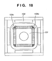
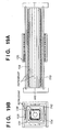
- Figs. 1 to 18 are views showing the structure of a linear motor according to the first embodiment of the present invention.
- Fig. 1 is a sectional view taken along the line of arrows A-A of Fig. 2
- Fig. 2 is a sectional view of the linear motor taken along an axial direction (driving direction)
- Fig. 3 is a view (front view) of the linear motor seen from the axial direction
- Fig. 4 is a view (side view) of the linear motor seen from the side surface.
- One characteristic feature of this embodiment resides in that a structure with a substantially polygonal section (more precisely, a square section) is employed in place of a cylindrical shape, as in the conventional example. More specifically, in the linear motor of this embodiment, magnet arrays 105 of a movable element (movable magnet arrays), back yokes 106 of the movable element, and a coil array 104 of a stator (stator coil array) are formed not in an annular shape but in a substantially polygonal shape (a square shape, to be more precise). This is the characteristic feature of this embodiment.
- the stator is formed of a support member 101, a multilayered yoke (multilayered iron core) 103 serving as a stationary yoke, and the coil array 104. More specifically, the stator has the quadrangular prismatic support member 101 at its most center.
- the support member 101 serves as a base for supporting the quadrangular prismatic multilayered yoke 103 and coil array 104 on its outer surface, and has a flow channel 102 therein through which a refrigerant is to flow.
- the flow channel 102 formed in the support member 101 has, e.g., a circular section, and is connected to a pipe (not shown) to form a refrigerant circulating path.
- This refrigerant is used for cooling the linear motor.
- the support member 101 is preferably made of a material with a good thermal conductivity.
- the cylindrical multilayered yoke is formed by combining the multilayered yoke members such that the surface at the end (end in the direction of arc) of each multilayered yoke member comes into contact with the surface at the end of an adjacent multilayered yoke member. Therefore, the ends of the respective multilayered yoke members must be machined at high precision.
- the four plate-like multilayered yoke members 103a form the multilayered yoke 103 having a square section.
- Each multilayered yoke member 103a has a plate-like (flat) or rectangular parallelepiped shape obtained by stacking a plurality of rectangular (typically, with the same shape) magnetic thin plates having insulated surfaces, as shown in Fig. 5 .
- the multilayered yoke members 103a that form the multilayered yoke 103 can be formed by merely stacking and bonding rectangular thin plates, they can be fabricated very easily.
- the multilayered yoke members 103a are attached to the outer surface of the square support member 101 such that a large number of thin plates which make up the multilayered yoke members 103a are perpendicular to the outer surface of the support member 101 and parallel to the driving axis.
- the respective stacked magnetic thin plates that form each multilayered yoke member 103a are arranged parallel to a surface defined by the position of the central magnetic thin plate and the central axis of the support member 101 or multilayered yoke 103.
- the magnetic fluxes generated by the magnet arrays 105 circulate along the insulating layers of the thin plates, so generation of an eddy current can be minimized.
- the coil array 104 formed of a plurality of partial coils is formed further outside the four plate-like multilayered yoke members 103a, attached to the outer surface of the square support member 101, along the axis.
- the coil array 104 includes four flat portions, and has a substantially quadrilateral shape at its section taken along a direction perpendicular to the axis.
- Each of the winding start portion and winding end portion of the winding of each of the partial coils that form the coil array 104 is arranged near the boundary of a flat portion and another flat portion, i.e., at a corner of the coil array 104 having a substantially quadrilateral shape. This will be described later in detail.
- the movable element is formed by combining four flat units each constituted by the magnet array 105, formed by arraying a plurality of magnets in a planer manner, and the flat back yoke 106 formed on the rear side of the magnet array 105, such that it has a square shape in its section taken along a direction perpendicular to the axis.
- the directions of the poles of the plurality of magnets that form each flat magnet array 105 form a so-called Halbach layout, so that alternating fields are generated on the surfaces of the magnets. It is very easy to fabricate a structure in which the flat magnet array 105 is formed on the flat back yoke 106.
- the magnets must be aligned by inserting an annular member in a closed space, i.e., a cylinder.
- small flat magnets need only be arranged in an array on a large flat surface and be aligned.
- a space around the back yoke 106 can thus be freely used in the fabrication.
- a jig or the like for aligning the magnets at high precision can be utilized easily, so the magnets can be aligned at high precision.
- the magnets can be aligned at high precision in the movable element as a whole. Consequently, variations in thrust caused by aligning errors of the magnets can be reduced.
- a magnetic flux generated in and by each magnet array 105 formed in the movable element includes a component perpendicular to the surface of the magnet array 105 and a component parallel to this surface. These two components circulate through the plate-like multilayered yoke members 103a of the stator.
- the plurality of thin plates that form each multilayered yoke member 103a of the stator are arranged to be perpendicular to the surface (flat portion) of the corresponding magnet array 105.
- the magnetic flux perpendicular to the magnet surface formed by the magnet array 105 and the magnetic flux parallel to the magnet surface both enter the thin plates.
- the loop of the eddy current is limited within the thin surfaces of the thin plates. Therefore, occurrence of the eddy current can be minimized by a very simple arrangement that can be fabricated easily.
- the magnet arrays 105 and back yokes 106 form substantially square shapes obtained by combining float shapes, and the coil arrays 104 form a substantially quadrilateral shape.
- all the problems of the prior art i.e., the arcuated multilayered iron core of the stator is difficult to fabricate, the eddy current is not suppressed sufficiently, the cylindrical yoke and annular magnets of the movable element are difficult to assemble, and the aligning precision of the annular magnets is accordingly degraded to promote variations in thrust, can be solved.
- a winding start portion 104c and winding end portion 104d of the coil are arranged each at the corner (near the boundary of one flat portion 104a and another) of the substantially square coil array 104.
- the winding start portion 104c is always located on the inner surface of the coil array 104, and the winding end portion 104d thereof is always located on the outer surface of the coil array 104.
- the conductor wire may be drawn out from the vicinity of such corner of the coil array 104 along the axis.
- Fig. 17 shows this state.
- the winding start portion 104c and winding end portion 104d of the winding are arranged at the corners of the substantially square coil array 104, and the conductor wires are drawn out from there along the axis.
- the lead conductor wires are drawn out through near the corners of the substantially square coil array 104 in the axial direction to the end of the coil array 104 in the axial direction.
- no magnet arrays 105 or multilayered yoke members 103a multilayered iron core 103 are present at the corners of the substantially square coil array 104.
- the lead conductor wires of the coil array 104 when the lead conductor wires of the coil array 104 are extended through these spaces, they can be drawn out to the end of the coil array 104 in the axial direction without arranging them in the magnetic gap or partial cutting of the multilayered yoke members 103a, i.e., without accompanying any decrease in thrust at all.
- the four flat magnet arrays 105 are arranged to form a substantially square shape.
- the coil array 104 of the stator has a substantially square shape to match the shape formed by the coil array 104.
- the multilayered iron core 103 of the stator has a substantially square shape to match the shape of the coil array 104.
- spaces can be formed at the corners of the coil array 104 without accompanying a decrease in thrust. These spaces can be utilized as spaces where the lead conductor wires of the coil array 104 are to be extended.
- all the windings can be drawn out from the inner surface of the coil array 104.
- the winding end portion located on the outer surface of the coil array 104 must be guided to the inner surface at the corner of the coil array 104.
- the winding start portion at the inner surface of the coil array 104 can be guided to the outer surface thereof, and all the windings can be drawn out from the outer surface thereof. Either method utilizes spaces (inner or outer surface) at the corners of the square coil array 104.
- the first method of solving these issues is a method that uses aligning plates.
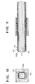
- Figs. 9 to 12 show this method.
- Figs. 9 and 10 show a state after the plurality of coils 104 are assembled by using aligning plates 107.
- Fig. 9 is a sectional view of the linear motor taken along the direction of axis
- Fig. 10 is a sectional view of the linear motor taken along a plane perpendicular to the axis.
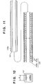
- Figs. 11 and 12 show a method of fabricating the structure shown in Figs. 9 and 10 .
- the structure shown in Figs. 9 and 10 has the aligning plates 107 between the coil arrays 104 and the respective multilayered yoke members 103a.
- Each aligning plate 107 is a plate having a comb tooth-like section with a width w1 almost equal to that of the flat portion of the coil array 104 and extending in the axial direction.
- the partial coils are arranged among the comb teeth of the comb tooth-like shape.
- the aligning plate 107 is arranged between the multilayered yoke member 103a and the coil arrays 104. A total of four aligning plates 107 are used.
- Each aligning plate 107 has comb teeth 107b at high pitch precision.
- the coils 104 are aligned by the pitch precision of the comb teeth 107b. Hence, errors in the widths of the respective partial coils that form the coil array 104 will not accumulate to displace the respective partial coils.
- the aligning plate 107 is made of an insulating material.
- a base 107a of the aligning plate 107 insulates the respective partial coils of the coil array 104 and the plate-like multilayered yoke member 103a from each other, and the comb teeth 107b of the aligning plate 107 insulate the partial coils from each other.
- the aligning plates 107 since the four aligning plates 107 are arranged such that their ends in the widthwise direction are separated from each other, the spaces at the corners of the coil array 104 are left as they are on both the inner and outer surfaces of the coil array 104. Therefore, the aligning plates 107 do not interfere with the drawing-out operation of the windings of the coil array 104 in accordance with the above method.
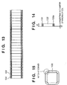
- FIG. 13 to 15 show this method.
- bobbins 108 having high precision in the axial direction are prepared, and conductor wires are wound on them, thus fabricating the respective partial coils.
- the partial coils with bobbins are juxtaposed next to each other to form the coil array 104.
- a rod-like member formed of the support member 101 and multilayered yoke 103 (four plate-like multilayered yoke members 103a) is inserted in the coil array 104, thus assembling the stator.
- the bobbins 108 are also made of an insulating material, and insulate the partial coils from each other, and the partial coils and the plate-like multilayered yoke members 103a from each other. Side plates formed on each bobbin 108 have notches at their corners. Because of this consideration, the conductor wires at the winding start portion and winding end portion of each partial coil of the coil array 104 can be extended near the corners along the axis. A thickness w3 of each side plate formed on the bobbin 108 is larger than 1/2 the diameter of the winding of the coil 104.
- Figs. 7 and 8 show modifications of the support member 101.
- a refrigerant circulating path is formed in the support member 101, and a refrigerant is circulated in it, thereby cooling the linear motor.
- the support member 101 is preferably made of a material with good thermal conduction, e.g., SiC or aluminum. Even when the support member 101 is made of a conductor such as aluminum, the magnetic flux of the magnets circulates in the multilayered yoke members 103a. Hence, the magnetic flux does not leak to the support member 101, and no eddy current is generated.
- the support member 101 is fabricated from SiC, complicated machining is difficult to perform, so a simple flow channel 102 as shown in Fig. 1 is preferably formed in the support member 101.
- the support member 101 When the support member 101 is fabricated from aluminum, it can have a complicated sectional shape by means of, e. g. , extrusion. Hence, a radial flow channel (flow channel having a plurality of grooves arranged radially about an axis as the center) as shown in Fig. 7 , or a honeycombed flow channel as shown in Fig. 8 may be formed, so the heat transfer efficiency between the support member 101 and the refrigerant is improved easily.
- the material of the support member 101 and the shape of the flow channel 102 are not limited, the support member 101 preferably has an outer shape with a flat portion that matches the coil array 104 which is formed to include flat portions.
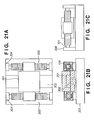
- Figs. 19A, 19B , 20A, and 20B are views showing the second embodiment of the present invention.
- a partition 110 is formed between magnet arrays 105 and a coil array 104.
- a refrigerant is circulated between the partition 110 and coil array 104 as well, so the cooling ability of the coil array 104 is improved.
- the partition 110 may have a square shape, as shown in Figs. 19A and 19B , a cylindrical shape, as shown in Figs. 20A and 20B , or any other shape.
- the partition 110 is made of an insulating material such as a ceramic material or resin.
- Figs. 21A to 21C are views showing a uni-axial stage apparatus according to the third embodiment of the present invention.
- Fig. 21A is a plan view
- Fig. 21B is a sectional view
- Fig. 21C is a side view.
- This uni-axial stage apparatus has a linear motor according to the first embodiment, which has a substantially square coil array 104.
- a so-called T-shaped air slide 302 is fixed on a surface plate 303, and a stage 301 is supported to be slidable in a uni-axial direction along the T-shaped air slide 302.
- Linear motors 300 each having a substantially square coil array 104 according to the first embodiment are arranged on the two sides of the stage 301.
- the movable elements of the linear motors 300 are connected to the stage 301, and the stators thereof are fixed to the surface plate 303 through support columns 304 arranged at the front and rear ends of support members 101.
- a cooling medium circulates in the stators of the linear motors 300 through the support columns 304.
- the stage apparatus of this embodiment is advantageous in that heat generated with the same thrust is smaller than that of a case using a conventional cylindrical linear motor.
- this stage apparatus as the interiors of the stators are cooled, heat generation by coils can be exhausted efficiently.
- This stage apparatus is also advantageous in the following respect. Namely, since the aligning precisions of the magnets and coils of the linear motors 300 are higher than in the conventional cylindrical linear motor, variations in thrust are small, and an error from a target, which occurs particularly when the linear motors are driven at a constant speed, can be decreased.
- Figs. 22B and 22C are views showing a linear motor according to the fourth embodiment of the present invention
- Fig. 22A is a view showing a stage apparatus utilizing this linear motor.
- the number of units of flat magnet arrays 105 that form the movable element is four, and the coil array 104 has a substantially square shape.
- the number of units of flat magnet arrays 405 is three, and each coil 404 has a substantially triangular shape.
- the characteristic feature of this structure resides in that its spaces at the corners of the coil, particularly the spaces on the outer surfaces of the corners of the coil, are larger than in the first embodiment. Therefore, the number of windings that can be drawn out is larger than that of the first embodiment. This increases the number of partial coils that can be arranged, so the stroke can be extended.
- the arrangement of the stage apparatus is the same as that of the third embodiment.
- the movable element has a substantially triangular section, the movable element has a higher rigidity than in the third embodiment, and the minimum-degree eigenfrequency increases.
- Figs. 23B and 23C are views showing a linear motor according to the fifth embodiment of the present invention
- Fig. 23A is a view showing a stage apparatus utilizing this linear motor.
- the number of units of flat magnet arrays 505 that form the movable element is two, and each coil 504 has a substantially elliptic shape. According to this embodiment, the spaces at the corners (ends) of the coil 504 become much larger than in the fourth embodiment, so a larger number of coils 504 than in the fourth embodiment can be arranged.
- the movable element When this linear motor 500 is applied to a stage apparatus, the movable element has a higher rigidity than in the fourth embodiment, and the control performance is further improved.
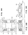
- Figs. 24A to 24C are views showing linear motors according to the sixth embodiment, and a stage apparatus utilizing them.
- Fig. 24A is a plan view
- Fig. 24B is a sectional view
- Fig. 24C is a side view.
- the linear motor stators are fixed to the surface plate 303 through the support columns 304.
- linear motor stators on the right and left sides of a stage 301 are fixed to mass elements 610 through support columns 304.
- the mass elements 610 form an air slide (not shown) with respect to the surface plate 303, and are guided by rollers 611 provided on their side surfaces, so they are supported to be slidable in the uni-axial direction.
- the rollers 611 may be mechanical ones as shown in Figs. 24A and 24C .
- magnetic bearings or linear motors may be used to apply a force to the rollers 611 in a non-contact manner, so lateral movement and rotation of the rollers 611 are regulated.
- Figs. 25A to 25C are views showing linear motors according to the seventh embodiment of the present invention, and a stage apparatus utilizing them.
- Fig. 25A is a plan view
- Fig. 25B is a sectional view
- Fig. 25C is a side view.
- linear motors each with a substantially square section according to the first embodiment are applied to a uni-axial stage, and the stators of the linear motors are integrally coupled to uni-axially movable mass elements, thus realizing a passive counter.
- the arrangement inherent to this embodiment is as follows. Namely, mass elements 710 are arranged to surround the movable element and stator of a corresponding linear motor 700, and are connected to each other by end plates 711 provided at the front and rear ends. Flow channels 720 are formed in the mass elements 710 arranged to surround the movable element and stator. A refrigerant is circulated through the flow channels 720, thereby cooling the mass elements 710.
- the barycenter of the integral body of the stator and mass elements 710 can be set to almost coincide with the line in which the thrust of the corresponding linear motor 700 acts.
- the moment of the integral body to act on a surface plate 303 can be decreased to substantially zero.
- the length of the entire integral body in the axial direction can be decreased to be smaller than that of a case wherein the mass elements 710 are arranged in front of and behind the stator, rather than at the two ends of the stator.
- the mass elements 710 can serve also as heat partitions. This can remove heat generation by the coils, which cannot be completely removed by the refrigerant provided in the stator, can be removed almost completely. Most of the heat generated by the coils is transferred to the refrigerant in the support member 101 by heat conduction through a multilayered iron core 103 (plate-like multilayered yoke member 103a) and the support member 101. Heat is released to the air outside the coils as well. Then, the atmosphere outside the coils fluctuates.
- the measurement precision is degraded.
- the entire stator is surrounded by walls serving as the mass elements 710, and a refrigerant is set to flow in the walls, thereby cooling the interiors of the walls.
- a refrigerant is set to flow in the walls, thereby cooling the interiors of the walls.
- the arrangement of the second embodiment also has a function of recovering heat that cannot be completely removed by the refrigerant in the support member of the stator.
- a partition is formed between the magnets and coils, and the refrigerant is circulated within the partition.
- the partition may be preferably as thin as possible.
- the thickness of the partition cannot be decreased very much. Particularly, when water is used as the refrigerant in place of oil, insulation between the coils and refrigerant must be assured.
- the partition and magnets move relative to each other, if the partition is formed of a conductor, an eddy current is generated to cause further heat generation.
- the material of the partition is limited. It is easy to form a cylindrical partition from a metal but is difficult to form it from a ceramic material or resin.
- the seventh embodiment since nothing is formed between the magnets and coils, heat generation by coils with the same thrust does not increase. Also, insulation between the coils and refrigerant need not be considered. Consequently, safety and reliability of the coils improve.
- the former when the method of forming a heat partition to surround the movable element and stator and supplying a refrigerant in the partition is compared with the method of forming a partition between the movable element and stator coils and supplying a refrigerant between the partition and stator coils, the former has excellent effects in that it can solve all the problems of (1) an increase in magnetic gap due to the partition and a refrigerant space, (2) insulation between the partition and stator coils, and (3) limitation on the material of the partition.
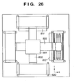
- Figs. 26 , 27A , 27B , 28A, and 28B are views showing the arrangement of a bi-axial stage apparatus according to the eighth embodiment of the present invention.
- a bi-axis stage is formed by using as the base the arrangement of the uni-axial stage apparatus according to the seventh embodiment.
- the linear motor represented by the first embodiment is of a type which uses movable magnets and stator coils, and the space density of the coils is increased.
- the first embodiment is characteristic in that its stator is heavy.
- mass elements are further added to the stator, so the stator is heavier.
- Figs. 28A and 28B The basic arrangement of the stage is as follows. As shown in Figs. 28A and 28B , an X beam 802 and Y beam 805 respectively guided by an X yaw guide 811 and Y yaw guide 812 are formed on a surface plate 810, and a stage 801 which is slidably guided alternately by the X beam 802 and Y beam 805 through an air slide is arranged at the intersection of the X beam 802 and Y beam 805.
- This stage is combined with the linear motor according to the seventh embodiment shown in the seventh embodiment, and a passive counter with a cooling function.
- Fig. 26 is a plan view
- Figs. 27A and 28B are front views.
- a linear motor stator for driving the X beam 802 is supported through a bulking plate to be slidable with respect to the surface plate 810.
- a stator and mass elements themselves arranged to surround it are supported to be slidable with respect to the surface plate 810, in the same manner as in the seventh embodiment.
- both the X and Y driving systems have the same convey mass.
- linear motors having the same specification can be used as the X and Y driving systems.
- a heat source can be arranged away from the stage. Since the stage has a quartered square-type arrangement, a passive counter can be formed two-dimensionally.
- Fig. 29A is a view showing a stage apparatus according to the ninth embodiment of the present invention.
- Figs. 29B and 29C are views showing linear motors mounted on this stage. This embodiment is obtained by improving the seventh embodiment so it is particularly suitable for use in vacuum.
- a connecting portion 902 between a movable element 950 of each linear motor and a stage 901 is formed at the corner of the substantially square movable element 950, and several processes against vacuum are performed. These are the characteristic features of this embodiment.
- the connecting portion 902 between each movable element 950 and the stage 901 is formed at the corner of the movable element 950, in order to further improve the ability of recovering heat that cannot be completely removed by a refrigerant circulating in a support member 961 of a stator 960, as in the seventh embodiment.
- the connecting portion between each movable element and the stator is formed at almost the center of one side of the square movable element.
- the heat partition for surrounding the movable element and stator cannot accordingly be formed at this connecting portion, the heat partition is cut at the center of one side of the substantially square movable element, as shown in Fig. 29B .
- the side (surface) of the movable element is a portion that faces the side (surface) of a coil, and thus heat is transferred to it easily.
- heat generated by the coils can be easily transferred to the sides (surfaces) of the movable element by conduction if the stage apparatus is used in an atmosphere, and by radiation if the stage apparatus is used in vacuum. Namely, heat can be easily transferred when the stage apparatus is used in either environment of atmosphere or vacuum.
- the connecting portion 902 between each movable element 950 and the stage 901 is preferably formed at the corner of the movable element 950.
- the heat partition serving as mass elements as well can face the sides (flat portions) of the coils almost completely, so the heat exhaust performance is improved.
- a thin cover 963 is arranged outside coils 962. This aims at preventing gas release from the coils 962 and a multilayered yoke 964 inside the cover 963.
- the coils 962 and multilayered yoke 964 use a resin that holds their shapes. It is known that if such coils 962 and multilayered yoke 964 are directly brought into vacuum, the vacuum degree is decreased.
- the surface of the movable element 950 is preferably Ni- or chromium-plated, or a reflection member such as an aluminum foil is preferably adhered to it, so the movable element 950 will not absorb heat by radiation easily.
- This reflection process is preferably performed for all portions that face the coils 962. In other words, this reflection process should be performed for all the inner surface of the movable element 950.
- the inner surfaces of mass elements 970 formed to surround the movable element 950 and stator 960 are preferably processed with black anodized aluminum, or absorbing members such as black plates are preferably adhered to them. This helps heat radiated from the coils 962 to be absorbed easily.
- the mass elements 970 are supported on a surface plate 981 with V guides 980.
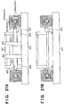
- Fig. 30 is a view showing a stage apparatus according to the tenth embodiment of the present invention.
- the ninth embodiment is improved to increase the rigidity of the attaching portions.
- the heat exhaust ability by the mass elements 970 is considered important, and accordingly the connecting portion 902 between each movable portion 950 and the stage 901 is formed at the corner of the movable element 950.
- the rigidity at the corner generally tends to decrease, so the upper limit of the servo gain obtained when a positional servo is applied to the stage 901 tends to be limited.
- the frame member of the movable element is formed of a high-rigidity material, e.g., a ceramic material, other than a yoke material.
- the back yoke formed on the rear surface of the flat magnet array has both the function of circulating the magnetic flux of the magnet array and the function of forming the structure of the movable element. If the magnet array has a Halbach layout, the back yoke may be thin. However, to maintain the rigidity of the structure, the back yoke must be thick. In view of this, the function of magnetic flux circulation and the function of the structure are separated, and a material with a higher rigidity than that of iron is employed to form the structure, so the rigidity of the movable element with the same thickness can be increased.
- a necessary minimum back yoke 1001 for circulating the magnetic flux is formed on the rear side of a magnet array 1003.
- the magnet array 1003 and the thin back yoke 1001 are supported by a ceramic plate 1002.
- Four sets each having this structure are combined to form a movable element. As a result, the rigidity of the movable element is increased, and accordingly the servo performance of the stage is improved.
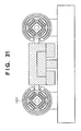
- Fig. 31 is a view showing a stage apparatus according to the eleventh embodiment of the present invention. This embodiment provides a modification of the tenth embodiment.
- the structure is not necessarily formed of flat surfaces.
- One aspect of the present invention is to form the magnet arrays of the movable element and the multilayered iron core of the stator to have substantially rectangular parallelepiped shapes or substantially flat shapes.
- the movable element can have any shape.
- the shape of the structure is influenced by the shape of the magnet array.
- the degree of freedom of the shape of the structure increases.
- an annular ceramic member 1101 can be used as the structure of the movable element, as in this embodiment. According to this embodiment, since the structure of the movable element has an annular shape, the rigidity of the movable element is increased more than in the tenth embodiment.
- Figs. 37 to 43 are views showing the arrangement of a linear motor according to the twelfth embodiment of the present invention.
- Fig. 37 is a sectional view taken along the line of arrows A - A of Fig. 38
- Fig. 38 is a sectional view of the linear motor taken along its driving axis.
- the coil array of the stator (stator coil array) has a plurality of flat portions, and the multilayered yoke of the stator also has a plurality of flat portions.
- a coil array 1304 of the stator has an annular shape, as shown in Fig. 37
- multilayered yoke members 1303a which form a multilayered yoke (stator yoke) 1303 inside the coil array 1304 of the stator have arcuated surfaces, as shown in Figs. 39 and 40 or 41 .
- the movable magnet of the movable element can be formed of a plurality of magnet arrays 1305, so the movable magnet can be assembled easily.
- the magnetic flux of the magnet arrays 1305 circulates along the insulating layer of the multilayered yoke 1303, thereby preventing an eddy current substantially completely.
- the windings of the coil array 1304 can be drawn out along spaces near the boundaries of the plurality of multilayered yoke members 1303a.
- this embodiment is different from the first to eleventh embodiments in the shape of the coil array, the shape of the multilayered yoke, and the shapes of the magnet arrays.
- the coil array 1304 has an annular shape. This is the result of considering easy winding of the coil conductor wires and the productivity.
- the first to eleventh embodiments have the excellent effects as described above. If, however, the multilayered yoke has a substantially square section, the tension acting on the conductor wires when winding the coil conductor wires changes largely. This poses limitation on high-speed winding. Also, the coil tends to bulge at the center of the flat portion of the multilayered yoke, thus narrowing the magnetic gap. Therefore, the gap between the movable magnet and the coils must be large.
- the coil array 1304 has an annular shape, a change in tension which occurs when winding coil conductor wires decreases, so the coil conductor wires can be wound at a very high speed, while the coil shape has excellent uniformity (axial symmetry). Consequently, the magnetic gap need not be formed large in consideration of the coil bulge described above.
- the multilayered yoke 1303 is also formed of the arcuated multilayered yoke members 1303a.
- each multilayered yoke member 1303a is not formed with a fan-like shape, as in the conventional case.
- surface-insulated magnetic thin plates 1330 with the same shape are stacked while slightly being shifted substantially along the surface of a support member 1301, thus assembling each multilayered yoke member 1303a.
- the surfaces of the thin plates 1330 directly form the surfaces at the two ends (two ends in the circumferential direction) of the multilayered yoke member 1303a formed by stacking in an arcuated manner.
- the manufacture is thus much easier than in the conventional case wherein the two ends of the multilayered yoke members are machined in the radial direction about the driving axis as the center.
- smooth arcuated surfaces may be formed by machining such as wire cutting.
- machining may not be performed, but thin plates may be merely arrayed along the cylindrical surface of the cylindrical support rod 1301, and be fixed by adhesion or the like.
- the latter method may be simpler. Since, however, the magnetic thin plates 1330 with the same shape are arrayed along the cylindrical support rod 1301, the outer surface of the arcuated multilayered yoke member 1303a becomes identical to a shape obtained by translating the side surface of the cylindrical rod, which is not concentric with the cylindrical rod. Accordingly, a small gap is formed between the coil array 1304 and the annular coils 1303. Yet, this poses a problem only when the cylindrical rod has a small diameter, and can be solved in a design manner to a certain degree.
- each magnet array 1305 which corresponds to the coil array 1304 forms a concave arcuated surface. That surface of the magnet array 1305 which is on the side of back yoke 1306 is flat, in the same manner as in the first to eleventh embodiments.
- the direction of magnetization of the magnet array 1305 is not perpendicular to the cylindrical surface (i.e., the radial direction) throughout the entire width of the respective magnet array 1305, but is perpendicular to the flat surface on the rear surface of the magnet array 1305.
- the magnetic field formed by the magnet array 1305 becomes perpendicular to the lower surface of the magnet array 1305, so the magnetic flux circulates along the insulating layers of the respective magnetic thin plates 1330 which form the arcuated multilayered yoke member 1303a. Therefore, the eddy current can be prevented almost completely, in the same manner as in the first to eleventh embodiments.
- the multilayered yoke of the stator may not be arcuated as described, but its front and rear surfaces may form an arcuated surface and flat surface, respectively, as shown in Figs. 42 and 43 .
- An example of a method of forming this shape by machining can include a method of fabricating a plate-like multilayered yoke member as shown in the first embodiment ( Fig. 5 ), and thereafter machining a prospective outer surface forming portion to form an arcuated surface. This method is much simpler than fabricating a structure with two arcuated surfaces, since the number of surfaces to be machined is only one.
- a support member 1301 for supporting them is preferably a prismatic rod with a substantially square or octagonal section, and not a cylindrical rod.
- a flow channel for circulating a refrigerant is preferably formed in the support member 1301, in the same manner as in the first to eleventh embodiments.
- the sectional shape of the flow channel for example, the shape as shown in Fig. 1 , 7 , or 8 is suitable.
- Fig. 44 is a view showing how to draw out coil windings in this embodiment.
- a winding start portion 1304a and winding end portion 1304b of each coil winding are positioned near the boundaries of the plurality of multilayered yoke members 1303a which form the multilayered yoke 1303.
- the conductor wires are drawn out from the coils to extend in the spaces near the boundaries in the axial direction. Thus, the thrust of the linear motor is not decreased.
- the linear motor of this embodiment can be used in a stage apparatus and various types of apparatuses, e.g., an exposure apparatus, including a stage apparatus.
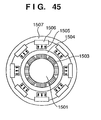
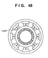
- Figs. 45 to 48 are views showing the arrangement of a linear motor according to the thirteenth embodiment of the present invention.
- Fig. 45 is a sectional view taken along the line of arrows A - A of Fig. 48
- Fig. 48 is a sectional view of the linear motor taken along the driving axis.
- a multilayered yoke 1503 of the stator is formed of eight arcuated multilayered yoke members 1503a, and magnet arrays 1505 and back yokes 1506 of the movable element form eight units.
- the magnet arrays 1505 and back yokes 1506 form eight sets, the eight sets of magnet arrays 1505 and back yokes 1506 are held by a cylindrical holding member 1507.
- the holding member 1507 is preferably made of a ceramic material or the like with a high rigidity.
- the region where the coil arrays and magnet arrays face each other becomes larger than in the twelfth embodiment, so the thrust is increased.
- the linear motor of this embodiment can be used in a stage apparatus and various types of apparatuses, e.g., an exposure apparatus, including a stage apparatus.
- Figs. 49 and 50 are views showing the arrangement of a linear motor according to the fourteenth embodiment of the present invention.
- Fig. 49 is a sectional view taken along the line of arrows A - A of Fig. 50
- Fig. 50 is a sectional view of the linear motor taken along the driving axis.
- a coil array 1604 of the stator is formed to include four smooth convex surfaces.
- Magnet arrays 1605 of the movable element, a multilayered yoke 1603 of the stator, and a central support member 1601 also have shapes matching the shape of the coil array 1604.
- This embodiment has both the advantages of the first to eleventh embodiments and that of the twelfth embodiment.
- the first to eleventh embodiments are advantageous in that that region of the coil array which faces the magnet array is larger than that of the twelfth embodiment.
- the twelfth embodiment is advantageous in that, since its coil array forms an annular shape, a change in tension does not occur during winding the windings of the coil array, so the productivity of the coils improves, and the shape precisions of the coils improves.
- This embodiment may be slightly inferior to the twelfth embodiment in that its coil array 1604 includes four smooth convex surfaces (curved surfaces), as described above.
- its coil array 1604 includes four smooth convex surfaces (curved surfaces), as described above.
- the coil windings can be wound at a high speed, and variations in shape of the coils are small.
- the width of the yoke of the stator can be widened to near the corners, so the utilizing efficiency of the coil is increased.
- the linear motor of this embodiment can be used in a stage apparatus or various types of apparatuses, e.g., an exposure apparatus, including a stage apparatus.
- linear motor represented by each of the various embodiments described above, and a stage utilizing such a linear motor can be utilized as part of an apparatus, e. g. , a wafer stage or reticle stage, that forms an exposure apparatus for manufacturing a device such as a semiconductor device or microdevice.
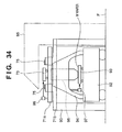
- FIG. 34 An embodiment of a scanning exposure apparatus in which a stage using either one of the linear motors of the embodiments described above as a reticle stage or wafer stage will be described with reference to Fig. 34 .
- a reticle stage base 71a for supporting a reticle stage 73 is integral with a frame 94 standing upright on a base plate 92 which supports a wafer stage 93 of the exposure apparatus.
- a linear motor base 71b is supported by a support frame 90 directly fixed to a floor surface F separately from the base plate 92.
- An exposure beam transmitted through a reticle on the reticle stage 73 to expose a wafer W on the wafer stage 93 is generated by a light source unit 95 indicated by a broken line.
- the frame 94 supports the reticle stage base 71a, and supports a projection optical system 96 between the reticle stage 73 and wafer stage 93.
- a stator 75 of a linear motor for accelerating or decelerating the reticle stage 73 is supported by the support frame 90 which is separate from the frame 94. Hence, the reactive force of the driving force of the linear motor for the reticle stage 73 will not be transmitted to the wafer stage 93 to serve as a disturbance to the driving portion, or to vibrate the projection optical system 96.
- the wafer stage 93 is scanned by the driving portion in synchronism with the reticle stage 73.
- their positions are continuously detected by interferometers 97 and 98 and are fed back to the driving portions of the reticle stage 73 and wafer stage 93. Therefore, the scanning start positions of the reticle stage 73 and wafer stage 93 can be precisely synchronized with each other, and the scanning speed in a constant-speed scanning region can be controlled at a high precision.
- Fig. 35 shows a flow of the fabrication of a semiconductor device (a semiconductor chip such as an IC or LSI, a liquid crystal panel, a CCD, a thin filmmagnetic head, a micromachine, and the like).
- a semiconductor device a semiconductor chip such as an IC or LSI, a liquid crystal panel, a CCD, a thin filmmagnetic head, a micromachine, and the like.
- step S1 circuit designing
- step S2 mask fabrication
- a mask where the designed circuit pattern is formed is fabricated.
- step S3 wafer fabrication
- a wafer as a substrate is fabricated using a material such as silicon or the like.
- step S4 wafer process
- preprocess wafer process
- step S5 assembly process
- step S5 packaging process
- step S6 inspections such as an operation test and durability test are performed on the semiconductor device fabricated in step S5.
- the semiconductor device is completed through these processes, and is shipped (step S7).
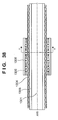
- Fig. 36 shows a more detailed flow of the wafer process.
- step S11 oxidation
- step S12 CVD
- step S13 electrode formation
- step S14 ion implantation
- step S15 resist processing
- step S16 exposure
- step S17 development
- step S18 etching
- step S19 resist stripping
- the resist unnecessary after the etching is removed.
- a linear motor having a structure that can be fabricated easily, and a stage apparatus and exposure apparatus having this linear motor can be provided.
Landscapes
- Physics & Mathematics (AREA)
- Engineering & Computer Science (AREA)
- Chemical & Material Sciences (AREA)
- Combustion & Propulsion (AREA)
- Electromagnetism (AREA)
- Power Engineering (AREA)
- General Physics & Mathematics (AREA)
- Linear Motors (AREA)
Claims (35)
- Moteur linéaire comportant un stator et un élément mobile, caractérisé en ce que
ledit stator comporte un élément de support (101), une culasse de stator (103) comprenant une pluralité d'éléments de culasse de type plaque (103a), et une bobine de stator agencée à l'extérieur de ladite culasse de stator et comportant une pluralité de bobines de stator partielles (104) agencées le long d'une direction d'un axe dudit stator, ladite pluralité d'éléments de culasse de type plaque (103a) étant fixées à des surfaces externes dudit élément de support (101) afin de former, aux angles de ladite culasse de stator (103), des premiers espaces où ladite pluralité d'éléments de culasse de type plaque (103a) ne sont pas présents,
ledit élément mobile est agencé à l'extérieur de ladite bobine de stator,
ledit élément mobile comprend une pluralité de culasses arrière de type plaque (106) sur lesquelles une pluralité de matrices d'aimants (105) sont respectivement agencées, ledit élément mobile étant formé en assemblant ladite pluralité de culasses arrière de type plaque (106) de manière que ledit élément mobile ait une forme en section transversale sensiblement polygonale et ladite pluralité de matrices d'aimants (105) soient agencées à l'intérieur dudit élément mobile de manière à former, aux angles latéraux internes dudit élément mobile, des seconds espaces où ladite pluralité de matrices d'aimants (105) ne sont pas présentes,
ladite bobine de stator comporte des parties plates, chacune étant parallèle à l'une des culasses de ladite pluralité de culasses arrière de type plaque (106) et l'un des éléments de ladite pluralité d'éléments de culasse de type plaque (103a), et
chacun des fils conducteurs extrait de ladite pluralité de bobines de stator partielles (104) est agencé pour s'étendre à proximité d'une limite d'une partie plate et d'une autre partie plate de ladite bobine de stator le long de l'axe dudit stator, en utilisant ledit premier espace et/ou ledit second espace. - Moteur linéaire selon la revendication 1, dans lequel ledit élément de culasse de type plaque (103a) comporte une structure multicouche formée en empilant un grand nombre de couches perpendiculaires à une surface dudit élément de culasse de type plaque (103a) et parallèles à l'axe dudit stator.
- Moteur linéaire selon la revendication 1, dans lequel ladite culasse de stator a une structure en prisme.
- Moteur linéaire selon la revendication 1, dans lequel une partie de début d'enroulement de chaque bobine de ladite pluralité de bobines de stator partielles (104) est située à proximité de la limite de ladite bobine de stator.
- Moteur linéaire selon la revendication 1, dans lequel une partie de fin d'enroulement de chaque bobine de ladite pluralité de bobines de stator partielles (104) est située à proximité de la limite de ladite bobine de stator.
- Moteur linéaire selon la revendication 1, dans lequel une partie de fin d'enroulement et une partie de début d'enroulement de chaque bobine de ladite pluralité de bobines de stator partielles (104) sont situées à proximité de la limite de ladite bobine de stator.
- Moteur linéaire selon la revendication 1, dans lequel les parties plates de ladite bobine de stator sont au nombre de quatre.
- Moteur linéaire selon la revendication 1, dans lequel les parties plates de ladite bobine de stator sont au nombre de trois.
- Moteur linéaire selon la revendication 1, dans lequel ledit élément de support comporte un canal d'écoulement en son sein, par lequel un réfrigérant doit s'écouler.
- Moteur linéaire selon la revendication 9, dans lequel le canal d'écoulement présente une section circulaire.
- Moteur linéaire selon la revendication 9, dans lequel le canal d'écoulement comprend une pluralité de canaux d'écoulement formés dans ledit élément de support.
- Moteur linéaire selon la revendication 9, dans lequel le canal d'écoulement comporte une pluralité de rainures agencées radialement autour de l'axe dudit stator en tant que centre.
- Moteur linéaire selon la revendication 9, dans lequel le canal d'écoulement présente une section en nid d'abeille.
- Moteur linéaire selon la revendication 1, dans lequel ledit élément de support est constitué de métal.
- Moteur linéaire selon la revendication 1, dans lequel ledit élément de support est constitué de céramique.
- Moteur linéaire selon la revendication 1, dans lequel une cloison est agencée entre ladite bobine de stator dudit stator et ledit aimant mobile dudit élément mobile, et un canal d'écoulement par lequel un réfrigérant doit s'écouler est formé entre ladite bobine de stator et la cloison.
- Moteur linéaire selon la revendication 16, dans lequel la cloison présente une section polygonale.
- Moteur linéaire selon la revendication 16, dans lequel la cloison présente une section circulaire.
- Moteur linéaire selon la revendication 18, dans lequel la cloison est constituée d'un matériau isolant.
- Moteur linéaire selon la revendication 1, dans lequel ledit stator comporte un élément d'alignement pour aligner ladite pluralité de bobines de stator partielles.
- Moteur linéaire selon la revendication 20, dans lequel ledit élément d'alignement présente une forme en dents de peigne à une de ses sections prise le long d'une direction de l'axe dudit stator, et lesdites bobines de stator partielles sont alignées parmi les dents de peigne qui constituent la forme en dents de peigne.
- Moteur linéaire selon la revendication 1, dans lequel chaque bobine de ladite pluralité de bobines de stator partielles est enroulée sur un fuseau.
- Moteur linéaire selon la revendication 22, dans lequel le fuseau comporte une encoche dans une plaque latérale.
- Moteur linéaire selon la revendication 22, dans lequel une plaque latérale du fuseau a une épaisseur supérieure à la moitié d'un diamètre d'un enroulement de ladite bobine de stator.
- Moteur linéaire selon la revendication 1, comportant un couvercle anti-libération de gaz à l'extérieur de ladite bobine de stator.
- Moteur linéaire selon la revendication 1, dans lequel ladite pluralité de culasses arrière de type plaque (106) sont supportées par un élément de support.
- Appareil à porte-objet comprenant
le moteur linéaire selon la revendication 1, et
un porte-objet entraîné par le moteur linéaire. - Appareil à porte-objet selon la revendication 27, comprenant, en outre
un élément masse relié à un stator du moteur linéaire, et
une plaque surface pour supporter, en glissement, une structure comprenant ledit stator et ledit élément masse. - Appareil à porte-objet selon la revendication 28, dans lequel ledit élément masse est agencé pour entourer ledit stator et ledit élément mobile du moteur linéaire.
- Appareil à porte-objet selon la revendication 29, dans lequel ledit élément masse comporte un canal d'écoulement en son sein, par lequel un réfrigérant doit s'écouler.
- Appareil à porte-objet selon la revendication 28, dans lequel
ledit élément mobile comporte un corps de réflexion au moins sur sa surface qui est tournée vers ledit stator, et
ledit élément masse comporte un corps d'absorption au moins sur sa surface qui est tournée vers ledit stator. - Appareil d'exposition qui comporte l'appareil à porte-objet selon la revendication 27 en tant qu'appareil à porte-objet pour aligner un substrat.
- Appareil d'exposition qui comporte l'appareil à porte-objet selon la revendication 27 en tant qu'appareil à porte-objet pour aligner un original.
- Procédé de fabrication de dispositif comprenant les étapes consistant à :exposer une plaquette avec un motif de dispositif en utilisant l'appareil d'exposition selon la revendication 32, etdévelopper la plaque exposée.
- Procédé de fabrication de dispositif comprenant les étapes consistant à :exposer une plaquette avec un motif de dispositif en utilisant l'appareil d'exposition selon la revendication 33, etdévelopper la plaque exposée.
Applications Claiming Priority (4)
| Application Number | Priority Date | Filing Date | Title |
|---|---|---|---|
| JP2001310052A JP3890213B2 (ja) | 2001-10-05 | 2001-10-05 | リニアモータ、ステージ装置及び露光装置 |
| JP2001310053A JP2003116261A (ja) | 2001-10-05 | 2001-10-05 | リニアモータ、ステージ装置及び露光装置 |
| JP2001310052 | 2001-10-05 | ||
| JP2001310053 | 2001-10-05 |
Publications (3)
| Publication Number | Publication Date |
|---|---|
| EP1300932A2 EP1300932A2 (fr) | 2003-04-09 |
| EP1300932A3 EP1300932A3 (fr) | 2004-04-28 |
| EP1300932B1 true EP1300932B1 (fr) | 2013-12-18 |
Family
ID=26623761
Family Applications (1)
| Application Number | Title | Priority Date | Filing Date |
|---|---|---|---|
| EP02256825.7A Expired - Lifetime EP1300932B1 (fr) | 2001-10-05 | 2002-10-01 | Moteur linéaire, support et systéme d'exposition pourvu de ce moteur linéaire |
Country Status (2)
| Country | Link |
|---|---|
| US (1) | US6864602B2 (fr) |
| EP (1) | EP1300932B1 (fr) |
Cited By (2)
| Publication number | Priority date | Publication date | Assignee | Title |
|---|---|---|---|---|
| CN106160399A (zh) * | 2015-05-12 | 2016-11-23 | 艾塔尔公司 | 短行程的线性电动机 |
| WO2023171306A1 (fr) * | 2022-03-08 | 2023-09-14 | Mitsubishi Electric Corporation | Ensemble moteur pour moteur à entraînement direct linéaire |
Families Citing this family (49)
| Publication number | Priority date | Publication date | Assignee | Title |
|---|---|---|---|---|
| JP4323759B2 (ja) * | 2002-05-27 | 2009-09-02 | キヤノン株式会社 | 露光装置およびデバイス製造方法 |
| JP3849932B2 (ja) | 2002-08-12 | 2006-11-22 | キヤノン株式会社 | 移動ステージ装置 |
| JP3826087B2 (ja) * | 2002-08-30 | 2006-09-27 | キヤノン株式会社 | 位置決め装置、荷電粒子線露光装置 |
| JP2006504378A (ja) * | 2002-10-25 | 2006-02-02 | コーニンクレッカ フィリップス エレクトロニクス エヌ ヴィ | リニアモータ |
| JP2004172557A (ja) | 2002-11-22 | 2004-06-17 | Canon Inc | ステージ装置及びその制御方法 |
| JP4227452B2 (ja) * | 2002-12-27 | 2009-02-18 | キヤノン株式会社 | 位置決め装置、及びその位置決め装置を利用した露光装置 |
| JP4194383B2 (ja) * | 2003-02-13 | 2008-12-10 | キヤノン株式会社 | リニアモータ |
| JP2004335492A (ja) * | 2003-03-07 | 2004-11-25 | Junji Kido | 有機電子材料の塗布装置およびそれを使用した有機電子素子の製造方法 |
| EP1457826A1 (fr) * | 2003-03-11 | 2004-09-15 | ASML Netherlands B.V. | Appareil lithographique et procédé pour la production d'un dispositif |
| EP1639407A4 (fr) * | 2003-06-02 | 2011-01-05 | Seiko Epson Corp | Ecrans d'aeration graves |
| JP2004364392A (ja) * | 2003-06-03 | 2004-12-24 | Canon Inc | リニアモータ、及びこれを備えるステージ装置、露光装置並びにデバイス製造方法 |
| DE10329651A1 (de) | 2003-07-01 | 2005-02-10 | Siemens Ag | Polygonartige Bauform eines Linearmotors mit Ringwicklung |
| DE10330506A1 (de) * | 2003-07-05 | 2005-03-31 | Leica Microsystems Semiconductor Gmbh | Vorrichtung zur Waferinspektion |
| JP4241295B2 (ja) * | 2003-09-26 | 2009-03-18 | キヤノン株式会社 | ステージ装置 |
| JP2005142501A (ja) * | 2003-11-10 | 2005-06-02 | Canon Inc | ステージ装置および露光装置ならびにデバイス製造方法 |
| DE112004002360B4 (de) * | 2003-12-09 | 2017-12-14 | Toshiba Kikai K.K. | Kernloser Linearmotor |
| JP2005260183A (ja) * | 2004-03-15 | 2005-09-22 | Canon Inc | 移動装置及び露光装置 |
| JP2005294468A (ja) * | 2004-03-31 | 2005-10-20 | Canon Inc | 位置決め装置、露光装置及びデバイス製造方法 |
| US7135792B2 (en) * | 2004-05-12 | 2006-11-14 | Dexter Magnetic Technologies, Inc. | High field voice coil motor |
| CN100521468C (zh) * | 2004-08-20 | 2009-07-29 | 清华大学 | 永磁同步平面电动机 |
| US7279812B2 (en) * | 2005-01-18 | 2007-10-09 | Hewlett-Packard Development Company, L.P. | Light direction assembly shorted turn |
| US8074579B1 (en) * | 2005-08-22 | 2011-12-13 | Dumitru Bojiuc | Magnetically levitated transport system |
| JP2007312516A (ja) * | 2006-05-18 | 2007-11-29 | Canon Inc | 駆動装置、露光装置及びデバイス製造方法 |
| JP4617279B2 (ja) * | 2006-08-10 | 2011-01-19 | 信越化学工業株式会社 | 磁気回路および磁場印加方法 |
| TWI460966B (zh) * | 2009-01-23 | 2014-11-11 | Hitachi Metals Ltd | Moving elements and linear motors |
| CN102460262A (zh) * | 2009-06-04 | 2012-05-16 | 株式会社尼康 | 透镜单元及摄像装置 |
| RU2012126510A (ru) * | 2009-11-14 | 2013-12-20 | Алексей СТАДНИК | Электрический привод (варианты) |
| WO2011059993A2 (fr) * | 2009-11-14 | 2011-05-19 | Alexei Stadnik | Machines électriques sans fer à réducteur de courants de foucault |
| DE102010004642B4 (de) * | 2010-01-13 | 2012-09-27 | Integrated Dynamics Engineering Gmbh | Magnetaktor sowie Verfahren zu dessen Montage |
| GB2477972B (en) * | 2010-02-20 | 2014-08-27 | Hugh-Peter Granville Kelly | Resistance training apparatus |
| US9325232B1 (en) | 2010-07-22 | 2016-04-26 | Linear Labs, Inc. | Method and apparatus for power generation |
| AU2011316872B2 (en) | 2010-10-22 | 2016-08-04 | Linear Labs, Inc. | An improved magnetic motor |
| WO2013070568A2 (fr) * | 2011-11-10 | 2013-05-16 | Nikon Corporation | Système et procédé de gestion de température d'un ensemble de réaction |
| WO2014036567A1 (fr) | 2012-09-03 | 2014-03-06 | Linear Labs, Inc. | Transducteur amélioré et procédé de fonctionnement |
| CN102944979A (zh) * | 2012-11-02 | 2013-02-27 | 清华大学 | 一种具有永磁重力补偿结构的微动台 |
| CN103066894B (zh) * | 2012-12-12 | 2015-05-20 | 清华大学 | 一种六自由度磁悬浮工件台 |
| US9473009B2 (en) * | 2013-04-18 | 2016-10-18 | Nucleus Scientific, Inc. | Permanent magnet linear actuators |
| KR101587423B1 (ko) * | 2013-08-23 | 2016-02-03 | 한국전기연구원 | 토크 맥동 저감을 위한 비대칭 자극 형상을 가지는 전기기기 |
| US9843249B2 (en) * | 2014-04-16 | 2017-12-12 | Nucleus Scientific Inc. | Magnetic position coupling and valve mechanism |
| KR20170060114A (ko) | 2014-09-24 | 2017-05-31 | 택션 테크놀로지 인코포레이티드 | 오디오-주파수 진동들에 대해 댐핑된 전자기적으로 작동된 평면형 모션을 생성하기 위한 시스템들 및 방법들 |
| US10573139B2 (en) | 2015-09-16 | 2020-02-25 | Taction Technology, Inc. | Tactile transducer with digital signal processing for improved fidelity |
| CN105375733A (zh) * | 2015-11-17 | 2016-03-02 | 广东工业大学 | 一种单缸直线式永磁发电机 |
| CN106300875A (zh) * | 2016-08-30 | 2017-01-04 | 吉林大学 | 捆绑式直线电机作动器 |
| EP4427953A2 (fr) | 2016-09-13 | 2024-09-11 | Indigo Technologies, Inc. | Système d'entraînement électrique à liaison à barres multiples |
| CN109361305A (zh) * | 2018-12-12 | 2019-02-19 | 宋局 | 一种双层共轭棒式直线电机的结构 |
| EP3667880A1 (fr) * | 2018-12-14 | 2020-06-17 | KONE Corporation | Moteur électrique linéaire, ascenseur, et procédé de commande de rotation d'une machine motrice par rapport à un faisceau de stator d'un moteur électrique linéaire |
| NL2022467B1 (en) * | 2019-01-28 | 2020-08-18 | Prodrive Tech Bv | Position sensor for long stroke linear permanent magnet motor |
| CN114787681B (zh) * | 2019-12-12 | 2024-06-04 | 华为技术有限公司 | 可进行多级移动的音圈驱动器 |
| CN114583916A (zh) * | 2022-03-24 | 2022-06-03 | 亚龙智能装备集团股份有限公司 | 一种直线电机模组 |
Family Cites Families (35)
| Publication number | Priority date | Publication date | Assignee | Title |
|---|---|---|---|---|
| US3610970A (en) * | 1967-07-18 | 1971-10-05 | Westinghouse Electric Corp | Energy converter |
| US3800172A (en) * | 1972-11-10 | 1974-03-26 | Oster J Mfg Co | Hair clipper having blade illumination and field wire strain relief |
| US4528466A (en) * | 1979-03-29 | 1985-07-09 | Papst Motoren Kg | Components for polyphase linear motors |
| US4427907A (en) * | 1981-11-23 | 1984-01-24 | Electric Power Research Institute, Inc. | Spiral pancake armature winding module for a dynamoelectric machine |
| US4870310A (en) * | 1988-03-02 | 1989-09-26 | Triplett Billy R | Portable crash-survivable kinetic energy storage machine |
| US5684856A (en) * | 1991-09-18 | 1997-11-04 | Canon Kabushiki Kaisha | Stage device and pattern transfer system using the same |
| US5402680A (en) * | 1991-12-10 | 1995-04-04 | Canon Kabushiki Kaisha | Velocity sensor and semiconductor exposing apparatus using such a sensor |
| JP2901424B2 (ja) * | 1992-08-06 | 1999-06-07 | 住友重機械工業株式会社 | 低速ギヤドモータ |
| KR100282055B1 (ko) * | 1993-03-30 | 2001-02-15 | 이데이 노부유끼 | 전자구동장치 및 전자구동장치를 이용한 포커스 제어장치 |
| JPH07115056A (ja) * | 1993-10-15 | 1995-05-02 | Canon Inc | 縦型基板ステージ装置 |
| JP3363662B2 (ja) * | 1994-05-19 | 2003-01-08 | キヤノン株式会社 | 走査ステージ装置およびこれを用いた露光装置 |
| JP3815750B2 (ja) * | 1995-10-09 | 2006-08-30 | キヤノン株式会社 | ステージ装置、ならびに前記ステージ装置を用いた露光装置およびデバイス製造方法 |
| JPH09182410A (ja) * | 1995-12-20 | 1997-07-11 | Minolta Co Ltd | リニアモータ |
| US6109767A (en) * | 1996-03-29 | 2000-08-29 | Minnesota Mining And Manufacturing Company | Honeycomb light and heat trap for projector |
| JP3548353B2 (ja) * | 1996-10-15 | 2004-07-28 | キヤノン株式会社 | ステージ装置およびこれを用いた露光装置ならびにデバイス製造方法 |
| JPH10169538A (ja) * | 1996-12-05 | 1998-06-23 | Kansai Electric Power Co Inc:The | 発電用水車のガイドベーン制御装置 |
| US6128069A (en) * | 1997-03-13 | 2000-10-03 | Canon Kabushiki Kaisha | Stage mechanism for exposure apparatus |
| JP3215655B2 (ja) * | 1997-08-07 | 2001-10-09 | 松下冷機株式会社 | リニアモータ |
| JPH1198811A (ja) * | 1997-09-24 | 1999-04-09 | Canon Inc | リニアモータ、これを用いたステージ装置や露光装置、ならびにデバイス製造方法 |
| JP3630964B2 (ja) * | 1997-12-26 | 2005-03-23 | キヤノン株式会社 | ステージ装置、およびこれを用いた露光装置ならびにデバイス製造方法 |
| JPH11191585A (ja) * | 1997-12-26 | 1999-07-13 | Canon Inc | ステージ装置、およびこれを用いた露光装置、ならびにデバイス製造方法 |
| JP3526202B2 (ja) * | 1998-02-03 | 2004-05-10 | キヤノン株式会社 | ステージ装置、およびこれを用いた露光装置、ならびにデバイス製造方法 |
| JPH11307430A (ja) * | 1998-04-23 | 1999-11-05 | Canon Inc | 露光装置およびデバイス製造方法ならびに駆動装置 |
| US6013959A (en) * | 1998-06-01 | 2000-01-11 | Eaton Corporation | Lamination structure for an electromagnetic device |
| JP3869938B2 (ja) * | 1998-06-05 | 2007-01-17 | キヤノン株式会社 | ステージ装置、露光装置、およびデバイス製造方法 |
| JP3945916B2 (ja) * | 1998-09-04 | 2007-07-18 | 三洋電機株式会社 | 可動鉄心型リニアモータ |
| JP3907357B2 (ja) * | 1998-11-12 | 2007-04-18 | キヤノン株式会社 | 段差付きコイル製造方法 |
| GB2343997B (en) * | 1998-11-23 | 2003-06-25 | Linear Drives Ltd | Coaxial linear motor for extended travel |
| US6242823B1 (en) * | 1999-02-05 | 2001-06-05 | Wayne Griswold | Linear electric machine |
| US6114781A (en) * | 1999-02-26 | 2000-09-05 | Nikon Corporation | Cooling system for a linear or planar motor |
| US6163091A (en) * | 1999-07-06 | 2000-12-19 | Nikon Corporation | Linear motor with commutation coil |
| US6271606B1 (en) * | 1999-12-23 | 2001-08-07 | Nikon Corporation | Driving motors attached to a stage that are magnetically coupled through a chamber |
| US6492756B1 (en) * | 2000-04-05 | 2002-12-10 | Wavecrest Laboratories, Llc | Rotary electric motor having magnetically isolated stator and rotor groups |
| US6365993B1 (en) * | 2000-04-07 | 2002-04-02 | Eaton Corporation | Round linear actuator utilizing flat permanent magnets |
| DE10150520B4 (de) * | 2000-10-31 | 2006-08-24 | Janke Engineering Gmbh | Elektrische Maschine |
-
2002
- 2002-10-01 EP EP02256825.7A patent/EP1300932B1/fr not_active Expired - Lifetime
- 2002-10-07 US US10/265,440 patent/US6864602B2/en not_active Expired - Lifetime
Cited By (2)
| Publication number | Priority date | Publication date | Assignee | Title |
|---|---|---|---|---|
| CN106160399A (zh) * | 2015-05-12 | 2016-11-23 | 艾塔尔公司 | 短行程的线性电动机 |
| WO2023171306A1 (fr) * | 2022-03-08 | 2023-09-14 | Mitsubishi Electric Corporation | Ensemble moteur pour moteur à entraînement direct linéaire |
Also Published As
| Publication number | Publication date |
|---|---|
| EP1300932A3 (fr) | 2004-04-28 |
| EP1300932A2 (fr) | 2003-04-09 |
| US6864602B2 (en) | 2005-03-08 |
| US20030102723A1 (en) | 2003-06-05 |
Similar Documents
| Publication | Publication Date | Title |
|---|---|---|
| EP1300932B1 (fr) | Moteur linéaire, support et systéme d'exposition pourvu de ce moteur linéaire | |
| US6987335B2 (en) | Alignment apparatus and exposure apparatus using the same | |
| US6107703A (en) | Linear motor mechanism for exposure apparatus, and device manufacturing method using the same | |
| US7075197B2 (en) | Aligning apparatus, exposure apparatus, and device manufacturing method | |
| US6313551B1 (en) | Magnet array for a shaft-type linear motor | |
| US20020089237A1 (en) | Electric linear motor | |
| US6873404B2 (en) | Stage apparatus and method of driving the same | |
| US7282821B2 (en) | Linear motor, stage apparatus, exposure apparatus, and device manufacturing apparatus | |
| US7414336B2 (en) | Dual flow circulation system for a mover | |
| US8044541B2 (en) | Multi-degree-of-freedom actuator and stage device | |
| US6043572A (en) | Linear motor, stage device, and exposing device | |
| WO2013112761A2 (fr) | Moteur plat à groupements de conducteurs asymétriques | |
| JP3890213B2 (ja) | リニアモータ、ステージ装置及び露光装置 | |
| JP2003116261A (ja) | リニアモータ、ステージ装置及び露光装置 | |
| US6025658A (en) | Linear motor, and stage apparatus and exposure apparatus using the same | |
| US11843300B2 (en) | Linear motor, transport apparatus, and production apparatus | |
| JP4418710B2 (ja) | ステージ装置 | |
| US7408276B2 (en) | Plane motor device with surrounding member surrounding coil unit and with cooling channel provided within surrounding member | |
| JPH10149976A (ja) | ステージ装置およびこれを用いた露光装置 | |
| US20050174551A1 (en) | Position control and heat dissipation for photolithography systems | |
| US12021432B2 (en) | Actuator device for use in a positioning system as well as such positioning system | |
| US20240055970A1 (en) | Linear motor, transport apparatus, and production apparatus | |
| EP4270423A1 (fr) | Dispositif électromagnétique, appareil d'alignement et procédé de fabrication d'article | |
| JP3715742B2 (ja) | 静圧ステージ | |
| JP2024017697A (ja) | 電機子、冷却ユニットおよびリニアモータ |
Legal Events
| Date | Code | Title | Description |
|---|---|---|---|
| PUAI | Public reference made under article 153(3) epc to a published international application that has entered the european phase |
Free format text: ORIGINAL CODE: 0009012 |
|
| AK | Designated contracting states |
Kind code of ref document: A2 Designated state(s): AT BE BG CH CY CZ DE DK EE ES FI FR GB GR IE IT LI LU MC NL PT SE SK TR |
|
| AX | Request for extension of the european patent |
Extension state: AL LT LV MK RO SI |
|
| PUAL | Search report despatched |
Free format text: ORIGINAL CODE: 0009013 |
|
| AK | Designated contracting states |
Kind code of ref document: A3 Designated state(s): AT BE BG CH CY CZ DE DK EE ES FI FR GB GR IE IT LI LU MC NL PT SE SK TR |
|
| AX | Request for extension of the european patent |
Extension state: AL LT LV MK RO SI |
|
| 17P | Request for examination filed |
Effective date: 20040913 |
|
| AKX | Designation fees paid |
Designated state(s): DE FR GB IT NL |
|
| 17Q | First examination report despatched |
Effective date: 20120709 |
|
| GRAP | Despatch of communication of intention to grant a patent |
Free format text: ORIGINAL CODE: EPIDOSNIGR1 |
|
| INTG | Intention to grant announced |
Effective date: 20130701 |
|
| RIN1 | Information on inventor provided before grant (corrected) |
Inventor name: KORENAGA, NOBUSHIGE |
|
| GRAS | Grant fee paid |
Free format text: ORIGINAL CODE: EPIDOSNIGR3 |
|
| GRAA | (expected) grant |
Free format text: ORIGINAL CODE: 0009210 |
|
| AK | Designated contracting states |
Kind code of ref document: B1 Designated state(s): DE FR GB IT NL |
|
| REG | Reference to a national code |
Ref country code: GB Ref legal event code: FG4D |
|
| REG | Reference to a national code |
Ref country code: DE Ref legal event code: R096 Ref document number: 60245853 Country of ref document: DE Effective date: 20140206 |
|
| REG | Reference to a national code |
Ref country code: NL Ref legal event code: T3 |
|
| REG | Reference to a national code |
Ref country code: DE Ref legal event code: R097 Ref document number: 60245853 Country of ref document: DE |
|
| PLBE | No opposition filed within time limit |
Free format text: ORIGINAL CODE: 0009261 |
|
| STAA | Information on the status of an ep patent application or granted ep patent |
Free format text: STATUS: NO OPPOSITION FILED WITHIN TIME LIMIT |
|
| 26N | No opposition filed |
Effective date: 20140919 |
|
| REG | Reference to a national code |
Ref country code: DE Ref legal event code: R097 Ref document number: 60245853 Country of ref document: DE Effective date: 20140919 |
|
| GBPC | Gb: european patent ceased through non-payment of renewal fee |
Effective date: 20141001 |
|
| PG25 | Lapsed in a contracting state [announced via postgrant information from national office to epo] |
Ref country code: GB Free format text: LAPSE BECAUSE OF NON-PAYMENT OF DUE FEES Effective date: 20141001 |
|
| REG | Reference to a national code |
Ref country code: FR Ref legal event code: ST Effective date: 20150630 |
|
| PG25 | Lapsed in a contracting state [announced via postgrant information from national office to epo] |
Ref country code: FR Free format text: LAPSE BECAUSE OF NON-PAYMENT OF DUE FEES Effective date: 20141031 |
|
| PGFP | Annual fee paid to national office [announced via postgrant information from national office to epo] |
Ref country code: NL Payment date: 20150908 Year of fee payment: 14 |
|
| PG25 | Lapsed in a contracting state [announced via postgrant information from national office to epo] |
Ref country code: IT Free format text: LAPSE BECAUSE OF FAILURE TO SUBMIT A TRANSLATION OF THE DESCRIPTION OR TO PAY THE FEE WITHIN THE PRESCRIBED TIME-LIMIT Effective date: 20131218 |
|
| REG | Reference to a national code |
Ref country code: NL Ref legal event code: MM Effective date: 20161101 |
|
| PG25 | Lapsed in a contracting state [announced via postgrant information from national office to epo] |
Ref country code: NL Free format text: LAPSE BECAUSE OF NON-PAYMENT OF DUE FEES Effective date: 20161101 |
|
| PGFP | Annual fee paid to national office [announced via postgrant information from national office to epo] |
Ref country code: DE Payment date: 20181228 Year of fee payment: 17 |
|
| REG | Reference to a national code |
Ref country code: DE Ref legal event code: R119 Ref document number: 60245853 Country of ref document: DE |
|
| PG25 | Lapsed in a contracting state [announced via postgrant information from national office to epo] |
Ref country code: DE Free format text: LAPSE BECAUSE OF NON-PAYMENT OF DUE FEES Effective date: 20200501 |