EP1295723B1 - Tintenpatrone und Verfahren zu ihrer Herstellung - Google Patents
Tintenpatrone und Verfahren zu ihrer Herstellung Download PDFInfo
- Publication number
- EP1295723B1 EP1295723B1 EP02021260A EP02021260A EP1295723B1 EP 1295723 B1 EP1295723 B1 EP 1295723B1 EP 02021260 A EP02021260 A EP 02021260A EP 02021260 A EP02021260 A EP 02021260A EP 1295723 B1 EP1295723 B1 EP 1295723B1
- Authority
- EP
- European Patent Office
- Prior art keywords
- ink
- container body
- ink supply
- porous member
- ink cartridge
- Prior art date
- Legal status (The legal status is an assumption and is not a legal conclusion. Google has not performed a legal analysis and makes no representation as to the accuracy of the status listed.)
- Expired - Lifetime
Links
- 238000004519 manufacturing process Methods 0.000 title claims description 21
- 238000003780 insertion Methods 0.000 claims description 8
- 230000037431 insertion Effects 0.000 claims description 8
- 238000007789 sealing Methods 0.000 claims 1
- 230000003014 reinforcing effect Effects 0.000 description 7
- 239000000463 material Substances 0.000 description 6
- 239000011148 porous material Substances 0.000 description 6
- 238000010586 diagram Methods 0.000 description 5
- 238000000034 method Methods 0.000 description 4
- 230000000694 effects Effects 0.000 description 3
- 230000006835 compression Effects 0.000 description 2
- 238000007906 compression Methods 0.000 description 2
- 239000003086 colorant Substances 0.000 description 1
- 230000001419 dependent effect Effects 0.000 description 1
- 238000001914 filtration Methods 0.000 description 1
- 230000001105 regulatory effect Effects 0.000 description 1
- 230000002787 reinforcement Effects 0.000 description 1
- 239000005871 repellent Substances 0.000 description 1
- 238000003466 welding Methods 0.000 description 1
Images


Classifications
-
- B—PERFORMING OPERATIONS; TRANSPORTING
- B41—PRINTING; LINING MACHINES; TYPEWRITERS; STAMPS
- B41J—TYPEWRITERS; SELECTIVE PRINTING MECHANISMS, i.e. MECHANISMS PRINTING OTHERWISE THAN FROM A FORME; CORRECTION OF TYPOGRAPHICAL ERRORS
- B41J2/00—Typewriters or selective printing mechanisms characterised by the printing or marking process for which they are designed
- B41J2/005—Typewriters or selective printing mechanisms characterised by the printing or marking process for which they are designed characterised by bringing liquid or particles selectively into contact with a printing material
- B41J2/01—Ink jet
- B41J2/17—Ink jet characterised by ink handling
- B41J2/175—Ink supply systems ; Circuit parts therefor
- B41J2/17503—Ink cartridges
- B41J2/17553—Outer structure
-
- B—PERFORMING OPERATIONS; TRANSPORTING
- B41—PRINTING; LINING MACHINES; TYPEWRITERS; STAMPS
- B41J—TYPEWRITERS; SELECTIVE PRINTING MECHANISMS, i.e. MECHANISMS PRINTING OTHERWISE THAN FROM A FORME; CORRECTION OF TYPOGRAPHICAL ERRORS
- B41J2/00—Typewriters or selective printing mechanisms characterised by the printing or marking process for which they are designed
- B41J2/005—Typewriters or selective printing mechanisms characterised by the printing or marking process for which they are designed characterised by bringing liquid or particles selectively into contact with a printing material
- B41J2/01—Ink jet
- B41J2/17—Ink jet characterised by ink handling
- B41J2/175—Ink supply systems ; Circuit parts therefor
- B41J2/17503—Ink cartridges
- B41J2/17513—Inner structure
-
- B—PERFORMING OPERATIONS; TRANSPORTING
- B41—PRINTING; LINING MACHINES; TYPEWRITERS; STAMPS
- B41J—TYPEWRITERS; SELECTIVE PRINTING MECHANISMS, i.e. MECHANISMS PRINTING OTHERWISE THAN FROM A FORME; CORRECTION OF TYPOGRAPHICAL ERRORS
- B41J2/00—Typewriters or selective printing mechanisms characterised by the printing or marking process for which they are designed
- B41J2/005—Typewriters or selective printing mechanisms characterised by the printing or marking process for which they are designed characterised by bringing liquid or particles selectively into contact with a printing material
- B41J2/01—Ink jet
- B41J2/17—Ink jet characterised by ink handling
- B41J2/175—Ink supply systems ; Circuit parts therefor
- B41J2/17503—Ink cartridges
- B41J2/17559—Cartridge manufacturing
Definitions
- the present invention relates to an ink cartridge and its manufacturing method. Particularly, the invention relates to an ink cartridge which supplies ink to an ink jet recording apparatus through an ink supply needle of the ink jet recording apparatus.
- an ink jet recording apparatus in which an ink cartridge is detachably mounted onto a carriage having an ink jet recording head thereby to supply ink.
- this ink cartridge there is an ink cartridge having an outline of an approximately rectangular parallelepiped, in which a porous member including ink therein is housed.
- a porous member including ink therein is housed.
- This type of ink cartridge is made up of a container body having a shape of an approximately rectangular parallelepiped and the opened upper surface.
- the container body is provided, at its bottom surface, with an ink supply passage into which an ink supply needle of the ink jet recording apparatus is inserted.
- the porous member is inserted into the container body from the upper surface, and the upper surface is sealed by a lid member, whereby the ink cartridge is manufactured.
- the porous member is inserted into the container body from the upper surface in order to press a portion of the porous member near the ink supply passage against the ink supply passage and the ink supply surface thereby to compress this portion of the porous member.
- an On-carriage type of inkjet recording apparatus in which an ink cartridge is mounted onto a movable carriage having an ink recording head, in order to mount as many ink cartridges as possible on the carriage, there is a tendency to reduce the width of the ink cartridge in the scanning direction of the carriage.
- a color ink jet recording apparatus can mount ink cartridges holding ink of four or more colors in order to improve color reproduction.
- the width of the ink cartridge in the carriage moving direction is made as small as possible in order to make the width of the recording apparatus small and further the height of each ink cartridge is several times as large as the width thereof in order to secure the enough ink capacity.
- the porous member For the ink cartridge that is thus high and narrow, it is difficult to insert the porous member into the container from the upper surface of the container. Namely, the porous member has compressibility, and it is not easy to insert such porous member into the narrow and long space where friction is large.
- the above ink cartridge of which the height is larger than the width thereof is weak in mechanical strength in the width direction. Namely, in the side surface of the ink cartridge, its surrounding portion is only connected to other surfaces. Therefore, regarding the side surface having the large height and large area, its central portion is not supported by any members. Consequently, in case that pressure reduction is performed by letting air out of the inside of the ink cartridge in order to make the inside of the ink cartridge in a negative pressure state, the side surface having this large area is easy to deform. In case that this deformation exceeds an allowable size of the cartridge, there is fear that the ink cartridge is broken. Further, in case that the user or the like holds the central portions of the side surfaces of the ink cartridge opposed to each other so as to pinch them, that is, in case that the strong power is applied to these portions, there is fear that the ink cartridge is broken.
- EP 0 765 756 discloses an ink cartridge having the features of the preamble of claim 1. It also discloses a manufacturing method comprising the features of the preamble of claim 12.
- US-A-5, 488, 401 describes an ink cartridge in which a porous member is kept in a more compressed state in the vicinity of an ink supply passage.
- the object underlying the invention is to bring the porous member into a more compressed state in the vicinity of the ink supply passage, while at the same time, insertion of the porous member remains easy. This object is solved by an ink cartridge according to claim 1 and the manufacturing method for an ink cartridge according to claim 12.
- a porous member in manufacture of an ink cartridge, a porous member is inserted into a container body from an opening surface side. Accordingly, insertion of the porous member is easy. Further, after a portion of the porous member near an ink supply passage is pressed against a pressure-contacting portion and compressed, the porous member is inserted into the container body. Therefore, ink collects around the ink supply passage, so that it is possible to provide an ink cartridge that supplies ink stably.
- a reinforcing structure may be provided for the inside of ink cartridge. Therefore, the mechanical strength of the ink cartridge in the width direction can be reinforced. Further, the porous member may have a shape avoiding the reinforcing structure and surrounding it. Therefore, it is possible to prevent ink from collecting unnecessarily around the reinforcing structure. As the reinforcing structure, a rib is preferable.
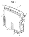
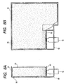
- Fig. 1 is a front perspective view of an ink cartridge according to a first embodiment of the invention.
- Fig. 2 is a rear perspective view of the ink cartridge in Fig. 1.
- An ink cartridge 10 includes a container body 12 and a lid member 14, and has an outline of an approximately rectangular parallelepiped as a whole.
- the container body 12 has an ink supply surface 18 including an ink supply passage 16 into which an ink supply needle of an ink jet recording apparatus is inserted.
- a slit portion 30 extending from the ink supply surface 18 of the container body 12 in the inserting direction of the ink supply needle.
- fitting members 32 and 34 respectively fitting to a carriage of the ink jet recording apparatus are formed integrally with the container body 12.
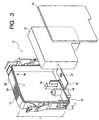
- Fig. 3 is an exploded perspective view of the ink cartridge 10 in the first embodiment.
- the ink cartridge 10 includes the above container body 12 and the lid member 14, and further includes a porous member 20 to be housed in the space formed by the container body 12 and the lid member 14, and a pressure-contacting portion 22 provided in the vicinity of the ink supply passage 16 in parallel to the ink supply surface.
- the container body 12 has a shape of an approximately rectangular parallelepiped in which one side surface is opened.
- the ink supply passage 16 communicating from the outside of the container body 12 to the inside thereof is provided on the ink supply surface 18.
- the slit portion 30 forms a convex portion extruding inward of the container body 12.
- a side surface 26 approximately orthogonal to the ink supply surface 18 of the container body 12 its height h is larger than at least one width w of the ink supply surface 18.
- the width of the ink cartridge in the carriage scanning direction is frequently made small.
- the height of the ink cartridge becomes several times as large as the width thereof.
- the height h of the container body 12 is also made several times as large as the width w thereof.
- the opening surface 28 is one of surfaces having the largest area in six surfaces constituting the approximately rectangular parallelepiped-shaped container body 12.
- the container body 12 further includes a vent hole 36 communicating with the air.
- the air is brought through this vent hole 36 into the ink cartridge 10, and ink is supplied through the ink supply passage 16 from the inside of the ink cartridge 10 to the ink jet recording apparatus.
- the vent hole 36 is preferably sealed by a film having ink-repellent property and gas-permeability.
- the vent hole 36 may be connected to a capillary so that the inside of the ink cartridge 10 is communicated with the air through the capillary.
- the lid member 14 is a plate-like member having the approximately same shape as the opening surface 28 of the container body 12.
- the lid member 14 is welded to the container body 12 and seals the opening surface 28 of the container body 12. Further, a film may be applied onto the opening surface 28 of the container body 12 and thereafter the lid member 14 may be welded to the container body 12 from the film side.
- the space inside the ink cartridge 10 can be surely sealed.
- the porous member 20 has many small pores therein, and ink is held in these small pores by the capillary power. Though this porous member 20 has a shape of a rectangular parallelepiped as described later, it is shown in Fig. 3 in a deformed state in which the porous member 20 is pressure-contacted by the pressure-contacting portion 22 and housed into the container body 12.
- the pressure-contacting portion 22 is a plate-like member provided on the ink supply passage 16 in parallel to the ink supply surface 18.
- the pressure-contacting portion 22 is a member discrete from the container body 12.
- the invention is not limited to this, but the pressure-contacting portion 22 may be molded integrally with the container body 12.
- the pressure-contacting portion 22 has, in its position corresponding to the ink supply passage 16, a filter 24 through which ink from the porous member 20 passes. This filter 24 can prevent foreign matter included in the ink from getting mixed in the ink jet recording apparatus by filtering the foreign matter.
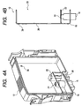
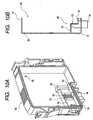
- Fig. 4A is a perspective view showing an initial state in order to explain a manufacturing method of the ink cartridge 10 in the first embodiment.
- Fig. 4B is a sectional view of a portion near an ink supply passage 16 in Fig. 4A, taken in parallel to the inserting direction of an ink needle, and Fig. 4B is shown simply in order to make the explanation easy.
- a container body 12 similarly to that shown in Fig. 3, has a shape of an approximately rectangular parallelepiped including an ink supply surface 18, in which the height of a side surface 26 approximately orthogonal to the ink supply surface 18 is larger than at least one width of the ink supply surface 18, and one of the side surfaces is opened to provide an opening-surface 28, and the container body 12 is molded integrally.
- a pressure-contacting portion 22 having a filter 24: is provided on the ink supply passage 16 in parallel to the ink supply surface 18.
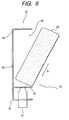
- Fig. 5 is a perspective view showing a porous member 20 to be inserted into the container body 12.
- the porous member 20 has a shape of a rectangular parallelepiped that is the approximately same as the container body 12. From Fig. 5 on, spots shown in the porous member 20 represent a density of the porous member. In the figure, a portion where spots are shown densely, in which the porous member 20 is compressed and dense, indicates that capillary power is strong.
- Fig. 6 is a sectional view showing a first step of a process for inserting the porous member 20 into the container body 12. Firstly, a portions 33 of the porous member 20 near the ink supply surface 18 is pressed toward the ink supply surface 1*8 in the direction of an arrow A. More particularly, the portion 33 of the porous member 20 is pressed from the slanting upside of the opening surface 28 against the pressure-contacting portion 22 provided in the vicinity of the ink supply passage 16 in parallel to the ink supply surface 18.
- Fig. 7 is a sectional view showing a second step of the process for inserting the porous member 20 into the container body 12.
- the portion 33 of the porous member 20 near the ink supply surface 18 is pressed in the direction of an arrow A thereby to compress more this portion 33.
- the porous member 20 has been compressed so that the height of the porous member 20 becomes the same as the length between the pressure-contacting portion 22 and the upper surface of the container body 12, the whole of the porous member 20 is inserted into the container body 12 so as to be turned in the direction of an arrow B.
- Figs. 8A and 8B show the states where the porous member 20 is housed into the container body 12.
- Fig. 8A is a sectional view
- Fig. 8B is a sectional diagram viewed from the direction orthogonal to Fig. 8A.
- the porous member 20 is pressed against the pressure-contacting portion 22 and inserted into the container body 12.
- the porous member 20 around the pressure-contacting portion 22 is compressed.
- a pore diameter of the small pore becomes small, so that the capillary power becomes stronger.
- the compressed portion is stronger in ink holding power than the no-compressed portion. Therefore, the ink held in the porous member 20 is easy to collect at the compressed portion around the pressure-contacting portion 22.
- the ink is inceimpulsly supplied from the porous member 20 through the ink supply passage 16 to the ink jet recording apparatus.
- Fig. 9 is a sectional view showing the state where a lid member 14 is attached to the container body 12. From the states shown in Figs. 8A and 8B, the lid member 14 is attached to the container body 12 so as to seal the opening portion 28. As an example of this attachment, the lid member 14 is attached to the container body 12 by vibration-welding. Hereby, the porous member 20 is housed in the sealed space.
- the ink cartridge 10 is placed in a pressure reduction room in which pressure is reduced, and the space surrounded by the container body 12 and the lid member 14 is pressure-reduced. Ink is put into the pressure-reduced space surrounded by the container body 14 and the lid member 14 from, for example, the ink supply passage 16 thereby to permit the porous member 20 to include the ink. As described above, the ink cartridge 10 is manufactured.
- the opening surface is one of the surfaces having the largest area in six surfaces constituting the approximately rectangular parallelepiped-shaped container body, and in the ink cartridge manufacturing method, the porous member is inserted into the container body from this opening surface side. Therefore, the insertion of the porous member is easy. Further, after the portion of the porous member near the ink supply passage has been pressed against the pressure-contacting portion and compressed, the porous member is inserted into the container body. Therefore, the ink collects around the ink supply passage, so that it is possible to provide an ink cartridge which supplies ink stably.
- Fig. 10A is a perspective view showing an initial state in order to explain a manufacturing method of an ink cartridge 40 in a second embodiment which is not part of the invention.
- Fig. 10B is a sectional view of a portion near an ink supply passage 46 in Fig. 10A, taken in parallel to the inserting direction of an ink needle, and Fig. 10B is shown simply in order to make the explanation easy.
- parts similar to those in the first embodiment shown in Fig. 1 are denoted by the same reference numerals.
- a pressure contacting portion 48 which is, in contrast to the invention, perpendicular to an ink supply surface 18 is provided on the ink supply passage 46.
- the pressure-contacting portion 48 has on its both sides horizontal plates 52 and 54 which are parallel to the ink supply surface 18 and different in height from each other.
- a filter 50 is provided for a portion of the pressure-contacting portion 48 corresponding to the ink supply passage 46.
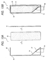
- Figs. 11A and 11B are diagram showing, step-by-step, the manufacturing method of the ink cartridge 40 in the second embodiment.
- a porous member 20 is inserted into the container body 42 from an opening surface 28 of the inkcartridge40.
- the porous member 20 may be pressed from the slanting upside of the opening surface 28 and thereafter inserted into the container body 42 completely.
- the pressure-contacting portion 48 of the ink cartridge 40 in the second embodiment is provided on the ink supply surface 18 perpendicularly. Accordingly, the porous member 20 may be inserted from an opening of the opening surface 28 in the direction of an arrow D while a portion of the porous member 20 near the ink supply passage 18 is being pressed against the pressure-contacting portion 48. Thereafter, a lid member 14 is welded to the opening surface 28 of the container.body 42 in the direction of an arrow E.
- the similar effects to those in the first embodiment can be obtained.
- the pressure-contacting portion in the second embodiment is perpendicularly provided on the ink supply surface, in case that the porous member is inserted from the opening direction of the opening surface, the porous member is pressed against the pressure-contacting portion and compressed.
- insertion of the porous member is easier, so that it is possible to manufacture an ink cartridge which supplies ink stably.
- Fig. 12A is a perspective view showing an initial state in order to explain a manufacturing method of an ink cartridge 60 in a third embodiment not part of the invention.
- Fig. 128 is a sectional view of a portion near an ink supply passage 66 in Fig. 12A, taken in parallel to the inserting direction of an ink needle, and Fig. 12B is shown simply in order to make the explanation easy.
- parts similar to those in the first embodiment shown in Fig. 1 are denoted by the same reference numerals.
- a pressure-contacting portion 64 which is, in contrast to the invention inclining with respect to an ink supply surface 18 is provided on the ink supply passage 66.
- the pressure-contacting portion 64 inclines so that a side surface 26 side becomes higher than an opening surface 28 side.
- a filter 67 is provided for a portion of the pressure-contacting portion 64 corresponding to the ink supply passage 66.
- Figs. 13A and 13B are diagram showing, step-by-step, the manufacturingmethodof the ink cartridge 60 in the third embodiment.
- a porous member 20 is inserted into a container body 62 from the opening surface 28 of the ink cartridge 60.
- the porous member 20 may be pressed from the slanting upside of the opening surface 28 and thereafter inserted into the container body 62 completely.
- the pressure-contacting portion 64 of the ink cartridge 60 in the third embodiment is provided on the ink supply surface 18 with an inclination. Accordingly, the porous member 20 may be inserted from an opening of the opening surface 28 in the direction of an arrow D while a portion of the porous member 20 near the.ink supply passage 18 is being pressed against the pressure-contacting portion 64.: Thereafter, a .lid: member 14 is welded to the opening surface 28 of the container body 62 in the direction of an arrow E.
- the portion of the porous member near the ink supply passage 18 is pressed against the pressure-contacting portion 64 and compressed.
- ink collects near this portion, and ink can be supplied to the ink jet recording apparatus without causing a shortage of ink.
- the similar effects to those in the first embodiment can be obtained. Further, since the pressure-contacting portion in the third embodiment is provided on the ink supply surface with an inclination, in case that the porous member is inserted from the opening direction of the opening surface, the porous member is pressed against the pressure-contacting portion and compressed. Hereby, insertion of the porous member is easier, so that it is possible to manufacture an ink cartridge which supplies ink stably.
- a reinforcing structure is provided in the ink cartridge in order to reinforce mechanical strength of the ink cartridge in its width direction.
- the reinforcing structure is provided in order to reinforce mechanical strength of the ink cartridge in its width direction.
- a rib is taken in the following embodiments.
- the invention is not limited to this.
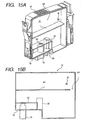
- Fig. 14 is an exploded perspective view of an ink cartridge 10 in a fourth embodiment which is constructed according to the invention.
- a rib 41 is provided, which reinforces mechanical strength of the ink cartridge 10 in its width direction.
- a porous member 20 as described later, has a shape of a rectangular parallelepiped including a slit 51 corresponding to the rib 41 of the container body 12. However, in Fig. 14, the porous member 20 is shown in a deformed state where it is pressure-contacted by a pressure-contacting portion 22 and housed in the container body 12.
- Fig. 15A is a perspective view of the container body 12 of the cartridge 10 in Fig. 14, and Fig. 15B is a front schematic view in which the container body 12 in Fig. 15A is viewed from the direction of an opening surface 28.
- the container body 12 has the rib 41 provided in parallel to an ink supply surface 18.
- the rib 41 is formed integrally with the container body 12 in this embodiment. This rib 41 extends from a side near an ink supply passage 16, that is, a left side in Fig. 15B to a side far from the ink supply passage 16, that is, a right side in Fig. 15B. An end portion of the rib 41 far from the supply passage 16 is not connected to the container body 12 to form a communicating passage 43.
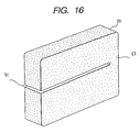
- Fig. 16 is a perspective view of the porous member 20 housed in the space formed by the container body 12 and the lid member 14.
- Theporousmember 20 has a shape of a rectangular parallelepiped that is the approximately same as the shape of the container body 12.
- the porous member 20 further has the slit 51 at its portion corresponding to the rib 41 of the container body 12. One end of this slit 51 is opened, and the other end thereof is not opened but forms a connecting portion 57 that connects a upper half and a lower half of the porous member 20. Since the upper half and the lower half are connected physically by the connecting portion 53, the porous member can be handled as a single member, so that it is easy to handle the porous member in a manufacturing process and the like.
- Fig. 17A is a side view in which the state where the porous member 20 is housed in the container body 12 in the ink cartridge 10 is viewed from the opening surface 28 side of the container body 12. However, for explanation, the lid member 14 is not shown.
- Fig. 17B is a sectional view in which the state in Fig. 17A is viewed from the direction orthogonal to the opening surface 28.
- the porous member 20 of which the outline is approximately a rectangular parallelepiped is compressed at its portion pressure-contacted to the pressure-contacting portion 22, and inserted into the container body 12.
- the capillary power of a portion of the porous member 20 where is near the ink supply passage 16 becomes high by this compression, so that ink collects at this portion. Therefore, the ink can be supplied to the outside without causing a shortage of ink.
- the lid member 14 is joined to the container body 12 so as to seal the opening surface 28.
- an end portion of the rib 41 is also joined to the lid member 14.
- the mechanical reinforcement by the rib 41 becomes stronger.
- the ink cartridge 10 is placed in a pressure reduction room in which pressure is reduced, and the space surrounded by the container body 12 and the lid member 14 is pressure-reduced. Ink is put into the pressure-reduced space surrounded by the container body 14 and the lid member 14, for example, from the ink supply passage 16 thereby to permit the porous member 20 to include the ink. As described above, the ink cartridge 10 is manufactured.
- the mechanical strength of the ink cartridge 10 in the direction of an arrow A in Fig. 17B can be reinforced by the rib 41. Further, since the rib 41 is inserted into the slit 51, the porous member 20 is not compressed around the rib 41, so that it is possible to prevent ink from unnecessarily concentrating in this portion. Further, in the ink cartridge 10, as much ink as possible can be held by the porous member 20 in the space formed by the container body 12 and the lid member 14.
- the rib 41 is provided in parallel to the ink supply surface, the invention is not limited to this. As another example, the rib 41 may be provided perpendicularly to the ink supply surface 18.
- the invention is not limited to this.
- a gap may be provided between the rib 41 and the lid member 14.
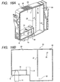
- Fig. 18A is a perspective view of a container body 62 of a cartridge 60 in a fifth embodiment which is constructed according to the invention
- Fig. 18B is a front schematic view in which the container body 62 in Fig. 18A is viewed from the direction of an opening surface 28.
- Parts similar to those of the ink cartridge in the fourth embodiment are denoted by the same reference numerals, and their explanation is omitted.
- a rib 65 is provided perpendicularly to an ink supply surface 18.
- the rib 65 is formed integrally with the container body 62, extends perpendicularly downward from the inside of the upper surface of the container body, and includes a communicating portion 66 between it and the lower surface of the container body 62.
- the width d of the rib 65 is smaller than the inner width w' of the container body 62.
- the inside of the container body 62 is nearly divided into a first room 68 and a second room 69 by this rib 65.
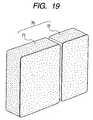
- Fig. 19 is a perspective view of a porous member 70 to be housed into the cartridge 60 in the fifth embodiment.
- This porous member 70 has a first porous member 71 and a second porous member 72 that are two individual members.
- the first porous member 71 has a shape of a rectangular parallelepiped that is the approximately same as the shape of the first room 68 of the container body 62.
- the second porous member 72 has a shape of a rectangular parallelepiped that is the approximately same as the shape of the second room 69 of the container body 62.
- the first porous member 71 and the second porous member 72 that are divided at a portion corresponding to the rib 65 of the container body 62 are combined, whereby the porous member 70 has a shape of a rectangular parallelepiped that is the approximately same as the shape of the container body 62 as a whole.
- the first porous member 71 and the second porous member 72 may be made of the same material or may be made of the different material from each other.
- the first porous member 71 to be inserted into a portion near an ink supply passage 16 uses a material that is high in density and small in diameter of a small pore.
- the second porous member 72 uses a material that is low in density and large in diameter of the small pore.
- first porous member 71 and the second porous member 72 may be made of the same material and may be of the same size to obtain necessary effects. In this case, without increasing the number of kinds of parts, the ink cartridge can be readily manufactured.
- Fig. 20A is a side view in which the state where the porous member 70 is housed in the container body 62 in the ink cartridge 60 is viewed from an opening surface 28 side of the container body 62. However, for explanation, a lid member 14 is not shown.
- Fig. 20B is a sectional view in which the state in Fig. 20A is viewed from the upside.
- the first porous member 71 is inserted into the first room 68
- the second porous member72 is inserted into the second room 69
- the first and second porous members 71 and 72 come into contact with each other at the communicating portion 66.
- the lid member 14 is joined to the opening surface 28 thereby to seal the porous member 70.
- the width d of the rib 65 is smaller than the inner width w' of the container body 62, as shown in Fig. 20B, a gap 74 is formed between the rib 65 and the lid member 14. Therefore, when the lid member 14 is joined to the container body 62, the rib 65 is not joined to the lid member 14. Even if there is the rib 65, the joint portion between the container body 62 and the lid member 14 does not increase. Therefore, the ink cartridge 60 is readily manufactured.
- the rib 65 in the ink cartridge 60, can reinforce the mechanical strength in the direction of an arrow B in Fig. 20B. Further, though there is the gap 74 between the lid 14 and the rib 65 elasticity of the container body 62 or the lid 14 permits first deformation, and at the time of the next deformation, the rib 65 and the lid member 14 come into contact with each other thereby to substantially secure the mechanical strength.
- the porous member 70 is divided at its portion corresponding to the rib 65 into the first porous member 71 and the second porous member 72 that are the individual members. Therefore, around the rib 65, any of the porous members 71 and 72 are not compressed, and it is possible to prevent ink from unnecessarily concentrating on this portion. Further, as much ink as possible can be held by the first and second porous members 71 and 72 in the space formed by the container body 62 and the lid member 14.
- the width of the rib 65 may be made large to join the rib 65 to the lid member 14 similarly.to in the fourth embodiment.
- the slit may be provided for the integral porous member 70 similarly to in the fourth embodiment.
- the rib is formed integrally with the container body, the invention is not limited to this.
- a rib may be joined to a container body, or a gap may be provided between a rib and a container body.
- the invention is not limited to this. Namely, a plurality of ribs may be provided.
Landscapes
- Engineering & Computer Science (AREA)
- Manufacturing & Machinery (AREA)
- Ink Jet (AREA)
- Pens And Brushes (AREA)
Claims (13)
- Tintenpatrone (10), die dazu ausgelegt ist, Tinte zu einer Tintenstrahlaufzeichnungsvorrichtung durch eine Tintenzufuhrnadel der Tintenstrahlaufzeichnungsvorrichtung zuzuführen, umfassend:einen Behälterkörper (12) mit einer Tintenzufuhrfläche (18), an der ein Tintenzufuhrdurchgang (16) vorgesehen ist, in den die Tintenzufuhrnadel eingeführt werden kann, wobei die Höhe (h) seiner Seitenflächen (26, 28) näherungsweise senkrecht zu der Tintenzufuhrfläche (18) größer ist als mindestens eine Breite (w) der Tintenzufuhrfläche (18), und eine der Seitenflächen (28) ist eine Öffnungsfläche, die in der Richtung der Breite (w) offen ist;ein Deckelelement (14), welches die Öffnungsfläche (28) des Behälterkörpers (12) abdichtet; undein poröses Element (20), das in einem durch den Behälterkörper (12) und das Deckelelement (14) gebildeten Raum aufgenommen ist,
dadurch gekennzeichnet, dass die Tintenpatrone (10) ferner einen Presskontaktabschnitt aufweist, der in der Nähe des Tintenzufuhrdurchgangs (16) parallel zu der Tintenzufuhrfläche (18) vorgesehen ist, mit welchem ein Teil des porösen Elements (20) in Presskontakt ist. - Tintenpatrone nach Anspruch 1, bei welcher der Presskontaktabschnitt in der Form eines separaten Elements (22) vorgesehen ist.
- Tintenpatrone nach einem der Ansprüche 1 und 2, bei welcher der Presskontaktabschnitt in seiner Position, welche dem Tintenzufuhrdurchgang entspricht, einen Filter besitzt, durch den Tinte von dem porösen Element passiert.
- Tintenpatrone nach einem der vorhergehenden Ansprüche, ferner umfassend eine Rippe, die innerhalb des durch den Behälterkörper und das Deckelelement gebildeten Raums vorgesehen ist und die Tintenpatrone in ihrer Breitenrichtung verstärkt.
- Tintenpatrone nach Anspruch 4, bei welcher das poröse Element eine Form besitzt, welche die Rippe vermeidet und diese umgibt.
- Tintenpatrone nach Anspruch 4, bei welcher die Rippe integral mit dem Behälterkörper und/oder dem Deckelelement gebildet ist.
- Tintenpatrone nach Anspruch 4, bei welcher die Rippe parallel oder senkrecht zu der Tintenzufuhrfläche vorgesehen ist.
- Tintenpatrone nach Anspruch 4, bei welcher eine Mehrzahl der Rippen vorgesehen ist.
- Tintenpatrone nach Anspruch 5, bei welcher das poröse Element einen Schlitz in einer Position entsprechend der Rippe besitzt.
- Tintenpatrone nach Anspruch 5, bei welcher das poröse Element in mehrere Elemente an einem Abschnitt entsprechend der Rippe aufgeteilt ist.
- Tintenpatrone (10) für eine Tintenstrahlaufzeichnungsvorrichtung nach Anspruch 1, bei welcher das poröse Element (20) derart in dem Raum angeordnet ist, dass es an einem Abschnitt hiervon in der Nähe des Tintenzufuhrdurchgangs (16) stärker komprimiert ist als im Rest hiervon.
- Herstellungsverfahren einer Tintenpatrone zum Zuführen von Tinte zu einer Tintenstrahlaufzeichnungsvorrichtung durch eine Tintenzufuhrnadel der Tintenstrahlaufzeichnungsvorrichtung, umfassend die Schritte:integrales Bilden eines Behälterkörpers mit einer Tintenzufuhrfläche, an der ein Tintenzufuhrdurchgang vorgesehen ist, in den die Tintenzufuhrnadel eingeführt werden kann, wobei die Höhe einer Seitenfläche näherungsweise senkrecht zu der Tintenzufuhrfläche größer ist als mindestens eine Breite der Tintenzufuhrfläche, und eine der Seitenflächen ist eine Öffnungsfläche, die in der Richtung der Breite offen ist;Bilden eines Presskontaktabschnitts in der Nähe des Tintenzufuhrdurchgangs (16) parallel zu der Tintenzufuhrfläche (18);Einführen eines porösen Elements in den Behälterkörper von der Öffnungsfläche; undAbdichten der Öffnungsfläche des Behälterkörpers, in den das poröse Element eingeführt ist, mit einem Deckelelement;
dadurch gekennzeichnet, dass
in dem Einführschritt ein Abschnitt des porösen Elements (20) nahe der Tintenzufuhrfläche (18) von der geneigten Oberseite der Öffnungsfläche (28) zu der Tintenzufuhrfläche (18) gedrückt wird, und danach wird das gesamte poröse Element (20) in den Behälterkörper von der Öffnungsfläche (28) eingeführt, sodass ein Teil des porösen Elements (20) durch den Presskontaktabschnitt in Presskontakt ist. - Herstellungsverfahren nach Anspruch 12, bei welchem in dem Abdichtschritt das Deckelelement an den Behälterkörper vibrationsgeschweißt wird.
Applications Claiming Priority (4)
| Application Number | Priority Date | Filing Date | Title |
|---|---|---|---|
| JP2001285082A JP4462793B2 (ja) | 2001-09-19 | 2001-09-19 | インクカートリッジ |
| JP2001285083 | 2001-09-19 | ||
| JP2001285082 | 2001-09-19 | ||
| JP2001285083A JP2003089221A (ja) | 2001-09-19 | 2001-09-19 | インクカートリッジ |
Publications (2)
| Publication Number | Publication Date |
|---|---|
| EP1295723A1 EP1295723A1 (de) | 2003-03-26 |
| EP1295723B1 true EP1295723B1 (de) | 2006-03-08 |
Family
ID=26622501
Family Applications (1)
| Application Number | Title | Priority Date | Filing Date |
|---|---|---|---|
| EP02021260A Expired - Lifetime EP1295723B1 (de) | 2001-09-19 | 2002-09-19 | Tintenpatrone und Verfahren zu ihrer Herstellung |
Country Status (10)
| Country | Link |
|---|---|
| US (2) | US6796642B2 (de) |
| EP (1) | EP1295723B1 (de) |
| KR (2) | KR100572780B1 (de) |
| CN (2) | CN1250399C (de) |
| AT (1) | ATE319573T1 (de) |
| CA (1) | CA2404186C (de) |
| DE (1) | DE60209605T2 (de) |
| ES (1) | ES2259688T3 (de) |
| SG (2) | SG104981A1 (de) |
| TW (1) | TW558512B (de) |
Families Citing this family (23)
| Publication number | Priority date | Publication date | Assignee | Title |
|---|---|---|---|---|
| EP1295723B1 (de) * | 2001-09-19 | 2006-03-08 | Seiko Epson Corporation | Tintenpatrone und Verfahren zu ihrer Herstellung |
| US7168801B2 (en) * | 2003-01-28 | 2007-01-30 | Samsung Electronics Co., Ltd. | Ink cartridge |
| JP2004338383A (ja) * | 2003-04-25 | 2004-12-02 | Canon Inc | インクカートリッジ、該インクカートリッジを搭載する記録装置および該インクタンクの製造方法 |
| JP4277276B2 (ja) * | 2004-01-30 | 2009-06-10 | セイコーエプソン株式会社 | 液体容器 |
| US7338903B2 (en) * | 2004-04-24 | 2008-03-04 | Taiwan Semiconductor Manufacturing Co., Ltd. | Sequential reducing plasma and inert plasma pre-treatment method for oxidizable conductor layer |
| US7828421B2 (en) | 2005-09-29 | 2010-11-09 | Brother Kogyo Kabushiki Kaisha | Ink cartridge arrangements |
| US8025376B2 (en) | 2005-09-29 | 2011-09-27 | Brother Kogyo Kabushiki Kaisha | Ink cartridges |
| US7837311B2 (en) | 2005-09-29 | 2010-11-23 | Brother Kogyo Kabushiki Kaisha | Ink cartridges |
| US7810916B2 (en) | 2005-09-29 | 2010-10-12 | Brother Kogyo Kabushiki Kaisha | Ink cartridges |
| US7682004B2 (en) | 2005-09-29 | 2010-03-23 | Brother Kogyo Kabushiki Kaisha | Ink cartridges |
| US7775645B2 (en) | 2005-09-29 | 2010-08-17 | Brother Kogyo Kabushiki Kaisha | Methods of forming cartridges, such as ink cartridges |
| US7553007B2 (en) | 2005-09-29 | 2009-06-30 | Brother Kogyo Kabushiki Kaisha | Ink cartridges |
| CN100439108C (zh) * | 2005-11-11 | 2008-12-03 | 李祥海 | 一种墨盒及制作方法 |
| US20080055371A1 (en) * | 2006-06-29 | 2008-03-06 | Charles Stanley Aldrich | Ink Tank Interface for an Imaging Apparatus |
| USD580971S1 (en) | 2006-09-08 | 2008-11-18 | Kenneth Yuen | Ink cartridge |
| US20080165214A1 (en) * | 2007-01-05 | 2008-07-10 | Kenneth Yuen | Ink cartridge fluid flow arrangements and methods |
| US20080204528A1 (en) * | 2007-02-28 | 2008-08-28 | Kenneth Yuen | Ink cartridge |
| JP2010036457A (ja) * | 2008-08-05 | 2010-02-18 | Seiko Epson Corp | 液体容器、包装された液体容器及びその製造方法 |
| JP5780785B2 (ja) * | 2011-03-11 | 2015-09-16 | キヤノン株式会社 | 負圧発生部材の挿入方法および負圧発生部材挿入装置 |
| US9487011B2 (en) * | 2014-06-11 | 2016-11-08 | Inkcycle, Inc. | Latch improvement for a printer supply |
| JP2017081083A (ja) * | 2015-10-30 | 2017-05-18 | キヤノン株式会社 | 液体吐出装置、ヘッド及び液体充填方法 |
| WO2017182806A1 (en) * | 2016-04-20 | 2017-10-26 | Videojet Technologies Inc. | Cartridge and printer |
| US11225084B2 (en) | 2019-03-29 | 2022-01-18 | Brother Kogyo Kabushiki Kaisha | Replenishable liquid storage tank including backpressure application member, and image-forming apparatus provided with the same |
Family Cites Families (30)
| Publication number | Priority date | Publication date | Assignee | Title |
|---|---|---|---|---|
| JP3327046B2 (ja) | 1995-04-21 | 2002-09-24 | セイコーエプソン株式会社 | 記録装置用インクタンクならびにインクタンクのインク補給方法 |
| JP2817657B2 (ja) | 1994-08-23 | 1998-10-30 | 富士ゼロックス株式会社 | インク供給装置および記録装置 |
| US5182581A (en) * | 1988-07-26 | 1993-01-26 | Canon Kabushiki Kaisha | Ink jet recording unit having an ink tank section containing porous material and a recording head section |
| JP2675877B2 (ja) | 1989-10-22 | 1997-11-12 | キヤノン株式会社 | インクジェットヘッドカートリッジ及び該カートリッジを搭載したインクジェット記録装置 |
| JP2675876B2 (ja) | 1989-10-22 | 1997-11-12 | キヤノン株式会社 | インクジェットヘッドカートリッジ及び該カートリッジを搭載したインクジェット記録装置 |
| US5488401A (en) * | 1991-01-18 | 1996-01-30 | Seiko Epson Corporation | Ink-jet recording apparatus and ink tank cartridge thereof |
| JPH05162324A (ja) | 1991-12-11 | 1993-06-29 | Canon Inc | インクジェット記録装置 |
| JP2683187B2 (ja) | 1992-07-24 | 1997-11-26 | キヤノン株式会社 | 液体収納容器 |
| US5754207A (en) * | 1992-08-12 | 1998-05-19 | Hewlett-Packard Company | Volume indicating ink reservoir cartridge system |
| US5448275A (en) * | 1992-12-18 | 1995-09-05 | Hewlett-Packard Company | Thermal ink jet pen having foam controlled backpressure regulation and method of manufacture and operation |
| JPH0725024A (ja) | 1993-07-09 | 1995-01-27 | Canon Inc | インクカートリッジおよびこれを用いたインクジェット記録装置 |
| JPH0760978A (ja) | 1993-08-23 | 1995-03-07 | Canon Inc | 交換型インクジェット用インクカートリッジ |
| US5949461A (en) * | 1994-02-18 | 1999-09-07 | Nu-Kote Imaging International, Inc. | Ink refill bottle |
| DE9405723U1 (de) * | 1994-04-06 | 1994-06-01 | Pelikan Produktions Ag, Egg | Tintenpatrone für einen Druckkopf eines Ink-Jet-Printers |
| JP3113512B2 (ja) | 1994-07-28 | 2000-12-04 | シャープ株式会社 | インクジェット記録装置 |
| EP0709209B1 (de) * | 1994-10-31 | 1998-12-30 | Hewlett-Packard Company | Tintenbehälter mit Schutzblatt für porösen Körper |
| DE69508519T2 (de) | 1994-10-31 | 1999-07-08 | Hewlett-Packard Co., Palo Alto, Calif. | Tintenstrahlschreiber mit einem Kapillaritätsgradient |
| JPH08132638A (ja) | 1994-11-07 | 1996-05-28 | Fuji Xerox Co Ltd | インクタンク |
| DE69526302T2 (de) | 1994-11-07 | 2002-11-14 | Canon Aptex Inc., Mitsukaido | Drucker mit zugehöriger Tintenkassette |
| US5671001A (en) * | 1995-03-03 | 1997-09-23 | Hewlett-Packard Company | Leak resistant ink containment for a printer |
| US6168266B1 (en) | 1995-09-29 | 2001-01-02 | Canon Kabushiki Kaisha | Ink tank cartridge, a manufacturing method thereof and a packaging structure of the ink tank cartridge |
| JP3160509B2 (ja) | 1995-09-29 | 2001-04-25 | キヤノン株式会社 | インクジェット用インクカートリッジおよびその製造方法 |
| DE69733176T2 (de) * | 1996-02-21 | 2006-02-16 | Seiko Epson Corp. | Tintenkartusche |
| JP3251881B2 (ja) | 1996-08-02 | 2002-01-28 | キヤノン株式会社 | 液体収納容器及び該液体収納容器を備えるインクジェットカートリッジ及び該インクジェットカートリッジを備えるインクジェット記録装置 |
| JPH10250104A (ja) | 1997-03-12 | 1998-09-22 | Seiko Epson Corp | インクジェット式記録装置用インクカートリッジ、及びその製造方法 |
| JPH10278288A (ja) | 1997-04-01 | 1998-10-20 | Ricoh Co Ltd | インクタンク及びその製造方法 |
| ATE267707T1 (de) * | 1999-03-29 | 2004-06-15 | Seiko Epson Corp | Verfahren und vorrichtung zum befüülen von tintenpatronen mit tinte |
| JP2000351218A (ja) | 1999-06-11 | 2000-12-19 | Hitachi Koki Co Ltd | インクボトル |
| JP2001113717A (ja) | 1999-10-19 | 2001-04-24 | Canon Inc | インクジェット記録用インクタンク及びインクジェット記録用インクカートリッジの製造方法 |
| EP1295723B1 (de) * | 2001-09-19 | 2006-03-08 | Seiko Epson Corporation | Tintenpatrone und Verfahren zu ihrer Herstellung |
-
2002
- 2002-09-19 EP EP02021260A patent/EP1295723B1/de not_active Expired - Lifetime
- 2002-09-19 SG SG200205670A patent/SG104981A1/en unknown
- 2002-09-19 CN CNB021424608A patent/CN1250399C/zh not_active Expired - Fee Related
- 2002-09-19 SG SG200506676-6A patent/SG131786A1/en unknown
- 2002-09-19 CA CA002404186A patent/CA2404186C/en not_active Expired - Fee Related
- 2002-09-19 ES ES02021260T patent/ES2259688T3/es not_active Expired - Lifetime
- 2002-09-19 TW TW091121696A patent/TW558512B/zh active
- 2002-09-19 KR KR1020020057164A patent/KR100572780B1/ko not_active Expired - Fee Related
- 2002-09-19 AT AT02021260T patent/ATE319573T1/de not_active IP Right Cessation
- 2002-09-19 CN CN02254638U patent/CN2571588Y/zh not_active Expired - Fee Related
- 2002-09-19 DE DE60209605T patent/DE60209605T2/de not_active Expired - Lifetime
- 2002-09-19 US US10/246,757 patent/US6796642B2/en not_active Expired - Fee Related
-
2004
- 2004-08-31 US US10/929,581 patent/US6986569B2/en not_active Expired - Fee Related
-
2005
- 2005-09-15 KR KR1020050086313A patent/KR100626917B1/ko not_active Expired - Fee Related
Also Published As
| Publication number | Publication date |
|---|---|
| DE60209605D1 (de) | 2006-05-04 |
| CN1405001A (zh) | 2003-03-26 |
| KR100572780B1 (ko) | 2006-04-19 |
| US6796642B2 (en) | 2004-09-28 |
| TW558512B (en) | 2003-10-21 |
| HK1055097A1 (en) | 2003-12-24 |
| CN1250399C (zh) | 2006-04-12 |
| US20030071881A1 (en) | 2003-04-17 |
| SG131786A1 (en) | 2007-05-28 |
| US6986569B2 (en) | 2006-01-17 |
| KR20030025210A (ko) | 2003-03-28 |
| CA2404186A1 (en) | 2003-03-19 |
| ES2259688T3 (es) | 2006-10-16 |
| KR20050099478A (ko) | 2005-10-13 |
| DE60209605T2 (de) | 2007-01-04 |
| CN2571588Y (zh) | 2003-09-10 |
| CA2404186C (en) | 2006-07-04 |
| SG104981A1 (en) | 2004-07-30 |
| ATE319573T1 (de) | 2006-03-15 |
| EP1295723A1 (de) | 2003-03-26 |
| US20050030356A1 (en) | 2005-02-10 |
| KR100626917B1 (ko) | 2006-09-20 |
Similar Documents
| Publication | Publication Date | Title |
|---|---|---|
| EP1295723B1 (de) | Tintenpatrone und Verfahren zu ihrer Herstellung | |
| EP0794058B1 (de) | Ventilteil, Ventil, Tintenbehälter und Tintenstrahlkartusche mit diesem Behälter | |
| KR100389444B1 (ko) | 기록 장치용 잉크 카트리지 | |
| EP0838340A2 (de) | Tintenstrahlpatrone, tintenkopf und drucher | |
| US20030016279A1 (en) | Ink tank | |
| EP0730966B1 (de) | Tintenbehälter und Herstellungsverfahren dafür | |
| US6536888B2 (en) | Ink cartridge with internal ink bag and method of filling | |
| EP1219445A1 (de) | Tintenpatrone | |
| HK1055097B (en) | Ink cartridge and its manufacturing method | |
| US8147048B2 (en) | Ink jet recording cartridge | |
| JP2007015272A (ja) | 記録ヘッドおよびこれに使用するシール部材 | |
| CN100506542C (zh) | 墨盒及其制造方法 | |
| JP2003089221A (ja) | インクカートリッジ | |
| CN111806094B (zh) | 墨水容器 | |
| JP3201053B2 (ja) | インクジェットカートリッジ | |
| JP3379174B2 (ja) | インク収納容器及びその製造方法 | |
| US20250115051A1 (en) | Ink cartridge and printing apparatus | |
| JPH10315497A (ja) | インクカートリッジ | |
| JPH0679545U (ja) | インクカートリッジ構成 | |
| CN115458859A (zh) | 电池模组和电子设备 | |
| JP2001026118A (ja) | インクカートリッジ | |
| JPH0858106A (ja) | インク容器の製造方法 | |
| JPH07101072A (ja) | 液体貯蔵容器 |
Legal Events
| Date | Code | Title | Description |
|---|---|---|---|
| PUAI | Public reference made under article 153(3) epc to a published international application that has entered the european phase |
Free format text: ORIGINAL CODE: 0009012 |
|
| 17P | Request for examination filed |
Effective date: 20030124 |
|
| AK | Designated contracting states |
Kind code of ref document: A1 Designated state(s): AT BE BG CH CY CZ DE DK EE ES FI FR GB GR IE IT LI LU MC NL PT SE SK TR |
|
| AX | Request for extension of the european patent |
Extension state: AL LT LV MK RO SI |
|
| 17Q | First examination report despatched |
Effective date: 20030611 |
|
| AKX | Designation fees paid |
Designated state(s): AT BE BG CH CY CZ DE DK EE ES FI FR GB GR IE IT LI LU MC NL PT SE SK TR |
|
| GRAP | Despatch of communication of intention to grant a patent |
Free format text: ORIGINAL CODE: EPIDOSNIGR1 |
|
| GRAS | Grant fee paid |
Free format text: ORIGINAL CODE: EPIDOSNIGR3 |
|
| GRAA | (expected) grant |
Free format text: ORIGINAL CODE: 0009210 |
|
| AK | Designated contracting states |
Kind code of ref document: B1 Designated state(s): AT BE BG CH CY CZ DE DK EE ES FI FR GB GR IE IT LI LU MC NL PT SE SK TR |
|
| PG25 | Lapsed in a contracting state [announced via postgrant information from national office to epo] |
Ref country code: AT Free format text: LAPSE BECAUSE OF FAILURE TO SUBMIT A TRANSLATION OF THE DESCRIPTION OR TO PAY THE FEE WITHIN THE PRESCRIBED TIME-LIMIT Effective date: 20060308 Ref country code: SK Free format text: LAPSE BECAUSE OF FAILURE TO SUBMIT A TRANSLATION OF THE DESCRIPTION OR TO PAY THE FEE WITHIN THE PRESCRIBED TIME-LIMIT Effective date: 20060308 Ref country code: FI Free format text: LAPSE BECAUSE OF FAILURE TO SUBMIT A TRANSLATION OF THE DESCRIPTION OR TO PAY THE FEE WITHIN THE PRESCRIBED TIME-LIMIT Effective date: 20060308 Ref country code: BE Free format text: LAPSE BECAUSE OF FAILURE TO SUBMIT A TRANSLATION OF THE DESCRIPTION OR TO PAY THE FEE WITHIN THE PRESCRIBED TIME-LIMIT Effective date: 20060308 |
|
| REG | Reference to a national code |
Ref country code: GB Ref legal event code: FG4D |
|
| REG | Reference to a national code |
Ref country code: CH Ref legal event code: EP |
|
| REG | Reference to a national code |
Ref country code: IE Ref legal event code: FG4D |
|
| REF | Corresponds to: |
Ref document number: 60209605 Country of ref document: DE Date of ref document: 20060504 Kind code of ref document: P |
|
| REG | Reference to a national code |
Ref country code: SE Ref legal event code: TRGR |
|
| PG25 | Lapsed in a contracting state [announced via postgrant information from national office to epo] |
Ref country code: BG Free format text: LAPSE BECAUSE OF FAILURE TO SUBMIT A TRANSLATION OF THE DESCRIPTION OR TO PAY THE FEE WITHIN THE PRESCRIBED TIME-LIMIT Effective date: 20060608 Ref country code: DK Free format text: LAPSE BECAUSE OF FAILURE TO SUBMIT A TRANSLATION OF THE DESCRIPTION OR TO PAY THE FEE WITHIN THE PRESCRIBED TIME-LIMIT Effective date: 20060608 |
|
| REG | Reference to a national code |
Ref country code: CH Ref legal event code: NV Representative=s name: BOVARD AG PATENTANWAELTE |
|
| PG25 | Lapsed in a contracting state [announced via postgrant information from national office to epo] |
Ref country code: PT Free format text: LAPSE BECAUSE OF FAILURE TO SUBMIT A TRANSLATION OF THE DESCRIPTION OR TO PAY THE FEE WITHIN THE PRESCRIBED TIME-LIMIT Effective date: 20060808 |
|
| REG | Reference to a national code |
Ref country code: HK Ref legal event code: GR Ref document number: 1055097 Country of ref document: HK |
|
| PG25 | Lapsed in a contracting state [announced via postgrant information from national office to epo] |
Ref country code: IE Free format text: LAPSE BECAUSE OF NON-PAYMENT OF DUE FEES Effective date: 20060919 |
|
| PG25 | Lapsed in a contracting state [announced via postgrant information from national office to epo] |
Ref country code: MC Free format text: LAPSE BECAUSE OF NON-PAYMENT OF DUE FEES Effective date: 20060930 |
|
| REG | Reference to a national code |
Ref country code: ES Ref legal event code: FG2A Ref document number: 2259688 Country of ref document: ES Kind code of ref document: T3 |
|
| ET | Fr: translation filed | ||
| PLBE | No opposition filed within time limit |
Free format text: ORIGINAL CODE: 0009261 |
|
| STAA | Information on the status of an ep patent application or granted ep patent |
Free format text: STATUS: NO OPPOSITION FILED WITHIN TIME LIMIT |
|
| 26N | No opposition filed |
Effective date: 20061211 |
|
| PG25 | Lapsed in a contracting state [announced via postgrant information from national office to epo] |
Ref country code: GR Free format text: LAPSE BECAUSE OF FAILURE TO SUBMIT A TRANSLATION OF THE DESCRIPTION OR TO PAY THE FEE WITHIN THE PRESCRIBED TIME-LIMIT Effective date: 20060609 Ref country code: CZ Free format text: LAPSE BECAUSE OF FAILURE TO SUBMIT A TRANSLATION OF THE DESCRIPTION OR TO PAY THE FEE WITHIN THE PRESCRIBED TIME-LIMIT Effective date: 20060308 |
|
| PG25 | Lapsed in a contracting state [announced via postgrant information from national office to epo] |
Ref country code: EE Free format text: LAPSE BECAUSE OF FAILURE TO SUBMIT A TRANSLATION OF THE DESCRIPTION OR TO PAY THE FEE WITHIN THE PRESCRIBED TIME-LIMIT Effective date: 20060308 |
|
| PG25 | Lapsed in a contracting state [announced via postgrant information from national office to epo] |
Ref country code: LU Free format text: LAPSE BECAUSE OF NON-PAYMENT OF DUE FEES Effective date: 20060919 Ref country code: TR Free format text: LAPSE BECAUSE OF FAILURE TO SUBMIT A TRANSLATION OF THE DESCRIPTION OR TO PAY THE FEE WITHIN THE PRESCRIBED TIME-LIMIT Effective date: 20060308 |
|
| PG25 | Lapsed in a contracting state [announced via postgrant information from national office to epo] |
Ref country code: CY Free format text: LAPSE BECAUSE OF FAILURE TO SUBMIT A TRANSLATION OF THE DESCRIPTION OR TO PAY THE FEE WITHIN THE PRESCRIBED TIME-LIMIT Effective date: 20060308 |
|
| PGFP | Annual fee paid to national office [announced via postgrant information from national office to epo] |
Ref country code: CH Payment date: 20100914 Year of fee payment: 9 Ref country code: ES Payment date: 20100923 Year of fee payment: 9 |
|
| PGFP | Annual fee paid to national office [announced via postgrant information from national office to epo] |
Ref country code: FR Payment date: 20100921 Year of fee payment: 9 Ref country code: IT Payment date: 20100922 Year of fee payment: 9 Ref country code: SE Payment date: 20100913 Year of fee payment: 9 |
|
| PGFP | Annual fee paid to national office [announced via postgrant information from national office to epo] |
Ref country code: GB Payment date: 20100916 Year of fee payment: 9 |
|
| PGFP | Annual fee paid to national office [announced via postgrant information from national office to epo] |
Ref country code: NL Payment date: 20100916 Year of fee payment: 9 |
|
| PGFP | Annual fee paid to national office [announced via postgrant information from national office to epo] |
Ref country code: DE Payment date: 20100915 Year of fee payment: 9 |
|
| REG | Reference to a national code |
Ref country code: CH Ref legal event code: PFA Owner name: SEIKO EPSON CORPORATION Free format text: SEIKO EPSON CORPORATION#4-1, NISHI-SHINJUKU 2-CHOME#SHINJUKU-KU, TOKYO 163-0811 (JP) -TRANSFER TO- SEIKO EPSON CORPORATION#4-1, NISHI-SHINJUKU 2-CHOME#SHINJUKU-KU, TOKYO 163-0811 (JP) |
|
| REG | Reference to a national code |
Ref country code: NL Ref legal event code: V1 Effective date: 20120401 |
|
| REG | Reference to a national code |
Ref country code: CH Ref legal event code: PL |
|
| GBPC | Gb: european patent ceased through non-payment of renewal fee |
Effective date: 20110919 |
|
| PG25 | Lapsed in a contracting state [announced via postgrant information from national office to epo] |
Ref country code: IT Free format text: LAPSE BECAUSE OF NON-PAYMENT OF DUE FEES Effective date: 20110919 |
|
| REG | Reference to a national code |
Ref country code: FR Ref legal event code: ST Effective date: 20120531 |
|
| REG | Reference to a national code |
Ref country code: SE Ref legal event code: EUG |
|
| REG | Reference to a national code |
Ref country code: DE Ref legal event code: R119 Ref document number: 60209605 Country of ref document: DE Effective date: 20120403 |
|
| PG25 | Lapsed in a contracting state [announced via postgrant information from national office to epo] |
Ref country code: LI Free format text: LAPSE BECAUSE OF NON-PAYMENT OF DUE FEES Effective date: 20110930 Ref country code: NL Free format text: LAPSE BECAUSE OF NON-PAYMENT OF DUE FEES Effective date: 20120401 Ref country code: CH Free format text: LAPSE BECAUSE OF NON-PAYMENT OF DUE FEES Effective date: 20110930 Ref country code: DE Free format text: LAPSE BECAUSE OF NON-PAYMENT OF DUE FEES Effective date: 20120403 |
|
| PG25 | Lapsed in a contracting state [announced via postgrant information from national office to epo] |
Ref country code: GB Free format text: LAPSE BECAUSE OF NON-PAYMENT OF DUE FEES Effective date: 20110919 Ref country code: FR Free format text: LAPSE BECAUSE OF NON-PAYMENT OF DUE FEES Effective date: 20110930 |
|
| PG25 | Lapsed in a contracting state [announced via postgrant information from national office to epo] |
Ref country code: SE Free format text: LAPSE BECAUSE OF NON-PAYMENT OF DUE FEES Effective date: 20110920 |
|
| REG | Reference to a national code |
Ref country code: ES Ref legal event code: FD2A Effective date: 20130605 |
|
| PG25 | Lapsed in a contracting state [announced via postgrant information from national office to epo] |
Ref country code: ES Free format text: LAPSE BECAUSE OF NON-PAYMENT OF DUE FEES Effective date: 20110920 |