EP1289269A2 - Système d'impression, procédé d'impression, et programme de commande pour le système d'impression - Google Patents
Système d'impression, procédé d'impression, et programme de commande pour le système d'impression Download PDFInfo
- Publication number
- EP1289269A2 EP1289269A2 EP02017614A EP02017614A EP1289269A2 EP 1289269 A2 EP1289269 A2 EP 1289269A2 EP 02017614 A EP02017614 A EP 02017614A EP 02017614 A EP02017614 A EP 02017614A EP 1289269 A2 EP1289269 A2 EP 1289269A2
- Authority
- EP
- European Patent Office
- Prior art keywords
- color
- printing
- saturation
- color ink
- ink
- Prior art date
- Legal status (The legal status is an assumption and is not a legal conclusion. Google has not performed a legal analysis and makes no representation as to the accuracy of the status listed.)
- Granted
Links
Images


Classifications
-
- H—ELECTRICITY
- H04—ELECTRIC COMMUNICATION TECHNIQUE
- H04N—PICTORIAL COMMUNICATION, e.g. TELEVISION
- H04N1/00—Scanning, transmission or reproduction of documents or the like, e.g. facsimile transmission; Details thereof
- H04N1/40—Picture signal circuits
- H04N1/40012—Conversion of colour to monochrome
-
- H—ELECTRICITY
- H04—ELECTRIC COMMUNICATION TECHNIQUE
- H04N—PICTORIAL COMMUNICATION, e.g. TELEVISION
- H04N1/00—Scanning, transmission or reproduction of documents or the like, e.g. facsimile transmission; Details thereof
- H04N1/46—Colour picture communication systems
- H04N1/56—Processing of colour picture signals
- H04N1/60—Colour correction or control
- H04N1/6058—Reduction of colour to a range of reproducible colours, e.g. to ink- reproducible colour gamut
Definitions
- the present invention relates to a printing system, a printing method, a control program for the printing system, and a medium which stores the control program for the printing system.
- chromatic color inks as a cyan color ink, a magenta color ink, and a yellow color ink, in addition to a black color ink.
- a black color ink usually contains carbon black, and the darkness of a black color ink depends on the quantity of the carbon black contained.
- a plurality of black color ink with different darkness are used, and the term of a black color ink is sometimes used as a general term for several black color inks with different darkness.
- a cyan color ink for adjusting the color tone using chromatic color inks minutely, there are separately provided a cyan color ink, a magenta color ink and a yellow color ink, which are low in saturation, and printing of a monochromatic image is conducted using those inks.
- the present invention has been accomplished in view of the above-mentioned problems and it is an object of the invention to provide a printing system and printing method capable of ensuring a sufficient selection range of saturation and printing a monochromatic image of a high image quality having a sufficient power of expression, as well as a control program for the printing system.
- the present invention adopts a construction wherein, in a predetermined print head, the gradation characteristic of a color region capable of being color-reproduced is enhanced while narrowing the color region with use of a cyan color ink of a low saturation, a magenta color ink of a low saturation, a yellow color ink of a high saturation, and a black color ink, and color reproduction is performed.
- the color-reproducible color region is narrowed substantially in the directions of cyan and magenta by the cyan and magenta color inks low in saturation.
- the color tone of the monochromatic image printed can be adjusted minutely because the gradation characteristic is enhanced as to cyan and magenta color components.
- the color-reproducible color region is wide substantially in the direction of yellow.
- the human eyes sense the yellow component as a relatively small component in comparison with cyan and magenta components, so even if there is used a yellow color ink of a high saturation, it is possible to develop a color tone of a fine texture in appearance. That is, while developing a color tone of a fine texture in appearance, it is possible to ensure a sufficient selection range of saturation of the printed monochromatic image and obtain a sufficient power of expression.
- the foregoing yellow color ink of a high saturation may be constituted by an ink of a high saturation and a high density
- the foregoing cyan color ink of a low saturation may be constituted by an ink low in both saturation and density
- the foregoing magenta color ink may be constituted by an ink low in both saturation and density. That is, the color-reproducible color region is narrowed substantially in the directions of cyan and magenta by the cyan and magenta inks low in both saturation and density. Substantially in the direction of yellow the same color region is widened by the yellow color ink high in both saturation and density. Consequently, with these color inks, it is possible to ensure a sufficient selection range of saturation of a monochromatic image printed and obtain a sufficient power of expression while developing a color tone of a fine texture in appearance.
- this can provide examples of various color inks.
- Black color ink are included not only black color ink with hue not imparted thereto but also black color ink with hue imparted thereto.
- cyan color ink are included mixtures of a cyan color ink as a main component with other kinds of color inks. This is also true of magenta and yellow color inks.
- the printing system according to the present invention may be composed of a printer and a computer connected to the printer, or may be constituted by a printer alone. Various system configurations can be adopted.
- a printing system that can effect both monochromatic image printing and color printing
- a construction wherein, in color printing, color reproduction is performed using a cyan color ink high in both saturation and density and a magenta color ink high in both saturation and density together with the aforesaid various color inks, while in monochromatic image printing, such cyan and magenta color inks high in both saturation and density are not used.
- cyan and magenta color inks high in both saturation and density are not used.
- a color twist phenomenon such that with a color ink high in both saturation and density there is developed an unintended hue because of a low dot density.
- such a color twist phenomenon does not occur because cyan and magenta color inks high in both saturation and density are not used in monochromatic image printing.
- color conversion tables for conversion from printing data to data for driving a print head may be provided correspondingly to printing types and may be switched from one to another according to the type of printing.
- an example of construction of the Black color ink comprises plural Black color inks different in density, and printing may be conducted using any or a combination of such Black color inks. That is, not only an appropriate Black color ink can be selected according to the brightness of image but also it is possible to diminish the gap in brightness at the time of replacing various chromatic color inks with Black color inks.
- the above Black color inks are a black color ink and a light black color ink lower in density than the black color ink.
- the light blank color ink may be provided so that it can be replaced with one or both of cyan and magenta color inks high in both saturation and density. That is, even if the number of ink cartridges which can be loaded to the printing system is limited, both printing of a monochromatic image of a high quality and color printing can be done in one and same printing system.
- a ratio setting acquiring means for acquiring the setting of a ratio between such plural Black color inks as referred to above and other color inks and printing is performed in accordance with the setting of the ratio acquired. If there are used many chromatic color inks, the running cost is apt to increase although the image quality will be improved.
- the ratio setting acquiring means it is possible to set the ratio between plural Black color inks and other color inks, with the result that it becomes possible to select according to preference whether the printing to be performed is a printing with importance attached to image quality or is a printing with importance attached to running cost.
- a print type acquiring means for acquiring a print type out of a monochromatic image printing type and a color printing type, and printing is performed in accordance with the print type acquired.
- the print type acquiring means it is possible to set whether the printing to be performed is monochromatic image printing or color printing, whereby the convenience is improved. It is optional whether the print type acquiring means should use an operation input or an application program to acquire a print type.
- the gradation characteristic in the said color region is enhanced and printing of a monochromatic image of a high image quality is performed.
- a printing system wherein, in printing a monochromatic image, there are used an achromatic color ink and a chromatic color ink of a low saturation which narrows a printable color region to a lower saturation side than in color printing, thereby effecting color reproduction in a narrower color region than in color printing.
- a yellow color ink high in saturation is used together with the above achromatic color ink and chromatic color ink of a low saturation, and printing of a monochromatic image is performed without narrowing the above color region from the time of color printing substantially in the direction of yellow.
- the color region is not narrowed from the time of color printing substantially in the direction of yellow, but is narrowed from the time of color printing substantially in the other directions than the direction of yellow.
- the color-reproducible color region becomes wide substantially in the direction of yellow.
- the human eyes sense yellow component relatively lower than cyan and magenta components, so even if there is used a yellow color ink of a high saturation at the time of printing a monochromatic image, it is possible to develop a color tone of a fine texture in appearance.
- the achromatic color ink may be a black or gray color ink or may be even a black color ink with hue imparted thereto.
- the chromatic color ink of a low saturation may be a light cyan color ink, a light magenta color ink, or a color ink intermediate between light cyan and light magenta.
- the object of application of the technique which enhances the gradation characteristic in a color-reproducible region while narrowing the same region and which performs color reproduction in this state is not always limited to a substantial system, but it is a matter of course that a predetermined processing procedure for the color reproduction underlies the invention.
- the present invention is also applicable as a method and it goes without saying that the above system configuration can be made corresponding to the method.
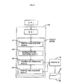
- Fig. 1 illustrates a schematic construction of a printing system 100 according to an embodiment of the present invention.
- a block configuration of a person computer (PC) 10 is also shown in the same figure.
- the printing system 100 of this embodiment comprises a personal computer 10 and a printer 20 which can make color printing. Therefore, the printing system 100 can perform not only printing of a monochromatic image but also color printing.
- the monochromatic image means an image having a substantially unitary hue. It is not limited to an image printed using a single color ink, but it can be printed using plural kinds of color inks at approximate equal proportions.
- the personal computer 10 is provided with a CPU 11 which serves as the nucleus in arithmetic processing.
- the CPU 11 controls the whole of the personal computer 10 through a system bus 10a.
- ROM 12, RAM 13, hard disc drive 14, CD-ROM drive 15, input interface (input I/F) 16, CRT interface (CRT I/F) 17, communication interface (communication I/F) 18, and printer interface (printer I/F) 19 are connected to the system bus 10a.
- the personal computer 10 used in this embodiment is what is called a desk top type personal computer and is described in a simplified state of its configuration.
- a computer having a general computer configuration is employable as the personal computer 10.
- a notebook type or a mobile computer will do.
- the computer applicable to the printing system of the present invention is not limited to the personal computer.
- a hard disc 14a connected to the hard disc drive 14 there are stored an operating system (OS) as software and application programs (APL) which can generate document information and image information.
- OS operating system
- APL application programs
- a keyboard 16a and a mouse 16b are connected to the input I/F 16 as operating input devices and also connected are a scanner and a digital camera (neither shown). Therefore, it is possible to read an image from the scanner or the digital camera and effect printing of a monochromatic image.
- a display 17a is connected to the CRT I/F 17. Further, the printer 20 is connected to the printer I/F 19 through a parallel interface cable. Of course, it is not always necessary that the interface for connection with the printer 20 be limited to the parallel interface. Various connection modes may be adopted, including serial interface, SCSI, and USB connections. Any other connection modes to be developed in future are also employable.
- the recording medium which can store the softwares is not limited to the hard disc.
- it may be a CD-ROM or a flexible disc.
- the softwares stored in any of these recording mediums are read through the CD-ROM drive 15 or a flexible disc drive (not shown) and are installed in the hard disc 14a, then are read onto the RAM 13 by CPU 11, which in turn executes various processings.
- the recording medium no limitation is made to those referred to above, but there may be used a magnetooptic disc or a non-volatile memory as a semiconductor device.
- the communication I/F 18 such as a modem connected to the system bus 10a may be connected to the Internet and access may be made to a server capable of storing various programs, allowing softwares to be down-loaded.
- the printer 20 used in this embodiment is an ink jet printer and employs a total of six color inks in color printing, which are a cyan color ink (C) high in both saturation and density, a magenta color ink (M) high in both saturation and density, a yellow color ink (Y) high in both saturation and density, a cyan color ink (c) low in both saturation and density and called light cyan, a magenta color ink (m) low in both saturation and density and called light magenta, and a black color ink (k) which is one of a black color ink in general meaning.
- k1, k2 two kinds of light black color inks (k1, k2), which are also one of a black color ink in general meaning, and they are low in density, are used instead of high-density cyan and magenta.
- the colors of inks will be described merely as C, M, Y, c, m, K, k1, and k2.
- the color inks C, M, Y, c, and m are chromatic color inks, while the color inks K, k1, and k2 are achromatic inks.
- k1 is higher in brightness than K
- k2 is still higher in brightness than k1.
- Fig. 2 shows a block construction of the printer 20 together with the personal computer 10.
- a bus 20a is provided in the interior of the printer 20, and CPU 21, ROM 22, RAM 23, ASIC 24, control IC 25, communication I/O 26, and interface (I/F) 27 for the transmission of image data and drive signals, are connected to the bus 20a.
- the CPU 21 controls various portions in accordance with programs stored in the ROM 22 while utilizing RAM 23 as a work area.
- ASIC 24 is an IC customized for driving a print head (not shown) and it performs processings for driving the print head while transmitting and receiving predetermined signals to and from the CPU 21. Further, the ASIC 24 outputs applied voltage data for a head driver 29.
- the head driver 29 is a circuit which comprises a dedicated IC, a driving transistor, and a heat sink. In accordance with the applied voltage data inputted from ASIC 24 the head driver 29 generates an applied voltage pattern for piezoelectric elements incorporated in the print head.
- the print head is connected cartridge holders 28 through tubes provided color ink by color ink, the cartridge holders 28 being loaded with six ink cartridges 28a to 28f respectively and supplied with color inks. Piezoelectric elements are actuated within ink chambers communicating between the tubes and orifices, whereby inks are ejected.
- Fig. 3 shows an arrangement of the nozzles.
- plural nozzles (say, 48 nozzles) are arranged linearly at predetermined intervals in a vertical scanning direction.
- the six ink cartridges 28a to 28f are filled with six different kinds of color inks respectively.
- the ink cartridges K, C, M, Y, c, and m are loaded in the order of 28a to 28f.
- the ink cartridges K, k1, k2, Y, c, and m are loaded in the order of 28a to 28f. That is, the ink cartridges C and k1 can be loaded replaceably to the same cartridge holder 28, and the ink cartridges M and k2 can be loaded replaceably to the same cartridge holder 28.
- Cartridge memories which are non-volatile memories, are mounted on the ink cartridges 28a to 28f respectively to store the colors and residual amounts of loaded inks.
- the cartridge memories are electrically connected to the control IC 25.
- the cartridge holders 28 are each provided with an ink supply needle, which comes into contact with an ink supply port (not shown) formed in each ink cartridge loaded to form an ink supply path. Through this ink supply path the color ink in the ink cartridge is fed to the print head 30 through the associated tube.
- the color inks K, C, M, Y, c, and m are fed in the order of nozzle columns 31 to 36, while in monochromatic image printing the color inks K, k1, k2, Y, c, and m are fed in the order to nozzle columns 31 to 36.
- the control IC 25 is an IC mounted for controlling the plural cartridge memories.
- the CPU 21 transmits and receives predetermined signals to and from the control IC 25, reads out information such as ink colors and residual amounts of inks stored in the cartridge memories, and updates information on residual amounts of inks. Further, the CPU 21 detects a loaded state of each of the ink cartridges 28a to 28f and outputs a signal indicative of removal or loading.
- the communication I/O 26 is connected to the printer I/F 19 in the personal computer 10 and the printer 20 receives a printing job comprising data converted to K, C, M, Y, etc. and a page describing language, provided from the personal computer 10 through the communication I/O 26.
- the communication I/O Upon receipt of various requests from the personal computer 10, the communication I/O outputs color ink information indicative of colors and loaded states of inks provided from the control IC 25 to the personal computer 10.
- a carriage mechanism 27a and a paper feed mechanism 27b are connected to the I/F 27.
- the paper feed mechanism 27b which comprises a paper feed motor and a paper feed roller, functions to feed a printing/recording medium such as printing paper successively and performs a vertical scanning.
- the carriage mechanism 27a comprises a carriage for mounting the print head 30 thereon and a carriage motor for causing the carriage to travel through a timing belt or the like.
- the carriage mechanism 27a causes the print head 30 to perform a horizontal scanning.
- piezoelectric elements are actuated on the basis of head data constituted by a bit string and in accordance with a drive signal outputted from the head driver 29, causing ink droplets to be ejected in dot unit from the nozzles.
- BIOS basic input output system
- OS and APL are executed in an overlying layer.
- OS accesses the hardware through BIOS or directly, while APL transmits and receives data to and from the hardware through OS.
- the drivers include a display driver for controlling the CRT I/F 17 and a printer driver for controlling the printer I/F 19.
- Fig. 4 illustrates a execution environment of the above printer driver in terms of a block diagram.
- the printer driver is operated at the time of executing the printing function of APL and can make two-way communications with the printer 20 through the printer I/F 19.
- the printer driver receives printing data from APL through OS, then prepares a printing job, and transmits the printing job to the printer 20. Further, the printer driver sends to the printer 20 a request for information indicative of ink colors and loaded states of ink cartridges and receives corresponding information from the printer 20, through the printer I/F 19.
- GDI Graphics Device Interface
- a port driver which stores printing data received from APL as an intermediate file to a predetermined area of the hard disc 14a and which generates a printing job by performing a predetermined processing for the intermediate file and transmits it to the printer 20.
- the printer driver has a printing data acquiring module m1, an intermediate file generating module m2, a printing job generating module m3, and a print setting acquiring module m4, and can generate a printing job simultaneously with executing a predetermined function under control of a function control module (not shown).
- the printing data acquiring module ml acquires printing data generated by APL from GDI.
- the intermediate file generating module m2 generates an intermediate file from the printing data which the printing data acquiring module ml has acquired, and then stores it in the hard disc 14a temporarily.
- the printing job generating module m3 acquires the intermediate file as necessary, executes an image processing for converting data based on RGB into color data based on K, C, M, Y, etc., generates a printing job, and outputs it to the printer 20 through the port driver. At this time, the printing job is generated on the basis of various printing parameters acquired by the print setting acquiring module m4.
- LUT look-up table
- data based on RGB are correlated with six kinds of color data K, C, M, Y, c, m
- monochromatic image printing there is used LUT wherein data based on RGB are correlated with six kinds of color data K, k1, k2, Y, c, m.
- Fig. 5 schematically shows changes of data in conversion from printing data prepared by APL to printing jobs.
- Printing data D1 generated by APL is a printing command for generating a printing job in accordance with a predetermined rule.
- the printing data D1 is delivered o the printer driver through GDI by the printing data acquiring module m1 and is rewritten into an intermediate language by the intermediate file generating module m2, which language is stored as an intermediate file D2 into the hard disc 14a temporarily.
- the intermediate file D2 is read to RAM 13 and is converted to bit map data of 256 gray scales with eight bits allocated for each of RGB on the basis of the intermediate language contained in the interior, to give RGB bit map data D3 and D4.
- the gradation of RGB bit map data D3 and D4 is not limited to 256 gray scales, but various other values may be adopted.
- the printer driver used in this embodiment has a function of imparting a hue to an achromatic image so as to give a desired tone in monochromatic image printing.
- the intermediate file D2 is once converted to achromatic bit map data, then a hue which is acquired by a setting process to be described later is imparted to the data and conversion is made into RGB bit map data D4.
- printing data of a monochromatic image with such a hue as affords a desired tone imparted thereto may be prepared in APL.
- the printer driver is not required to have the function of imparting hue to the achromatic image, but can prepare RGB bit map data directly after preparing an intermediate file from printing data prepared by APL and can thereby prepare a printing job for monochromatic image printing.
- the RGB bit map data D3 and D4 are converted respectively to color data D5 and D6 of 256 gray scales with eight bits allocated to each color ink. Also as to the gradation of the color data D5 and D6, various other values than 256 gray scales may be adopted.
- LUT used in color printing is described as LUT1
- LUTs used in monochromatic image printing are described as LUT2 (priority given to high image quality) and LUT3 (priority given to running cost) .
- LUT1 is a table wherein RGB bit map data are correlated with color data K, C, M, Y, c, m
- LUT2 and LUT3 are tables wherein RGB bit map data are correlated with color data K, C, M, Y, c, m.
- the color data D5 and D6 are binarized by an error diffusion method and are converted to printing jobs D7 and D8 for output to the printer 20.
- the method for binarizing the color data D5 and D6 is not limited to the error diffusion method. There may be adopted another binarizing method such as the dither method. It is the modules m3 and m4 that causes the personal computer 10 to implement the processing of preparing the printing jobs D7 and D8 from the intermediate file D2.
- the printer 20 can acquire the printing jobs D7, D8 and effect printing.
- an intermediate file is generated from printing data so that another program can be executed during the execution of printing by the printer 20, but RGB bit map data may be generated directly from printing data without providing the intermediate file preparing module.
- monochromatic image printing if monochromatic bit map data is the only printing data, the printing job generating module need not be provided with the function for conversion to monochromatic bit map data.
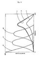
- Fig. 6 shows an example of changes in brightness relative to the amount of ink ejected per unit area when color inks are ejected each independently onto a white printing paper, in which the amount of ink ejected (unit: %) is plotted along the axis of abscissa and brightness L* is plotted along the axis of ordinate (L* is 0 to 100%, the larger, the brighter) .
- the amount of ink ejected corresponds to the ratio of the number of dots ejected relative to the total number of dots per unit area on the printing paper, in other words, the density of dots relative to the printing paper.
- Brightness change curves differ depending on components even in the case of inks of the same color and also differ depending on the type of printing paper to be printed.
- the brightness represents the brightness of the printing paper itself, but assumes a value somewhat smaller than 100%.
- the color ink K is ejected 100%, that is, when it is ejected all dots per unit area relative to the printing paper, the brightness becomes the lowest, but assumes a value somewhat larger than 0%.
- the brightness L* of each color ink lowers according to the amount of ink ejected while describing a downwardly expanded curve.
- C and M exhibit similar changes in brightness and Y is higher in brightness than C and M.
- the color inks c and m low in saturation exhibit similar changes in brightness and their brightnesses lie between the brightnesses of C and M and the brightness of Y.
- the color ink k1 which is a light black color ink exhibits a change in brightness close to that of the color inks C and M.
- the color ink k2 which is a light black color ink exhibits a change in brightness close to that of the color inks c and m.
- the densities of the color inks k1 and k2 may be set to various values. For example, the density of k2 may be set so as to exhibit a change in brightness close to that of C and M or close to that of Y.
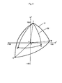
- a color region (GAMUT) capable of being color-reproduced using plural color inks having the above properties is shown schematically in a projected state onto an a*L* plane in an L*a*b* space which is an absolute color space.
- Fig. 8 illustrates this color region schematically in a projected state onto an a*b* plane.
- L* provided on the vertical axis in Fig. 7 represents the above brightness, while a* and b* (unit: %) in Figs. 7 and 8 represent hue and saturation. Saturation is represented in terms of a distance from the center (the position of K) in Fig. 8, while hue is represented in terms of a direction from the center in the same figure.
- the color region in color printing is indicated with a solid line, while the color region in monochromatic image printing is indicated with a dotted line. That the color region is represented by L*a*b* is a mere example and it may be represented by CIExy chromaticity diagram for example.
- cyan and magenta color inks C, M low in both saturation and density
- cyan and magenta color inks be low in density insofar as they are low in saturation.
- the color region which is color-reproduced falls under such regions as indicated with dotted lines in Figs. 7 and 8.
- C represents coordinates which are minus in both a* and b*
- M represents coordinates close to +100 in a* axis direction
- Y represents coordinates close to +100 in b* axis direction.
- the chromatic inks c and m low in saturation assume positions closer to L* axis rather than C and M. According to an actual measurement, the positions of c and m in Fig.
- the achromatic color ink K high in density represents coordinates close to 0 on L* axis.
- the achromatic color inks k1 and k2 low in density represent coordinates which become larger in L* in this order on L* axis.
- a color region S1 capable of being color-reproduced is a space surrounded with C, M, Y, K and coordinates W of the printing paper itself.
- Color-reproducible color regions substantially in cyan and magenta directions in color printing are indicated with solid line arrows in the figures.
- a color-reproducible color region S2 corresponds to a space surrounded with c, m, Y, K and coordinates W of the printing paper itself.
- LUTs 2 and 3 for monochromatic image printing are tables in which RGB bit map data are correlated with color data of 256 gray scales with respect to each of K, k1, k2, Y, c, and m. That is, in the color-reproducible color region S2 which has been narrowed substantially in cyan and magenta directions there is made color reproduction using 256 gray scales. Since in color printing there is made color reproduction using 256 gray scales in the color-reproducible color region S1 which is not narrowed, color reproduction can be done in monochromatic image printing while enhancing the gradation characteristic substantially in cyan and magenta directions. In other words, resolution substantially in cyan and magenta directions is improved. That is, the color tone of a monochromatic image printed can be adjusted minutely with respect to cyan and magenta color components.
- the color-reproducible color region S2 is wide substantially in the direction of yellow.
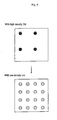
- Fig. 9 is a schematic diagram wherein dots formed on printing paper are compared between the use of C and M high in both saturation and density and the use of c and m low in both saturation and density.
- dots of c and m are mixed in dots of K, k1 and k2.
- the ratio between the number of dots in the use of C and M high in both saturation and density and the number of dots in the use of c and m low in both saturation and density may be changed according to properties of color inks and the ratios of dot number shown in the figure is merely one example.
- Fig. 10 shows the amounts of color inks K, k1, k2, Y, c, and m used in terms of gradation values relative to the brightness of the monochromatic image with saturation assumed to be zero (achromatic 256-gray scale bit map data).
- a hue is created using the color inks c, m, and Y.
- RGB bit map data are converted to color data of K, k1, k2, Y, c, and m with use of such a LUT as affords the illustrated relation.
- chromatic color inks c, m, Y are used in a high brightness portion, while Black color inks are used in a low brightness portion.
- Printing is performed using one or a combination of plural Black color inks. Since Black color inks comprise the color inks K, k1, and k2 different in density, it is possible to select an appropriate Black color ink according to the brightness of image. Further, by using light black color inks k1 and k2, it is possible to diminish the gap in brightness at the time of replacing various chromatic color inks with Black color inks.
- the amounts of inks shown in Fig. 10 are based on the use of LUT2 with priority given to high image quality in monochromatic image printing.
- LUT3 With priority given to running cost, the curves which represent the amounts of color inks K, k1, and k2 used shift in a higher brightness direction, as shown in Fig. 11.
- the amounts of chromatic color inks c, m, and Y decrease. That is, by switching LUTs 2 and 3 from one to the other, it is possible to change the ratio between plural Black color inks and other color inks.
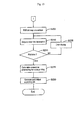
- Figs. 12 to 14 are flowcharts showing an outline of processings performed by the personal computer 10 in the printing system 100. It is assumed that before execution of the illustrated processing flow, ink cartridges of C and M are loaded as ink cartridges 28b and 28c to cartridge holders 28 in color printing and ink cartridges of k1 and k2 are loaded as ink cartridges 28b and 28c in monochromatic image printing, both by a user.
- APL has a printing function for APL.
- the printer driver causes the print setting acquiring module m4 to operate under control of the function control module and performs a processing for displaying a print interface main screen (not shown) (step S105).
- a print interface main screen not shown
- the printer driver causes the print setting acquiring module m4 to operate under control of the function control module and performs a processing for displaying a print interface main screen (not shown) (step S105).
- a print interface main screen not shown
- step S120 If the print type setting button is clicked by the mouse 16b, the processing flow advances to step S120 and there is displayed a print type setting screen 200 shown in Fig. 15. On the left-hand side of the screen 200 are displayed a print type selecting field 201, OK button 205, and Cancel button 206.
- the print type selecting field 201 In the print type selecting field 201, only either "Color” or "Monochromatic Image” can be selected and inputted by the mouse 16b.
- the ratios of color inks are set so as to give such amounts of inks used as shown in Fig. 10, while when “Priority given to Running Cost” is selected, the ratios of color inks are set so as to give such amounts of inks used as shown in Fig. 11.
- a hue setting field 203 and an application quantity setting field 204 are displayed on the right-hand side of the print type setting screen 200.
- the hue setting field 203 are displayed a hue ring 203a including cyan, magenta, and yellow (C, M, and Y, respectively, in the figure) and a needle 203b which can rotate with the center of the hue ring 203a as a rotational center.
- the needle 203b can be positioned to a desired hue on the hue ring 203a.
- the positions of "Sepia,” “Warm,” and “Cool” are shown in the hue setting field 203, so that the needle 203b can be set to those positions easily.
- the application quantity setting field 204 are displayed a linear groove 204a and an arrow 204b which can slide along the groove 204a.
- a black-and-white image with no hue applied thereto is set, while as the arrow 204b is moved rightwards, there is set a monochromatic image in such a manner that the hue set in the hue setting field 203 becomes stronger.
- step S125 the print type setting screen 200 is erased and the processing flow returns to step S105, in which the print interface main screen is again displayed.
- a Cancel button 206 is clicked, the information inputted by operation is destroyed, the print type setting screen 200 is erased, and the processing flow returns to step S105.
- steps S120 to S125 not only constitute a print type acquiring means which acquires a print type of either monochromatic image printing or color printing, but also constitute a ratio setting acquiring means which acquires a ratio setting between plural Black color inks and other color inks.
- step S115 If the cancel button on the print interface main screen is clicked at step S115, the processing flow advances to step S130, which cancels the thus obtained print parameters and end this processing flow.
- step S135 the print data acquiring module m1 is operated to acquire print data D1 generated by APL through GDI.
- the intermediate file generating module m2 is operated to generate an intermediate file on the basis of the acquired print data, which file is stored in the hard disc 14a temporarily (step S140).
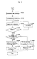
- step S145 the print job generating module m3 is operated, causing the processing flow to branch according to the set print type (step S145). If "Color” is selected and inputted in the print type selecting field 201, the processing flow advances to step 5205 in Fig. 13, while if "monochromatic image” is selected and inputted in the print type selecting field 201, the processing flow advances to step S305 in Fig. 14.
- step S205 the intermediate file D2 is read and RGB bit map conversion is performed on the basis of the intermediate language included in the intermediate file D2 to generate RGB bit map data D3 on RAM 13.
- ink cartridges 28b and 28c in monochromatic image printing ink cartridges of k1 and k2 are loaded instead of ink cartridges of C and M, so there may occur a case where ink cartridges of C and M are not loaded despite the processing being carried out is for color printing.
- a processing for acquiring from the printer 20 color ink information which includes such information pieces as ink colors and residual amounts in the loaded ink cartridges and for checking whether all of the color inks necessary for printing are employable or not.
- step S210 the above color ink information is acquired from the printer 20. More specifically, when a request for acquiring color ink information is outputted from the personal computer 10 to the printer 20 through the printer I/F 19, the printer 20 acquires this request, generates color ink information from information indicating ink color and residual amount in each of ink cartridges, and outputs the generated information to the personal computer 10 through communication I/O 26. In this way the personal computer 10 can acquire the color ink information outputted from the printer 20.
- step S215 On the basis of the color ink information there is made judgment as to whether color printing can be executed or not (step S215). That is, when all of the ink colors K, c, m, C, M, and Y are included in the color ink information and when the residual amounts of inks in all their ink cartridges are not zero, it is judged that printing can be done. Therefore, for example when ink cartridges of k1 and k2 are loaded as the ink cartridges 28b and 28c, it follows that C and M are not included as ink colors in the color ink information, so the conditions for printing are not satisfied.
- step S215 If the conditions for printing are met in step S215, the processing flow advances to step S225, while if the answer is negative, the flow shifts to step S220.
- step S220 there is made indication on an error display screen to the effect that printing cannot be done and that ink cartridges necessary for color printing should be loaded. Then, after the necessary ink cartridges have been loaded and OK button on the screen is clicked, there are again conducted the processings of steps S210 to S215. In step S220, this processing flow may be ended after display of the error display screen.
- step S225 there is performed a color data conversion processing for color printing. More specifically, RGB bit map data D3 is converted to color data D5 which comprises six kinds of K, C, M, Y, c, and m. This processing is carried out by converting 256-gray scale bit map data of each of R, G, B into 256-gray scale color data of each of K, C, M, Y, c, and m with reference to the foregoing LUT1 for color printing.
- the color data D5 is binarized and a printing job D7 corresponding to K, C, M, Y, c, and m is generated and transmitted to the printer 20 (step S230). This processing flow is now ended. Then, the printer 20 acquires the printing job D7 and drives the print head 30 on the basis of the printing job D7 for form dots of color inks, thereby performing color printing.
- step S145 in Fig. 12 the processing flow advances from step S145 in Fig. 12 to step S305 in Fig. 14, in which the intermediate file D2 is read and is converted to achromatic bit map data on the basis of the intermediate language included in the intermediate file D2.
- the printing data D1 acquired may be data of an image not containing information on hue or may be data for a color image.
- the processing to be carried out is to convert the gradation data into brightness data to afford achromatic bit map data.
- the brightness data in question can be obtained by various other methods.
- gradation data may be averaged or added to obtain brightness data.
- the processing for conversion to brightness data may be omitted.
- the achromatic bit map data is converted to RGB bit map data with hue not applied thereto and a hue is applied thereto on the basis of both hue and amount thereof to be applied which have been acquired from the hue setting field 203 and application quantity setting field 204, thereby making conversion into RGB bit map data D4 with hue applied thereto (step S310).
- the RGB bit map data D4 is generated on RAM 13. Components (R0, G0, B0) of R, G, B included in the RGB bit map data with hue not applied thereto can be obtained from the brightness data L in accordance with a predetermined conversion expression.
- R R0 - a ⁇ A0 + r ⁇ A0
- G G0 - a ⁇ A0 + g ⁇ A0
- B B0 - a ⁇ A0 + b ⁇ A0
- any other method than the use of the above expressions may be used for the conversion of achromatic bit map data into RGB bit map data.
- step S320 the foregoing color ink information is acquired from the printer 20 (step S315).
- step S320 the color ink information it is judged whether it is possible to effect monochromatic image printing. More specifically, if all of K, k1, k2, C, M, and Y are included as ink colors in the color ink information and if all their residual amounts are not zero, there is made judgment that it is possible to effect printing. Therefore, if ink cartridges of C and M are loaded as ink cartridges 28ba and 28c, the conditions for printing are not satisfied.
- step S320 If the answer is affirmative in step S320, the processing flow advances to step S330, while if the answer in step S320 is negative, the flow shifts to step S325.
- step S325 the same error display screen as in step S220 is displayed. After the required ink cartridges are loaded and OK button provided on the screen is clicked, the processings of steps S315 to S320 are again performed.
- step S330 the processing flow is branched in accordance with the setting of ink ratio which has been set. If "Priority given to High Image Quality" is selected and inputted in the ink ratio selecting field 202, the processing flow advances to step S335, in which there is performed a color data conversion processing for priority given to high image quality in monochromatic image printing.
- the LUT2 is a color conversion table for priority given to high image quality in monochromatic image printing. The values of color data of Y, c, m out of the data which constitute the color data D6 become larger than in the use of LUT3.
- the color data D6 is binarized and a printing job D8 corresponding to K, k1, k2, Y, c, and m is generated and transmitted to the printer 20 (step S340). Now this processing flow is ended.
- the printer 20 receives the printing job D8 and actuates the print head 30 on the basis of the printing job D8 to form dots of the color inks K, k1, k2, Y, c, m, thereby printing a monochromatic image.
- step S345 in which there is performed a color data conversion processing for priority given to running cost in monochromatic image printing. More specifically, there is performed a processing for converting 256-gray scale bit map data on each of R, G, B into 256-gray scale color data D6 on each of K, k1, k2, Y, c, m with reference the foregoing LUT3.
- the LUT 3 is a color conversion table for priority given to running cost in monochromatic image printing. The values of color data of K, k1, k2 out of the data which constitute the color data D6 become larger tha n in the use of LUT2.
- step S340 the color data D6 is binarized and a printing job D8 corresponding to K, k1, k2, Y, c, m is generated and transmitted to the printer 20 (step S350). Now this processing flow is ended. On this basis of the printing job D8 the printer 20 forms dots of the color inks K, k1, k2, Y, c, m and thereby print a monochromatic image.
- color reproduction is effected under an enhanced gradation characteristic within a color-reproducible color region while the same color region is narrowed by c and m low in saturation, Y of a high saturation, and K, k1 and k2 which are Black color inks.
- Y of a high saturation is used together with K, k1 and k2 as achromatic inks and c and m low in saturation and monochromatic image printing is performed while the color region is not narrowed substantially in the direction of yellow from the time of color printing.
- the user can set which of monochromatic image printing and color printing is to be performed, and even if the number of loadable ink cartridges is limited, both monochromatic image printing and color printing can be done in the same printing system 100.
- the printing system 100 is convenient.
- the color inks k1 and k2 as light black color inks are provided so that they can be replaced with the color inks C and M high in saturation, it is possible to prevent such printing as is performed using unintended color inks, because printing is performed after making sure that the color inks to be used are required color inks.
- step S305 means for inputting first, achromatic, multi-gradation image data is implemented in steps S135, S140, and S305.
- step S305 a chromatic color image data is inputted, brightnesses of picture elements are determined on the basis of the inputted image data and are used as the above first image data.
- Means for acquiring hue is implemented in steps S105 and S110. But in steps S105 and S110 there also is obtained an application quantity indicative of strength to be applied in addition of hue.
- means for converting the above first image data to the above second image data is implemented by steps S205 and S335 or S345.
- the above first image data is converted to third image data with hue applied to the first image data, followed by conversion to the above second image data. That is, the former conversion is a processing for changing the intensity of hue which is applied correspondingly to the application quantity acquired and is implemented by step S205.
- the third image data is subjected to color conversion to the second image data.
- This conversion is implemented by step S335 or S345.
- the color conversion table utilized at this time corresponds to the range of a color-reproducible color region which is determined by a saturation capable of being reproduced by the foregoing cyan color ink, a saturation capable of being reproduced by the foregoing magenta color ink, and a saturation capable of being reproduced by the foregoing yellow color ink. That is, a color space after the conversion by the color conversion table corresponds to the range of the color region referred to above.
- the above third image data has a hue
- the number of color data capable of being obtained is within the range of the maximum gradation number of the first image data.
- gradation value of the first image data it is possible to make conversion to the second image data of multi-gradation with the acquired hue applied thereto.
- the color conversion table plural Black color inks different in density are premised and plural such color conversion tables are provided so as to give different amounts of the Black color inks used.
- Such plural color conversion tables correspond respectively to conversion processings for priority given to high image quality and for priority given to running cost.
- means for acquiring a selection result corresponding to changes in the amounts of the Black color inks used is implemented by steps S105 and S110.
- the processing which selects any of the color conversion tables on the basis of the selection result and which causes color conversion to be effected using the selected color conversion table is implemented by step 330.
- means for converting the above second image data to the foregoing printing data of low gradation is implemented as a color data binarizing processing in steps S340 and S350.
- the printing system according to the present invention may be implemented in various constructions.
- the printer may be integral with the computer, or may be a dedicated printer for printing only monochromatic images. It is not always necessary to have both color inks c and m. Having only one of the color inks c and m will do. Also in this case, monochromatic image printing can be done without narrowing the color region substantially in the direction of yellow from the time of color printing and it is possible to print a monochromatic image of a high image quality having a sufficient power of expression while ensuring a sufficient selection range of saturation. Moreover, the printer is not limited to the printer using piezoelectric elements for the ejection of color inks to form dots.
- a bubble type printer wherein bubbles are generated within ink passages and color inks are ejected thereby.
- a printer wherein the size of dots formed is variable, such as what is called a variable printer.
- plural color inks may be filled into a single ink cartridge.
- an ink cartridge for color printing filled with all of the color inks K, C, M, Y, c, m and an ink cartridge for monochromatic image printing filled with all of the color inks K, k1, k2, Y, c, m and the two ink cartridges are replaced one with the other.
- ink cartridges replaceably is merely one example of construciton.
- the color inks k1 or k2 may be provided replaceably with only the color ink C or with only the color ink M.
- the color ink k1 may be provided replaceably with the color ink C or M.
- the execution of the processings is not limited to within the personal computer, but a part or the whole thereof may be executed by the printer or using a dedicated image processor.
- the printer driver applies a hue to an achromatic image so as to give a desired tone in monochromatic image printing, but for generating printing data on a monochromatic image with hue applied thereto by APL, the foregoing steps S305 to S310 may be substituted by a processing which involves making RGB bit map conversion directly from an intermediate file to generate RGB bit map data.
- step S315 and subsequent processings if color reproduction is performed under an enhanced gradation characteristic in a color-reproducible color region while narrowing the same color region using c and m low in saturation, Y of a high saturation, and K, k1, and k2 which are Black color inks, it is possible to print a monochromatic image of a high quality having a sufficient power of expression while ensuring a sufficient selection range of saturation.
- the processing to be performed in case of applying a hue so as to give a desired hue is not limited to the processing wherein there is made conversion to such color data as K, Y, c, and m after generation of RGB bit map data with the hue applied thereto. There may be conducted a processing such that the color data of Y, c, and m are corrected for the application of hue after conversion from unhued, achromatic bit map data to such color data as K, Y, c, and m.
- the processing for generating the color data is not limited to the processing that uses different LUTs.
- the color data may be generated by an arithmetic processing for conversion from one color data to the other color data.
- an arithmetic processing which converts a portion of the color data Y, c, and m into color data of an achromatic color ink such as k2.
- the correction coefficients A1 to A4 may be determined according to densities of the color inks k2, Y, c, and m.
- the present invention it is possible to provide a printing system which, in any of various modes, can print a monochromatic image of a high image quality having a sufficient power of expression while ensuring a sufficient selection range of saturation.
- the printing system is also applicable as a printing method and program for the system, as well as a medium which stores the program.
Landscapes
- Engineering & Computer Science (AREA)
- Multimedia (AREA)
- Signal Processing (AREA)
- Ink Jet (AREA)
- Facsimile Image Signal Circuits (AREA)
- Color, Gradation (AREA)
- Particle Formation And Scattering Control In Inkjet Printers (AREA)
- Accessory Devices And Overall Control Thereof (AREA)
- Color Image Communication Systems (AREA)
Applications Claiming Priority (2)
| Application Number | Priority Date | Filing Date | Title |
|---|---|---|---|
| JP2001236322 | 2001-08-03 | ||
| JP2001236322A JP3582649B2 (ja) | 2001-08-03 | 2001-08-03 | 印刷装置、印刷方法、印刷装置の制御プログラムおよび印刷装置の制御プログラムを記録した媒体 |
Publications (3)
| Publication Number | Publication Date |
|---|---|
| EP1289269A2 true EP1289269A2 (fr) | 2003-03-05 |
| EP1289269A3 EP1289269A3 (fr) | 2005-01-05 |
| EP1289269B1 EP1289269B1 (fr) | 2007-10-17 |
Family
ID=19067610
Family Applications (1)
| Application Number | Title | Priority Date | Filing Date |
|---|---|---|---|
| EP02017614A Expired - Lifetime EP1289269B1 (fr) | 2001-08-03 | 2002-08-05 | Système d'impression, procédé d'impression, et programme de commande pour le système d'impression |
Country Status (6)
| Country | Link |
|---|---|
| US (4) | US6880915B2 (fr) |
| EP (1) | EP1289269B1 (fr) |
| JP (1) | JP3582649B2 (fr) |
| CN (1) | CN1250400C (fr) |
| AT (1) | ATE376325T1 (fr) |
| DE (1) | DE60222975T2 (fr) |
Cited By (4)
| Publication number | Priority date | Publication date | Assignee | Title |
|---|---|---|---|---|
| EP1560419A2 (fr) | 2004-01-30 | 2005-08-03 | Canon Kabushiki Kaisha | Procédé, système et programme de formation d'image |
| US7701489B1 (en) | 2003-05-27 | 2010-04-20 | Apple Inc. | Method and apparatus for color correction |
| AU2005292046B2 (en) * | 2004-09-29 | 2010-09-23 | Apple Inc. | Methods and apparatuses for aesthetically enhanced image conversion |
| US7916941B2 (en) | 2003-08-29 | 2011-03-29 | Apple Inc. | Methods and apparatuses for restoring color and enhancing electronic images |
Families Citing this family (33)
| Publication number | Priority date | Publication date | Assignee | Title |
|---|---|---|---|---|
| AUPO850597A0 (en) * | 1997-08-11 | 1997-09-04 | Silverbrook Research Pty Ltd | Image processing method and apparatus (art01a) |
| US8042740B2 (en) * | 2000-11-24 | 2011-10-25 | Metrologic Instruments, Inc. | Method of reading bar code symbols on objects at a point-of-sale station by passing said objects through a complex of stationary coplanar illumination and imaging planes projected into a 3D imaging volume |
| JP3582649B2 (ja) * | 2001-08-03 | 2004-10-27 | セイコーエプソン株式会社 | 印刷装置、印刷方法、印刷装置の制御プログラムおよび印刷装置の制御プログラムを記録した媒体 |
| JP2004142423A (ja) * | 2002-08-29 | 2004-05-20 | Seiko Epson Corp | モノクローム画像印刷のための色調設定 |
| JP4307095B2 (ja) * | 2003-02-05 | 2009-08-05 | キヤノン株式会社 | 色変換方法及びプロファイル作成方法 |
| JP4158563B2 (ja) * | 2003-03-12 | 2008-10-01 | ブラザー工業株式会社 | 両面記録装置 |
| JP4356697B2 (ja) * | 2003-07-22 | 2009-11-04 | セイコーエプソン株式会社 | モノクローム画像のための色調設定 |
| DE602004016603D1 (de) * | 2003-08-11 | 2008-10-30 | Canon Kk | Bildaufzeichnungsgerät, Verfahren zur Bilderzeugung und Programm zur Durchführung des Verfahrens |
| JP2005088434A (ja) * | 2003-09-18 | 2005-04-07 | Minolta Co Ltd | 画像形成装置 |
| JP4797322B2 (ja) * | 2003-09-24 | 2011-10-19 | セイコーエプソン株式会社 | 印刷装置及び印刷方法 |
| US7255412B2 (en) * | 2003-09-30 | 2007-08-14 | Fujifilm Corporation | Image forming apparatus and method |
| JP2005175876A (ja) * | 2003-12-11 | 2005-06-30 | Ricoh Co Ltd | 色信号処理方法および装置、カラープロファイル作成方法、プログラムおよび記録媒体 |
| JP4341495B2 (ja) * | 2004-03-02 | 2009-10-07 | セイコーエプソン株式会社 | 画像に付与する色調の設定 |
| JP2005295508A (ja) * | 2004-03-08 | 2005-10-20 | Seiko Epson Corp | カラー画像のモノクローム画像化 |
| JP2006074162A (ja) * | 2004-08-31 | 2006-03-16 | Seiko Epson Corp | カラー画像とモノクロ画像の画像処理 |
| JP2006101444A (ja) * | 2004-09-30 | 2006-04-13 | Canon Inc | 画像形成装置及びその制御方法 |
| JP4561398B2 (ja) | 2005-02-23 | 2010-10-13 | セイコーエプソン株式会社 | 濃淡インクを使用する印刷のためのルックアップテーブルの生成 |
| JP4325575B2 (ja) * | 2005-03-18 | 2009-09-02 | セイコーエプソン株式会社 | モノトーン画像のための基準色調設定 |
| US7636178B2 (en) * | 2005-04-15 | 2009-12-22 | Canon Kabushiki Kaisha | Image processing apparatus, printing apparatus and image processing method |
| JP2007106111A (ja) * | 2005-09-16 | 2007-04-26 | Ricoh Co Ltd | 画像形成装置及び画像形成方法 |
| JP4752535B2 (ja) * | 2006-02-15 | 2011-08-17 | 富士ゼロックス株式会社 | 画像処理装置、画像処理方法、及び画像処理プログラム |
| JP4208911B2 (ja) * | 2006-08-31 | 2009-01-14 | キヤノン株式会社 | 画像処理装置及びその方法、並びに、コンピュータプログラムおよび記録媒体 |
| US20090007128A1 (en) * | 2007-06-28 | 2009-01-01 | International Business Machines Corporation | method and system for orchestrating system resources with energy consumption monitoring |
| US8145918B2 (en) * | 2007-06-28 | 2012-03-27 | International Business Machines Corporation | Monitoring system processes energy consumption |
| JP4924944B2 (ja) * | 2007-09-19 | 2012-04-25 | 富士ゼロックス株式会社 | 画像形成装置 |
| JP4956356B2 (ja) * | 2007-10-02 | 2012-06-20 | キヤノン株式会社 | 画像処理装置及び画像処理方法 |
| JP2010076355A (ja) * | 2008-09-29 | 2010-04-08 | Seiko Epson Corp | 印刷装置、プログラム、および、プリンタドライバ |
| US8250384B2 (en) * | 2009-01-05 | 2012-08-21 | International Business Machines Corporation | Optimizer mechanism to increase battery length for mobile devices |
| JP5441525B2 (ja) * | 2009-07-01 | 2014-03-12 | キヤノン株式会社 | 画像処理方法及び画像処理装置 |
| BR112013031472B1 (pt) | 2011-06-08 | 2021-05-18 | Hewlett-Packard Development Company, L.P. | método de gerenciamento de fluxo de dados para um dispositivo de impressão e sistema para aumentar o fluxo de dados para um dispositivo de impressão |
| US9596372B2 (en) * | 2015-07-29 | 2017-03-14 | Kabushiki Kaisha Toshiba | Image processing apparatus, image processing method and image forming apparatus |
| JP2017200742A (ja) * | 2016-05-06 | 2017-11-09 | 株式会社リコー | 画像形成システム、画像形成装置、画像形成方法、画像形成プログラム |
| CN107357538B (zh) * | 2017-08-01 | 2020-02-04 | 凌云光技术集团有限责任公司 | 一种获取印刷品的阶调值的方法及装置 |
Citations (7)
| Publication number | Priority date | Publication date | Assignee | Title |
|---|---|---|---|---|
| US4855753A (en) * | 1987-06-19 | 1989-08-08 | Canon Kabushiki Kaisha | Method of ink jet recording and ink jet recording apparatus |
| US4860026A (en) * | 1987-06-25 | 1989-08-22 | Canon Kabushiki Kaisha | Halftone image recording method using recording data having a plurality of concentrations for one color |
| US4952942A (en) * | 1986-05-29 | 1990-08-28 | Canon Kabushiki Kaisha | Ink jet recording method with improved tone by recording yellow first |
| US4959659A (en) * | 1983-03-08 | 1990-09-25 | Canon Kabushiki Kaisha | Color picture forming apparatus and method |
| EP0401023A2 (fr) * | 1989-06-01 | 1990-12-05 | Canon Kabushiki Kaisha | Système d'enregistrement d'images et appareil pour celui-ci |
| US5221954A (en) * | 1992-10-01 | 1993-06-22 | Xerox Corporation | Single pass full color printing system using a quad-level xerographic unit |
| EP0660589A2 (fr) * | 1993-12-21 | 1995-06-28 | Nec Corporation | Appareil de formation d'images en couleur capable de produire une qualité d'image uniforme et solide pour les milieux d'enregistrement divers |
Family Cites Families (9)
| Publication number | Priority date | Publication date | Assignee | Title |
|---|---|---|---|---|
| US4672432A (en) | 1983-04-28 | 1987-06-09 | Canon Kabushiki Kaisha | Method for recording a color image using dots of colorants of different densities |
| JP3133750B2 (ja) * | 1989-03-24 | 2001-02-13 | キヤノン株式会社 | インクジェットカートリッジおよびそれを用いるインクジェット記録装置 |
| US5825377A (en) * | 1993-04-28 | 1998-10-20 | Canon Kabushiki Kaisha | Method and apparatus for ink-jet recording with inks having different densities |
| US5742306A (en) * | 1995-07-31 | 1998-04-21 | Hewlett-Packard Company | Imaging cartridge system for inkjet printing mechanisms |
| US6290762B1 (en) | 1996-09-10 | 2001-09-18 | Macdermid-Acumen, Inc. | Method of selecting an ink set of an ink jet printer |
| US5858075A (en) * | 1997-03-03 | 1999-01-12 | Hewlett-Packard Company | Dye set for improved ink-jet image quality |
| US6145961A (en) * | 1997-09-04 | 2000-11-14 | Seiko Epson Corporation | Ink-jet printing apparatus and ink reservoir unit attached thereto |
| JP4395943B2 (ja) * | 1998-11-26 | 2010-01-13 | セイコーエプソン株式会社 | 印刷装置およびその情報の管理方法 |
| JP3582649B2 (ja) * | 2001-08-03 | 2004-10-27 | セイコーエプソン株式会社 | 印刷装置、印刷方法、印刷装置の制御プログラムおよび印刷装置の制御プログラムを記録した媒体 |
-
2001
- 2001-08-03 JP JP2001236322A patent/JP3582649B2/ja not_active Expired - Fee Related
-
2002
- 2002-08-01 US US10/209,663 patent/US6880915B2/en not_active Expired - Lifetime
- 2002-08-02 CN CNB021282072A patent/CN1250400C/zh not_active Expired - Fee Related
- 2002-08-05 DE DE60222975T patent/DE60222975T2/de not_active Expired - Lifetime
- 2002-08-05 EP EP02017614A patent/EP1289269B1/fr not_active Expired - Lifetime
- 2002-08-05 AT AT02017614T patent/ATE376325T1/de not_active IP Right Cessation
-
2004
- 2004-10-27 US US10/973,287 patent/US7488053B2/en active Active
-
2009
- 2009-01-05 US US12/348,463 patent/US7735964B2/en not_active Expired - Fee Related
-
2010
- 2010-04-15 US US12/760,595 patent/US20100199883A1/en not_active Abandoned
Patent Citations (7)
| Publication number | Priority date | Publication date | Assignee | Title |
|---|---|---|---|---|
| US4959659A (en) * | 1983-03-08 | 1990-09-25 | Canon Kabushiki Kaisha | Color picture forming apparatus and method |
| US4952942A (en) * | 1986-05-29 | 1990-08-28 | Canon Kabushiki Kaisha | Ink jet recording method with improved tone by recording yellow first |
| US4855753A (en) * | 1987-06-19 | 1989-08-08 | Canon Kabushiki Kaisha | Method of ink jet recording and ink jet recording apparatus |
| US4860026A (en) * | 1987-06-25 | 1989-08-22 | Canon Kabushiki Kaisha | Halftone image recording method using recording data having a plurality of concentrations for one color |
| EP0401023A2 (fr) * | 1989-06-01 | 1990-12-05 | Canon Kabushiki Kaisha | Système d'enregistrement d'images et appareil pour celui-ci |
| US5221954A (en) * | 1992-10-01 | 1993-06-22 | Xerox Corporation | Single pass full color printing system using a quad-level xerographic unit |
| EP0660589A2 (fr) * | 1993-12-21 | 1995-06-28 | Nec Corporation | Appareil de formation d'images en couleur capable de produire une qualité d'image uniforme et solide pour les milieux d'enregistrement divers |
Cited By (9)
| Publication number | Priority date | Publication date | Assignee | Title |
|---|---|---|---|---|
| US7701489B1 (en) | 2003-05-27 | 2010-04-20 | Apple Inc. | Method and apparatus for color correction |
| US7916941B2 (en) | 2003-08-29 | 2011-03-29 | Apple Inc. | Methods and apparatuses for restoring color and enhancing electronic images |
| US8224086B2 (en) | 2003-08-29 | 2012-07-17 | Apple Inc. | Methods and apparatuses for restoring color and enhancing electronic images |
| US8538147B2 (en) | 2003-08-29 | 2013-09-17 | Apple Inc. | Methods and appartuses for restoring color and enhancing electronic images |
| EP1560419A2 (fr) | 2004-01-30 | 2005-08-03 | Canon Kabushiki Kaisha | Procédé, système et programme de formation d'image |
| EP1560419A3 (fr) * | 2004-01-30 | 2008-05-28 | Canon Kabushiki Kaisha | Procédé, système et programme de formation d'image |
| US7936481B2 (en) * | 2004-01-30 | 2011-05-03 | Canon Kabushiki Kaisha | Method, system and program for forming an image |
| AU2005292046B2 (en) * | 2004-09-29 | 2010-09-23 | Apple Inc. | Methods and apparatuses for aesthetically enhanced image conversion |
| US8462384B2 (en) | 2004-09-29 | 2013-06-11 | Apple Inc. | Methods and apparatuses for aesthetically enhanced image conversion |
Also Published As
| Publication number | Publication date |
|---|---|
| DE60222975D1 (de) | 2007-11-29 |
| CN1405004A (zh) | 2003-03-26 |
| CN1250400C (zh) | 2006-04-12 |
| US7488053B2 (en) | 2009-02-10 |
| EP1289269A3 (fr) | 2005-01-05 |
| JP2003039738A (ja) | 2003-02-13 |
| US20030038870A1 (en) | 2003-02-27 |
| US6880915B2 (en) | 2005-04-19 |
| US20090195602A1 (en) | 2009-08-06 |
| US20100199883A1 (en) | 2010-08-12 |
| US20050219618A1 (en) | 2005-10-06 |
| ATE376325T1 (de) | 2007-11-15 |
| JP3582649B2 (ja) | 2004-10-27 |
| EP1289269B1 (fr) | 2007-10-17 |
| US7735964B2 (en) | 2010-06-15 |
| DE60222975T2 (de) | 2008-07-24 |
Similar Documents
| Publication | Publication Date | Title |
|---|---|---|
| EP1289269B1 (fr) | Système d'impression, procédé d'impression, et programme de commande pour le système d'impression | |
| US7237866B2 (en) | Image printing using print quality enhancing ink | |
| US7883168B2 (en) | Reduction of dependence of color appearance on light source | |
| JP3925431B2 (ja) | 有彩1次色インクと有彩2次色インクとを含む複数のインク成分への分版処理 | |
| US5615312A (en) | Color management system having business graphics rendering mode | |
| JP4240210B2 (ja) | 印刷制御装置、印刷制御方法および印刷制御プログラム | |
| JP4003046B2 (ja) | 印刷制御装置、印刷制御方法、印刷システム、印刷制御プログラムおよび印刷制御プログラムを記録した媒体 | |
| JP4251003B2 (ja) | 有彩1次色インクと有彩2次色インクとを含む複数のインク成分への分版処理 | |
| JP2005014586A (ja) | 印刷制御装置、印刷制御方法および印刷制御プログラム | |
| JP3894127B2 (ja) | 有彩1次色インクと有彩2次色インクとを含む複数のインク成分への分版処理 | |
| JP4650535B2 (ja) | 有彩1次色インクと有彩2次色インクとを用いた印刷 | |
| JP2011055395A (ja) | 白色インクを含む複数色のインクを用いた印刷 | |
| JP4273318B2 (ja) | 色変換装置、色変換方法、印刷制御プログラム | |
| JP4403709B2 (ja) | 有彩1次色インクと有彩2次色インクとを含む複数のインク成分への分版処理 | |
| JP2005007591A (ja) | 印刷制御装置、印刷制御方法、印刷制御プログラムおよびインク量決定方法 | |
| JP2003296087A (ja) | 印刷制御装置、印刷制御方法、印刷制御プログラム、印刷制御プログラムを記録した媒体、色変換装置、色変換方法、3次元色変換テーブルの作成方法および3次元色変換テーブル |
Legal Events
| Date | Code | Title | Description |
|---|---|---|---|
| PUAI | Public reference made under article 153(3) epc to a published international application that has entered the european phase |
Free format text: ORIGINAL CODE: 0009012 |
|
| AK | Designated contracting states |
Kind code of ref document: A2 Designated state(s): AT BE BG CH CY CZ DE DK EE ES FI FR GB GR IE IT LI LU MC NL PT SE SK TR |
|
| AX | Request for extension of the european patent |
Extension state: AL LT LV MK RO SI |
|
| PUAL | Search report despatched |
Free format text: ORIGINAL CODE: 0009013 |
|
| AK | Designated contracting states |
Kind code of ref document: A3 Designated state(s): AT BE BG CH CY CZ DE DK EE ES FI FR GB GR IE IT LI LU MC NL PT SE SK TR |
|
| AX | Request for extension of the european patent |
Extension state: AL LT LV MK RO SI |
|
| 17P | Request for examination filed |
Effective date: 20050203 |
|
| 17Q | First examination report despatched |
Effective date: 20050609 |
|
| AKX | Designation fees paid |
Designated state(s): AT BE BG CH CY CZ DE DK EE ES FI FR GB GR IE IT LI LU MC NL PT SE SK TR |
|
| GRAP | Despatch of communication of intention to grant a patent |
Free format text: ORIGINAL CODE: EPIDOSNIGR1 |
|
| GRAS | Grant fee paid |
Free format text: ORIGINAL CODE: EPIDOSNIGR3 |
|
| GRAA | (expected) grant |
Free format text: ORIGINAL CODE: 0009210 |
|
| RAP1 | Party data changed (applicant data changed or rights of an application transferred) |
Owner name: SEIKO EPSON CORPORATION |
|
| AK | Designated contracting states |
Kind code of ref document: B1 Designated state(s): AT BE BG CH CY CZ DE DK EE ES FI FR GB GR IE IT LI LU MC NL PT SE SK TR |
|
| REG | Reference to a national code |
Ref country code: GB Ref legal event code: FG4D |
|
| REG | Reference to a national code |
Ref country code: CH Ref legal event code: EP |
|
| REG | Reference to a national code |
Ref country code: IE Ref legal event code: FG4D |
|
| REF | Corresponds to: |
Ref document number: 60222975 Country of ref document: DE Date of ref document: 20071129 Kind code of ref document: P |
|
| NLV1 | Nl: lapsed or annulled due to failure to fulfill the requirements of art. 29p and 29m of the patents act | ||
| PG25 | Lapsed in a contracting state [announced via postgrant information from national office to epo] |
Ref country code: LI Free format text: LAPSE BECAUSE OF FAILURE TO SUBMIT A TRANSLATION OF THE DESCRIPTION OR TO PAY THE FEE WITHIN THE PRESCRIBED TIME-LIMIT Effective date: 20071017 Ref country code: ES Free format text: LAPSE BECAUSE OF FAILURE TO SUBMIT A TRANSLATION OF THE DESCRIPTION OR TO PAY THE FEE WITHIN THE PRESCRIBED TIME-LIMIT Effective date: 20080128 Ref country code: CH Free format text: LAPSE BECAUSE OF FAILURE TO SUBMIT A TRANSLATION OF THE DESCRIPTION OR TO PAY THE FEE WITHIN THE PRESCRIBED TIME-LIMIT Effective date: 20071017 Ref country code: SE Free format text: LAPSE BECAUSE OF FAILURE TO SUBMIT A TRANSLATION OF THE DESCRIPTION OR TO PAY THE FEE WITHIN THE PRESCRIBED TIME-LIMIT Effective date: 20080117 Ref country code: NL Free format text: LAPSE BECAUSE OF FAILURE TO SUBMIT A TRANSLATION OF THE DESCRIPTION OR TO PAY THE FEE WITHIN THE PRESCRIBED TIME-LIMIT Effective date: 20071017 |
|
| REG | Reference to a national code |
Ref country code: CH Ref legal event code: PL |
|
| PG25 | Lapsed in a contracting state [announced via postgrant information from national office to epo] |
Ref country code: BG Free format text: LAPSE BECAUSE OF FAILURE TO SUBMIT A TRANSLATION OF THE DESCRIPTION OR TO PAY THE FEE WITHIN THE PRESCRIBED TIME-LIMIT Effective date: 20080117 Ref country code: PT Free format text: LAPSE BECAUSE OF FAILURE TO SUBMIT A TRANSLATION OF THE DESCRIPTION OR TO PAY THE FEE WITHIN THE PRESCRIBED TIME-LIMIT Effective date: 20080317 |
|
| PG25 | Lapsed in a contracting state [announced via postgrant information from national office to epo] |
Ref country code: AT Free format text: LAPSE BECAUSE OF FAILURE TO SUBMIT A TRANSLATION OF THE DESCRIPTION OR TO PAY THE FEE WITHIN THE PRESCRIBED TIME-LIMIT Effective date: 20071017 |
|
| ET | Fr: translation filed | ||
| PG25 | Lapsed in a contracting state [announced via postgrant information from national office to epo] |
Ref country code: CZ Free format text: LAPSE BECAUSE OF FAILURE TO SUBMIT A TRANSLATION OF THE DESCRIPTION OR TO PAY THE FEE WITHIN THE PRESCRIBED TIME-LIMIT Effective date: 20071017 Ref country code: DK Free format text: LAPSE BECAUSE OF FAILURE TO SUBMIT A TRANSLATION OF THE DESCRIPTION OR TO PAY THE FEE WITHIN THE PRESCRIBED TIME-LIMIT Effective date: 20071017 |
|
| PLBE | No opposition filed within time limit |
Free format text: ORIGINAL CODE: 0009261 |
|
| STAA | Information on the status of an ep patent application or granted ep patent |
Free format text: STATUS: NO OPPOSITION FILED WITHIN TIME LIMIT |
|
| PG25 | Lapsed in a contracting state [announced via postgrant information from national office to epo] |
Ref country code: BE Free format text: LAPSE BECAUSE OF FAILURE TO SUBMIT A TRANSLATION OF THE DESCRIPTION OR TO PAY THE FEE WITHIN THE PRESCRIBED TIME-LIMIT Effective date: 20071017 Ref country code: SK Free format text: LAPSE BECAUSE OF FAILURE TO SUBMIT A TRANSLATION OF THE DESCRIPTION OR TO PAY THE FEE WITHIN THE PRESCRIBED TIME-LIMIT Effective date: 20071017 |
|
| 26N | No opposition filed |
Effective date: 20080718 |
|
| PG25 | Lapsed in a contracting state [announced via postgrant information from national office to epo] |
Ref country code: GR Free format text: LAPSE BECAUSE OF FAILURE TO SUBMIT A TRANSLATION OF THE DESCRIPTION OR TO PAY THE FEE WITHIN THE PRESCRIBED TIME-LIMIT Effective date: 20080118 |
|
| PG25 | Lapsed in a contracting state [announced via postgrant information from national office to epo] |
Ref country code: FI Free format text: LAPSE BECAUSE OF FAILURE TO SUBMIT A TRANSLATION OF THE DESCRIPTION OR TO PAY THE FEE WITHIN THE PRESCRIBED TIME-LIMIT Effective date: 20071017 |
|
| PG25 | Lapsed in a contracting state [announced via postgrant information from national office to epo] |
Ref country code: MC Free format text: LAPSE BECAUSE OF NON-PAYMENT OF DUE FEES Effective date: 20080831 |
|
| PG25 | Lapsed in a contracting state [announced via postgrant information from national office to epo] |
Ref country code: EE Free format text: LAPSE BECAUSE OF FAILURE TO SUBMIT A TRANSLATION OF THE DESCRIPTION OR TO PAY THE FEE WITHIN THE PRESCRIBED TIME-LIMIT Effective date: 20071017 |
|
| PG25 | Lapsed in a contracting state [announced via postgrant information from national office to epo] |
Ref country code: IE Free format text: LAPSE BECAUSE OF NON-PAYMENT OF DUE FEES Effective date: 20080805 Ref country code: CY Free format text: LAPSE BECAUSE OF FAILURE TO SUBMIT A TRANSLATION OF THE DESCRIPTION OR TO PAY THE FEE WITHIN THE PRESCRIBED TIME-LIMIT Effective date: 20071017 |
|
| PG25 | Lapsed in a contracting state [announced via postgrant information from national office to epo] |
Ref country code: LU Free format text: LAPSE BECAUSE OF NON-PAYMENT OF DUE FEES Effective date: 20080805 |
|
| PG25 | Lapsed in a contracting state [announced via postgrant information from national office to epo] |
Ref country code: TR Free format text: LAPSE BECAUSE OF FAILURE TO SUBMIT A TRANSLATION OF THE DESCRIPTION OR TO PAY THE FEE WITHIN THE PRESCRIBED TIME-LIMIT Effective date: 20071017 |
|
| PG25 | Lapsed in a contracting state [announced via postgrant information from national office to epo] |
Ref country code: IT Free format text: LAPSE BECAUSE OF NON-PAYMENT OF DUE FEES Effective date: 20080831 |
|
| REG | Reference to a national code |
Ref country code: FR Ref legal event code: PLFP Year of fee payment: 14 |
|
| REG | Reference to a national code |
Ref country code: FR Ref legal event code: PLFP Year of fee payment: 15 |
|
| REG | Reference to a national code |
Ref country code: FR Ref legal event code: PLFP Year of fee payment: 16 |
|
| PGFP | Annual fee paid to national office [announced via postgrant information from national office to epo] |
Ref country code: DE Payment date: 20170801 Year of fee payment: 16 Ref country code: GB Payment date: 20170802 Year of fee payment: 16 Ref country code: FR Payment date: 20170714 Year of fee payment: 16 |
|
| REG | Reference to a national code |
Ref country code: DE Ref legal event code: R119 Ref document number: 60222975 Country of ref document: DE |
|
| GBPC | Gb: european patent ceased through non-payment of renewal fee |
Effective date: 20180805 |
|
| PG25 | Lapsed in a contracting state [announced via postgrant information from national office to epo] |
Ref country code: DE Free format text: LAPSE BECAUSE OF NON-PAYMENT OF DUE FEES Effective date: 20190301 |
|
| PG25 | Lapsed in a contracting state [announced via postgrant information from national office to epo] |
Ref country code: FR Free format text: LAPSE BECAUSE OF NON-PAYMENT OF DUE FEES Effective date: 20180831 |
|
| PG25 | Lapsed in a contracting state [announced via postgrant information from national office to epo] |
Ref country code: GB Free format text: LAPSE BECAUSE OF NON-PAYMENT OF DUE FEES Effective date: 20180805 |