EP1283774B1 - Verbindung von textilien - Google Patents
Verbindung von textilien Download PDFInfo
- Publication number
- EP1283774B1 EP1283774B1 EP01931306A EP01931306A EP1283774B1 EP 1283774 B1 EP1283774 B1 EP 1283774B1 EP 01931306 A EP01931306 A EP 01931306A EP 01931306 A EP01931306 A EP 01931306A EP 1283774 B1 EP1283774 B1 EP 1283774B1
- Authority
- EP
- European Patent Office
- Prior art keywords
- connecting material
- textiles
- textile
- opening
- application means
- Prior art date
- Legal status (The legal status is an assumption and is not a legal conclusion. Google has not performed a legal analysis and makes no representation as to the accuracy of the status listed.)
- Expired - Lifetime
Links
- 239000004753 textile Substances 0.000 title claims abstract description 99
- 239000000463 material Substances 0.000 claims abstract description 71
- 238000000034 method Methods 0.000 claims abstract description 44
- 239000012530 fluid Substances 0.000 claims description 25
- 238000009958 sewing Methods 0.000 claims description 12
- 238000001816 cooling Methods 0.000 claims description 10
- 238000002360 preparation method Methods 0.000 claims description 6
- 238000005507 spraying Methods 0.000 claims 3
- 238000003825 pressing Methods 0.000 claims 1
- 238000004080 punching Methods 0.000 claims 1
- 239000007788 liquid Substances 0.000 abstract description 10
- 239000004831 Hot glue Substances 0.000 description 31
- 230000035515 penetration Effects 0.000 description 21
- 239000003795 chemical substances by application Substances 0.000 description 19
- 239000004744 fabric Substances 0.000 description 17
- 239000000853 adhesive Substances 0.000 description 8
- 230000001070 adhesive effect Effects 0.000 description 8
- 239000007789 gas Substances 0.000 description 5
- 239000000126 substance Substances 0.000 description 5
- 230000015572 biosynthetic process Effects 0.000 description 3
- 239000006260 foam Substances 0.000 description 3
- 239000003292 glue Substances 0.000 description 3
- 238000010438 heat treatment Methods 0.000 description 3
- 238000005304 joining Methods 0.000 description 3
- 238000004519 manufacturing process Methods 0.000 description 3
- CURLTUGMZLYLDI-UHFFFAOYSA-N Carbon dioxide Chemical compound O=C=O CURLTUGMZLYLDI-UHFFFAOYSA-N 0.000 description 2
- 238000006073 displacement reaction Methods 0.000 description 2
- 239000008187 granular material Substances 0.000 description 2
- 239000012943 hotmelt Substances 0.000 description 2
- 238000009413 insulation Methods 0.000 description 2
- 239000000203 mixture Substances 0.000 description 2
- 239000002985 plastic film Substances 0.000 description 2
- 238000003466 welding Methods 0.000 description 2
- 241001136792 Alle Species 0.000 description 1
- IJGRMHOSHXDMSA-UHFFFAOYSA-N Atomic nitrogen Chemical compound N#N IJGRMHOSHXDMSA-UHFFFAOYSA-N 0.000 description 1
- 241000270923 Hesperostipa comata Species 0.000 description 1
- 230000002411 adverse Effects 0.000 description 1
- 230000002146 bilateral effect Effects 0.000 description 1
- 238000007664 blowing Methods 0.000 description 1
- 239000001569 carbon dioxide Substances 0.000 description 1
- 229910002092 carbon dioxide Inorganic materials 0.000 description 1
- 239000012707 chemical precursor Substances 0.000 description 1
- 150000001875 compounds Chemical class 0.000 description 1
- 239000002826 coolant Substances 0.000 description 1
- 230000001419 dependent effect Effects 0.000 description 1
- 229910001873 dinitrogen Inorganic materials 0.000 description 1
- 230000000694 effects Effects 0.000 description 1
- 239000011261 inert gas Substances 0.000 description 1
- 238000002347 injection Methods 0.000 description 1
- 239000007924 injection Substances 0.000 description 1
- 230000004048 modification Effects 0.000 description 1
- 238000012986 modification Methods 0.000 description 1
- 239000004745 nonwoven fabric Substances 0.000 description 1
- 230000000149 penetrating effect Effects 0.000 description 1
- 239000000843 powder Substances 0.000 description 1
- 239000002243 precursor Substances 0.000 description 1
- 230000005855 radiation Effects 0.000 description 1
- 230000000630 rising effect Effects 0.000 description 1
- 238000005096 rolling process Methods 0.000 description 1
- 239000007787 solid Substances 0.000 description 1
- 238000007711 solidification Methods 0.000 description 1
- 230000008023 solidification Effects 0.000 description 1
- 239000007921 spray Substances 0.000 description 1
- 238000003860 storage Methods 0.000 description 1
- 230000007723 transport mechanism Effects 0.000 description 1
Images

Classifications
-
- B—PERFORMING OPERATIONS; TRANSPORTING
- B29—WORKING OF PLASTICS; WORKING OF SUBSTANCES IN A PLASTIC STATE IN GENERAL
- B29C—SHAPING OR JOINING OF PLASTICS; SHAPING OF MATERIAL IN A PLASTIC STATE, NOT OTHERWISE PROVIDED FOR; AFTER-TREATMENT OF THE SHAPED PRODUCTS, e.g. REPAIRING
- B29C66/00—General aspects of processes or apparatus for joining preformed parts
- B29C66/01—General aspects dealing with the joint area or with the area to be joined
- B29C66/05—Particular design of joint configurations
- B29C66/10—Particular design of joint configurations particular design of the joint cross-sections
- B29C66/11—Joint cross-sections comprising a single joint-segment, i.e. one of the parts to be joined comprising a single joint-segment in the joint cross-section
- B29C66/112—Single lapped joints
- B29C66/1122—Single lap to lap joints, i.e. overlap joints
-
- B—PERFORMING OPERATIONS; TRANSPORTING
- B29—WORKING OF PLASTICS; WORKING OF SUBSTANCES IN A PLASTIC STATE IN GENERAL
- B29C—SHAPING OR JOINING OF PLASTICS; SHAPING OF MATERIAL IN A PLASTIC STATE, NOT OTHERWISE PROVIDED FOR; AFTER-TREATMENT OF THE SHAPED PRODUCTS, e.g. REPAIRING
- B29C65/00—Joining or sealing of preformed parts, e.g. welding of plastics materials; Apparatus therefor
- B29C65/48—Joining or sealing of preformed parts, e.g. welding of plastics materials; Apparatus therefor using adhesives, i.e. using supplementary joining material; solvent bonding
- B29C65/52—Joining or sealing of preformed parts, e.g. welding of plastics materials; Apparatus therefor using adhesives, i.e. using supplementary joining material; solvent bonding characterised by the way of applying the adhesive
- B29C65/522—Joining or sealing of preformed parts, e.g. welding of plastics materials; Apparatus therefor using adhesives, i.e. using supplementary joining material; solvent bonding characterised by the way of applying the adhesive by spraying, e.g. by flame spraying
-
- B—PERFORMING OPERATIONS; TRANSPORTING
- B29—WORKING OF PLASTICS; WORKING OF SUBSTANCES IN A PLASTIC STATE IN GENERAL
- B29C—SHAPING OR JOINING OF PLASTICS; SHAPING OF MATERIAL IN A PLASTIC STATE, NOT OTHERWISE PROVIDED FOR; AFTER-TREATMENT OF THE SHAPED PRODUCTS, e.g. REPAIRING
- B29C65/00—Joining or sealing of preformed parts, e.g. welding of plastics materials; Apparatus therefor
- B29C65/48—Joining or sealing of preformed parts, e.g. welding of plastics materials; Apparatus therefor using adhesives, i.e. using supplementary joining material; solvent bonding
- B29C65/52—Joining or sealing of preformed parts, e.g. welding of plastics materials; Apparatus therefor using adhesives, i.e. using supplementary joining material; solvent bonding characterised by the way of applying the adhesive
- B29C65/524—Joining or sealing of preformed parts, e.g. welding of plastics materials; Apparatus therefor using adhesives, i.e. using supplementary joining material; solvent bonding characterised by the way of applying the adhesive by applying the adhesive from an outlet device in contact with, or almost in contact with, the surface of the part to be joined
-
- B—PERFORMING OPERATIONS; TRANSPORTING
- B29—WORKING OF PLASTICS; WORKING OF SUBSTANCES IN A PLASTIC STATE IN GENERAL
- B29C—SHAPING OR JOINING OF PLASTICS; SHAPING OF MATERIAL IN A PLASTIC STATE, NOT OTHERWISE PROVIDED FOR; AFTER-TREATMENT OF THE SHAPED PRODUCTS, e.g. REPAIRING
- B29C65/00—Joining or sealing of preformed parts, e.g. welding of plastics materials; Apparatus therefor
- B29C65/48—Joining or sealing of preformed parts, e.g. welding of plastics materials; Apparatus therefor using adhesives, i.e. using supplementary joining material; solvent bonding
- B29C65/52—Joining or sealing of preformed parts, e.g. welding of plastics materials; Apparatus therefor using adhesives, i.e. using supplementary joining material; solvent bonding characterised by the way of applying the adhesive
- B29C65/54—Joining or sealing of preformed parts, e.g. welding of plastics materials; Apparatus therefor using adhesives, i.e. using supplementary joining material; solvent bonding characterised by the way of applying the adhesive between pre-assembled parts
- B29C65/542—Joining or sealing of preformed parts, e.g. welding of plastics materials; Apparatus therefor using adhesives, i.e. using supplementary joining material; solvent bonding characterised by the way of applying the adhesive between pre-assembled parts by injection
-
- B—PERFORMING OPERATIONS; TRANSPORTING
- B29—WORKING OF PLASTICS; WORKING OF SUBSTANCES IN A PLASTIC STATE IN GENERAL
- B29C—SHAPING OR JOINING OF PLASTICS; SHAPING OF MATERIAL IN A PLASTIC STATE, NOT OTHERWISE PROVIDED FOR; AFTER-TREATMENT OF THE SHAPED PRODUCTS, e.g. REPAIRING
- B29C66/00—General aspects of processes or apparatus for joining preformed parts
- B29C66/01—General aspects dealing with the joint area or with the area to be joined
- B29C66/05—Particular design of joint configurations
- B29C66/10—Particular design of joint configurations particular design of the joint cross-sections
- B29C66/11—Joint cross-sections comprising a single joint-segment, i.e. one of the parts to be joined comprising a single joint-segment in the joint cross-section
- B29C66/112—Single lapped joints
-
- B—PERFORMING OPERATIONS; TRANSPORTING
- B29—WORKING OF PLASTICS; WORKING OF SUBSTANCES IN A PLASTIC STATE IN GENERAL
- B29C—SHAPING OR JOINING OF PLASTICS; SHAPING OF MATERIAL IN A PLASTIC STATE, NOT OTHERWISE PROVIDED FOR; AFTER-TREATMENT OF THE SHAPED PRODUCTS, e.g. REPAIRING
- B29C66/00—General aspects of processes or apparatus for joining preformed parts
- B29C66/01—General aspects dealing with the joint area or with the area to be joined
- B29C66/05—Particular design of joint configurations
- B29C66/10—Particular design of joint configurations particular design of the joint cross-sections
- B29C66/13—Single flanged joints; Fin-type joints; Single hem joints; Edge joints; Interpenetrating fingered joints; Other specific particular designs of joint cross-sections not provided for in groups B29C66/11 - B29C66/12
- B29C66/135—Single hemmed joints, i.e. one of the parts to be joined being hemmed in the joint area
-
- B—PERFORMING OPERATIONS; TRANSPORTING
- B29—WORKING OF PLASTICS; WORKING OF SUBSTANCES IN A PLASTIC STATE IN GENERAL
- B29C—SHAPING OR JOINING OF PLASTICS; SHAPING OF MATERIAL IN A PLASTIC STATE, NOT OTHERWISE PROVIDED FOR; AFTER-TREATMENT OF THE SHAPED PRODUCTS, e.g. REPAIRING
- B29C66/00—General aspects of processes or apparatus for joining preformed parts
- B29C66/01—General aspects dealing with the joint area or with the area to be joined
- B29C66/05—Particular design of joint configurations
- B29C66/10—Particular design of joint configurations particular design of the joint cross-sections
- B29C66/13—Single flanged joints; Fin-type joints; Single hem joints; Edge joints; Interpenetrating fingered joints; Other specific particular designs of joint cross-sections not provided for in groups B29C66/11 - B29C66/12
- B29C66/135—Single hemmed joints, i.e. one of the parts to be joined being hemmed in the joint area
- B29C66/1352—Single hem to hem joints
-
- B—PERFORMING OPERATIONS; TRANSPORTING
- B29—WORKING OF PLASTICS; WORKING OF SUBSTANCES IN A PLASTIC STATE IN GENERAL
- B29C—SHAPING OR JOINING OF PLASTICS; SHAPING OF MATERIAL IN A PLASTIC STATE, NOT OTHERWISE PROVIDED FOR; AFTER-TREATMENT OF THE SHAPED PRODUCTS, e.g. REPAIRING
- B29C66/00—General aspects of processes or apparatus for joining preformed parts
- B29C66/01—General aspects dealing with the joint area or with the area to be joined
- B29C66/05—Particular design of joint configurations
- B29C66/20—Particular design of joint configurations particular design of the joint lines, e.g. of the weld lines
- B29C66/21—Particular design of joint configurations particular design of the joint lines, e.g. of the weld lines said joint lines being formed by a single dot or dash or by several dots or dashes, i.e. spot joining or spot welding
-
- B—PERFORMING OPERATIONS; TRANSPORTING
- B29—WORKING OF PLASTICS; WORKING OF SUBSTANCES IN A PLASTIC STATE IN GENERAL
- B29C—SHAPING OR JOINING OF PLASTICS; SHAPING OF MATERIAL IN A PLASTIC STATE, NOT OTHERWISE PROVIDED FOR; AFTER-TREATMENT OF THE SHAPED PRODUCTS, e.g. REPAIRING
- B29C66/00—General aspects of processes or apparatus for joining preformed parts
- B29C66/01—General aspects dealing with the joint area or with the area to be joined
- B29C66/05—Particular design of joint configurations
- B29C66/20—Particular design of joint configurations particular design of the joint lines, e.g. of the weld lines
- B29C66/22—Particular design of joint configurations particular design of the joint lines, e.g. of the weld lines said joint lines being in the form of recurring patterns
- B29C66/221—Particular design of joint configurations particular design of the joint lines, e.g. of the weld lines said joint lines being in the form of recurring patterns being in the form of a sinusoidal wave
-
- B—PERFORMING OPERATIONS; TRANSPORTING
- B29—WORKING OF PLASTICS; WORKING OF SUBSTANCES IN A PLASTIC STATE IN GENERAL
- B29C—SHAPING OR JOINING OF PLASTICS; SHAPING OF MATERIAL IN A PLASTIC STATE, NOT OTHERWISE PROVIDED FOR; AFTER-TREATMENT OF THE SHAPED PRODUCTS, e.g. REPAIRING
- B29C66/00—General aspects of processes or apparatus for joining preformed parts
- B29C66/01—General aspects dealing with the joint area or with the area to be joined
- B29C66/05—Particular design of joint configurations
- B29C66/20—Particular design of joint configurations particular design of the joint lines, e.g. of the weld lines
- B29C66/23—Particular design of joint configurations particular design of the joint lines, e.g. of the weld lines said joint lines being multiple and parallel or being in the form of tessellations
- B29C66/232—Particular design of joint configurations particular design of the joint lines, e.g. of the weld lines said joint lines being multiple and parallel or being in the form of tessellations said joint lines being multiple and parallel, i.e. the joint being formed by several parallel joint lines
-
- B—PERFORMING OPERATIONS; TRANSPORTING
- B29—WORKING OF PLASTICS; WORKING OF SUBSTANCES IN A PLASTIC STATE IN GENERAL
- B29C—SHAPING OR JOINING OF PLASTICS; SHAPING OF MATERIAL IN A PLASTIC STATE, NOT OTHERWISE PROVIDED FOR; AFTER-TREATMENT OF THE SHAPED PRODUCTS, e.g. REPAIRING
- B29C66/00—General aspects of processes or apparatus for joining preformed parts
- B29C66/01—General aspects dealing with the joint area or with the area to be joined
- B29C66/349—Cooling the welding zone on the welding spot
-
- B—PERFORMING OPERATIONS; TRANSPORTING
- B29—WORKING OF PLASTICS; WORKING OF SUBSTANCES IN A PLASTIC STATE IN GENERAL
- B29C—SHAPING OR JOINING OF PLASTICS; SHAPING OF MATERIAL IN A PLASTIC STATE, NOT OTHERWISE PROVIDED FOR; AFTER-TREATMENT OF THE SHAPED PRODUCTS, e.g. REPAIRING
- B29C66/00—General aspects of processes or apparatus for joining preformed parts
- B29C66/40—General aspects of joining substantially flat articles, e.g. plates, sheets or web-like materials; Making flat seams in tubular or hollow articles; Joining single elements to substantially flat surfaces
- B29C66/41—Joining substantially flat articles ; Making flat seams in tubular or hollow articles
- B29C66/43—Joining a relatively small portion of the surface of said articles
-
- B—PERFORMING OPERATIONS; TRANSPORTING
- B29—WORKING OF PLASTICS; WORKING OF SUBSTANCES IN A PLASTIC STATE IN GENERAL
- B29C—SHAPING OR JOINING OF PLASTICS; SHAPING OF MATERIAL IN A PLASTIC STATE, NOT OTHERWISE PROVIDED FOR; AFTER-TREATMENT OF THE SHAPED PRODUCTS, e.g. REPAIRING
- B29C66/00—General aspects of processes or apparatus for joining preformed parts
- B29C66/40—General aspects of joining substantially flat articles, e.g. plates, sheets or web-like materials; Making flat seams in tubular or hollow articles; Joining single elements to substantially flat surfaces
- B29C66/41—Joining substantially flat articles ; Making flat seams in tubular or hollow articles
- B29C66/43—Joining a relatively small portion of the surface of said articles
- B29C66/431—Joining the articles to themselves
-
- B—PERFORMING OPERATIONS; TRANSPORTING
- B29—WORKING OF PLASTICS; WORKING OF SUBSTANCES IN A PLASTIC STATE IN GENERAL
- B29C—SHAPING OR JOINING OF PLASTICS; SHAPING OF MATERIAL IN A PLASTIC STATE, NOT OTHERWISE PROVIDED FOR; AFTER-TREATMENT OF THE SHAPED PRODUCTS, e.g. REPAIRING
- B29C66/00—General aspects of processes or apparatus for joining preformed parts
- B29C66/70—General aspects of processes or apparatus for joining preformed parts characterised by the composition, physical properties or the structure of the material of the parts to be joined; Joining with non-plastics material
- B29C66/72—General aspects of processes or apparatus for joining preformed parts characterised by the composition, physical properties or the structure of the material of the parts to be joined; Joining with non-plastics material characterised by the structure of the material of the parts to be joined
- B29C66/729—Textile or other fibrous material made from plastics
-
- B—PERFORMING OPERATIONS; TRANSPORTING
- B29—WORKING OF PLASTICS; WORKING OF SUBSTANCES IN A PLASTIC STATE IN GENERAL
- B29C—SHAPING OR JOINING OF PLASTICS; SHAPING OF MATERIAL IN A PLASTIC STATE, NOT OTHERWISE PROVIDED FOR; AFTER-TREATMENT OF THE SHAPED PRODUCTS, e.g. REPAIRING
- B29C66/00—General aspects of processes or apparatus for joining preformed parts
- B29C66/80—General aspects of machine operations or constructions and parts thereof
- B29C66/83—General aspects of machine operations or constructions and parts thereof characterised by the movement of the joining or pressing tools
- B29C66/834—General aspects of machine operations or constructions and parts thereof characterised by the movement of the joining or pressing tools moving with the parts to be joined
- B29C66/8341—Roller, cylinder or drum types; Band or belt types; Ball types
- B29C66/83421—Roller, cylinder or drum types; Band or belt types; Ball types band or belt types
-
- B—PERFORMING OPERATIONS; TRANSPORTING
- B29—WORKING OF PLASTICS; WORKING OF SUBSTANCES IN A PLASTIC STATE IN GENERAL
- B29C—SHAPING OR JOINING OF PLASTICS; SHAPING OF MATERIAL IN A PLASTIC STATE, NOT OTHERWISE PROVIDED FOR; AFTER-TREATMENT OF THE SHAPED PRODUCTS, e.g. REPAIRING
- B29C66/00—General aspects of processes or apparatus for joining preformed parts
- B29C66/80—General aspects of machine operations or constructions and parts thereof
- B29C66/83—General aspects of machine operations or constructions and parts thereof characterised by the movement of the joining or pressing tools
- B29C66/834—General aspects of machine operations or constructions and parts thereof characterised by the movement of the joining or pressing tools moving with the parts to be joined
- B29C66/8341—Roller, cylinder or drum types; Band or belt types; Ball types
- B29C66/83431—Roller, cylinder or drum types; Band or belt types; Ball types rollers, cylinders or drums cooperating with bands or belts
-
- D—TEXTILES; PAPER
- D05—SEWING; EMBROIDERING; TUFTING
- D05B—SEWING
- D05B1/00—General types of sewing apparatus or machines without mechanism for lateral movement of the needle or the work or both
- D05B1/26—General types of sewing apparatus or machines without mechanism for lateral movement of the needle or the work or both for making fluid-tight seams
-
- B—PERFORMING OPERATIONS; TRANSPORTING
- B29—WORKING OF PLASTICS; WORKING OF SUBSTANCES IN A PLASTIC STATE IN GENERAL
- B29C—SHAPING OR JOINING OF PLASTICS; SHAPING OF MATERIAL IN A PLASTIC STATE, NOT OTHERWISE PROVIDED FOR; AFTER-TREATMENT OF THE SHAPED PRODUCTS, e.g. REPAIRING
- B29C65/00—Joining or sealing of preformed parts, e.g. welding of plastics materials; Apparatus therefor
- B29C65/48—Joining or sealing of preformed parts, e.g. welding of plastics materials; Apparatus therefor using adhesives, i.e. using supplementary joining material; solvent bonding
- B29C65/4805—Joining or sealing of preformed parts, e.g. welding of plastics materials; Apparatus therefor using adhesives, i.e. using supplementary joining material; solvent bonding characterised by the type of adhesives
- B29C65/481—Non-reactive adhesives, e.g. physically hardening adhesives
- B29C65/4815—Hot melt adhesives, e.g. thermoplastic adhesives
-
- B—PERFORMING OPERATIONS; TRANSPORTING
- B29—WORKING OF PLASTICS; WORKING OF SUBSTANCES IN A PLASTIC STATE IN GENERAL
- B29C—SHAPING OR JOINING OF PLASTICS; SHAPING OF MATERIAL IN A PLASTIC STATE, NOT OTHERWISE PROVIDED FOR; AFTER-TREATMENT OF THE SHAPED PRODUCTS, e.g. REPAIRING
- B29C65/00—Joining or sealing of preformed parts, e.g. welding of plastics materials; Apparatus therefor
- B29C65/48—Joining or sealing of preformed parts, e.g. welding of plastics materials; Apparatus therefor using adhesives, i.e. using supplementary joining material; solvent bonding
- B29C65/4805—Joining or sealing of preformed parts, e.g. welding of plastics materials; Apparatus therefor using adhesives, i.e. using supplementary joining material; solvent bonding characterised by the type of adhesives
- B29C65/483—Reactive adhesives, e.g. chemically curing adhesives
- B29C65/485—Multi-component adhesives, i.e. chemically curing as a result of the mixing of said multi-components
-
- B—PERFORMING OPERATIONS; TRANSPORTING
- B29—WORKING OF PLASTICS; WORKING OF SUBSTANCES IN A PLASTIC STATE IN GENERAL
- B29C—SHAPING OR JOINING OF PLASTICS; SHAPING OF MATERIAL IN A PLASTIC STATE, NOT OTHERWISE PROVIDED FOR; AFTER-TREATMENT OF THE SHAPED PRODUCTS, e.g. REPAIRING
- B29C65/00—Joining or sealing of preformed parts, e.g. welding of plastics materials; Apparatus therefor
- B29C65/48—Joining or sealing of preformed parts, e.g. welding of plastics materials; Apparatus therefor using adhesives, i.e. using supplementary joining material; solvent bonding
- B29C65/486—Joining or sealing of preformed parts, e.g. welding of plastics materials; Apparatus therefor using adhesives, i.e. using supplementary joining material; solvent bonding characterised by their physical form being non-liquid, e.g. in the form of granules or powders
-
- B—PERFORMING OPERATIONS; TRANSPORTING
- B29—WORKING OF PLASTICS; WORKING OF SUBSTANCES IN A PLASTIC STATE IN GENERAL
- B29C—SHAPING OR JOINING OF PLASTICS; SHAPING OF MATERIAL IN A PLASTIC STATE, NOT OTHERWISE PROVIDED FOR; AFTER-TREATMENT OF THE SHAPED PRODUCTS, e.g. REPAIRING
- B29C66/00—General aspects of processes or apparatus for joining preformed parts
- B29C66/01—General aspects dealing with the joint area or with the area to be joined
- B29C66/02—Preparation of the material, in the area to be joined, prior to joining or welding
- B29C66/024—Thermal pre-treatments
- B29C66/0242—Heating, or preheating, e.g. drying
-
- B—PERFORMING OPERATIONS; TRANSPORTING
- B29—WORKING OF PLASTICS; WORKING OF SUBSTANCES IN A PLASTIC STATE IN GENERAL
- B29C—SHAPING OR JOINING OF PLASTICS; SHAPING OF MATERIAL IN A PLASTIC STATE, NOT OTHERWISE PROVIDED FOR; AFTER-TREATMENT OF THE SHAPED PRODUCTS, e.g. REPAIRING
- B29C66/00—General aspects of processes or apparatus for joining preformed parts
- B29C66/01—General aspects dealing with the joint area or with the area to be joined
- B29C66/03—After-treatments in the joint area
- B29C66/034—Thermal after-treatments
- B29C66/0342—Cooling, e.g. transporting through welding and cooling zone
-
- B—PERFORMING OPERATIONS; TRANSPORTING
- B29—WORKING OF PLASTICS; WORKING OF SUBSTANCES IN A PLASTIC STATE IN GENERAL
- B29C—SHAPING OR JOINING OF PLASTICS; SHAPING OF MATERIAL IN A PLASTIC STATE, NOT OTHERWISE PROVIDED FOR; AFTER-TREATMENT OF THE SHAPED PRODUCTS, e.g. REPAIRING
- B29C66/00—General aspects of processes or apparatus for joining preformed parts
- B29C66/80—General aspects of machine operations or constructions and parts thereof
- B29C66/81—General aspects of the pressing elements, i.e. the elements applying pressure on the parts to be joined in the area to be joined, e.g. the welding jaws or clamps
- B29C66/818—General aspects of the pressing elements, i.e. the elements applying pressure on the parts to be joined in the area to be joined, e.g. the welding jaws or clamps characterised by the cooling constructional aspects, or by the thermal or electrical insulating or conducting constructional aspects of the welding jaws or of the clamps ; comprising means for compensating for the thermal expansion of the welding jaws or of the clamps
- B29C66/8182—General aspects of the pressing elements, i.e. the elements applying pressure on the parts to be joined in the area to be joined, e.g. the welding jaws or clamps characterised by the cooling constructional aspects, or by the thermal or electrical insulating or conducting constructional aspects of the welding jaws or of the clamps ; comprising means for compensating for the thermal expansion of the welding jaws or of the clamps characterised by the thermal insulating constructional aspects
- B29C66/81821—General aspects of the pressing elements, i.e. the elements applying pressure on the parts to be joined in the area to be joined, e.g. the welding jaws or clamps characterised by the cooling constructional aspects, or by the thermal or electrical insulating or conducting constructional aspects of the welding jaws or of the clamps ; comprising means for compensating for the thermal expansion of the welding jaws or of the clamps characterised by the thermal insulating constructional aspects of the welding jaws
-
- B—PERFORMING OPERATIONS; TRANSPORTING
- B29—WORKING OF PLASTICS; WORKING OF SUBSTANCES IN A PLASTIC STATE IN GENERAL
- B29C—SHAPING OR JOINING OF PLASTICS; SHAPING OF MATERIAL IN A PLASTIC STATE, NOT OTHERWISE PROVIDED FOR; AFTER-TREATMENT OF THE SHAPED PRODUCTS, e.g. REPAIRING
- B29C66/00—General aspects of processes or apparatus for joining preformed parts
- B29C66/90—Measuring or controlling the joining process
- B29C66/91—Measuring or controlling the joining process by measuring or controlling the temperature, the heat or the thermal flux
- B29C66/914—Measuring or controlling the joining process by measuring or controlling the temperature, the heat or the thermal flux by controlling or regulating the temperature, the heat or the thermal flux
- B29C66/9141—Measuring or controlling the joining process by measuring or controlling the temperature, the heat or the thermal flux by controlling or regulating the temperature, the heat or the thermal flux by controlling or regulating the temperature
Definitions
- the invention relates to a device and a method for joining textiles according to the generic term of the independent Claims 1 and 7.
- Sewing has been a process for joining textiles Known for millennia. Sewing can make textiles reliable be connected to each other without losing flexibility of textiles is significantly influenced. typically, a needle is used when sewing, with which the textile material to be connected is pierced. By the the resulting pinhole is usually a thread carried. Sewing machines have been making this easier for a long time Job. This usually creates a visible seam.
- Methods and devices for connecting are known from WO 96/00810 known from textiles, in which either such Seam arises, or where - by omitting a thread and injecting a connecting material between them connecting textiles - an adhesive connection can be achieved can.
- a hollow needle is used for the latter, with the connecting material - or a precursor to it - is delivered in the area of the stitch holes.
- adversely on such processes known from the prior art is that in all cases there are pinholes and that the The needle penetration depth is repeated very precisely and depending on the the thickness of the material to be sewn or the type of seam must become.
- US-A-3 295 493 (Shokichi Yamamoto) is a device and a corresponding method known in which a Application means applied in one of the embodiments it prevents the textiles from being punctured becomes. But there it is essential that the remedy is bilateral to apply, which is disadvantageous and with the present invention should be avoided.
- Yamamoto there is a pressure roller 15 necessary and the pressure in the adhesive is used for application of the adhesive while penetrating through the pressure roller is provided.
- DE-A-33 42 394 describes a welding device known from plastic sheets, in which a source welding agent has the property of an applicator by one Application agent applied without piercing the textiles becomes.
- the plastic sheets are preheated.
- the object of the present invention is therefore to provide an alternative Device and a corresponding method for Combine textiles with which to suggest Disadvantages in the prior art can be eliminated.
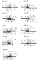
- Figure 1 shows a cross section through a simple Nozzle made in the penetration process of two pieces of textile.
- fabrics, knitted fabrics and non-woven fabrics are called textiles.
- Such Connection is with a device 1 for connecting Textiles 2.2 'made.
- the device 1 comprises a Application means 3, which comprises at least one opening 4.
- a fluid connection material 5 in is via the opening 4 the two or more, at least partially superimposed and essentially flat textile sections 6.6 ', 6' 'can be brought.
- the application means 3 is according to the invention to bring this opening 4 close to a surface of the textiles 2,2 ', but not for piercing of these textiles.
- the application means 3 has the shape of a simple nozzle, the opening 4 close to brought the outside of such a textile section 6 has been.
- Figure 1A represents the simplest of all possible in principle Connections.
- Such a connection of two textiles 2.2 ', each of which a section of textile 6.6' straight and lying flat on top of each other, can be or penetration strand processes.
- the strand process is preferred because it with these, the textile edges 10 are practically complete to cover or to grasp with connecting material 5, so that a "rising”, e.g. the formation of "running stitches” or "fraying" of the textiles is prevented.
- FIG. 1B and 1C is also a simple, seam-like Connection shown, but only the fluid connection material and not the application agent 3 penetrates individual textile sections 6,6 ', 6' 'or also 6' ''.
- the foremost tip 7 of the applicator 3 is also formed here as a frustoconical nozzle 8, the Opening 4 on the flattened surface 9 of the truncated cone 8 opens.
- This schematic representation shows the connection material 5 with a round cross section.
- the connecting material 5 - depending on the applied Quantity - also have a flattened cross-section; this will usually be the normal case (see Fig. 1A). From these representations it is also not yet clear whether it is a continuous connection or not; both are possible (see also FIG. 7A).
- Figure 1D represents a triple connection in which the to be connected textile sections 6, 6 'and the application agent 3 - not once as in FIGS. 1A to 1C - but were moved three times against each other. Care was taken that the two edge connections just the textile edge 10.10 'completely surround, which is achieved that the fabric of the textiles cannot "open". preferably, become the edge connections for such purposes established as a continuous connection (see FIG. 7B, below).
- the middle connection - it can do more than one connection include - can be continuous or punctiform (see FIG. 7B, above). That kind of connection is very suitable for joining technical fabrics, such as. for the production of sacks: the filling material and the stress caused by this can loosen the extremely stressed connection or a so-called Do not cause "peeling" of the two textile sections 6, 6 '.
- Figure 2 shows a cross section through one with a double Nozzle 11 produced in the penetration process of three pieces of textile 2.2 ', 2' ', one being double Connection is shown.
- a double nozzle 11 or a triple or multiple nozzle (not shown)
- one such a connection can withstand extreme tensile loads and is suitable e.g. for fastening carrier pieces on backpacks.
- FIG 3 shows a cross section through a simple Nozzle 8 connection made in the penetration process of two textile sections 6, 6 ', a simple one Ring connection is shown.
- a connection is achieved by first connecting material 5 pressed into the textile sections to be joined becomes. Before the connection material has hardened 5 or before cooling the hot melt adhesive is a second Medium, a so-called auxiliary fluid 12 in the center of the connection material point pressed so that the connecting material 5 is displaced from there. Then you leave the connecting material 5 solidify, or the hot melt adhesive cooling down; what remains is an annular connection (cf. 7C).
- the viscosity of the connecting material used can be rather thin (only one piece of textile 2 folded over, see. 3A) or thicker connections (both Textile pieces 2,2 'folded, cf. 3B).
- Figure 4 shows a cross section through a simple Nozzle 8 connection made in the penetration process of two pieces of textile 2.2 '.
- a simple, continuous zigzag connection see Fig. 4A and 7D
- a Opening 4 comprises and designed as a frustoconical nozzle 8 is in an oscillating manner transverse to the relative direction of travel of the textiles 2, 2 'to be joined and the Nozzle 8 moves.
- the lateral deflection became straight chosen so large that the nozzle is between the two Edge areas of the textiles 2,2 'moved.
- Fig. 4B see also Fig. 7E
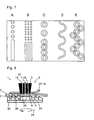
- Figure 7 shows different embodiments of seam-like Connections resulting from the use of a Device 1 in the penetration method (see. Fig. 7A to 7E) result.
- the ejection of an auxiliary fluid 12 is for the Making Connections As Shown in Figures 7C and 7E prefers.
- the device 1 preferably a work surface 23 for Placing textile parts to be connected 6,6 '... and one Means of transport 24 - for transporting the textiles opposite the working surface 23 and / or the application means 3.
- Such means of transport 24 can e.g. as a slide valve 24 ' (see FIGS. 8 and 9) or as a conveyor belt 24 ′′ (see FIG. 10 and 11).
- the application means 3 is preferably opposite the work surface 23 and / or the means of transport 24 moveable.
- Simpler embodiments of the device according to the invention 1 have an application means 3, which essentially across the direction of transport of the textiles to be joined is mobile. But it can also be a - preferably in a certain distance from the textiles to be connected 2,2 '- freely movable application means 3 can be provided, with whatever pattern to connect the textiles can be produced.
- an X / Y slide or - Table like the one connected to a computer Plotters or printers are suitable according to the corresponding Modification.
- at least one preparation agent is also preferred 22 and a solidifying agent 17 with the Application means 3 moved together.
- Figure 8 shows a vertical section through a first embodiment the device 1 for use according to the penetration point method.
- the substance, i.e. the ones to be connected Textiles are 2,2 '- as in the prior art known sewing - between a presser foot 25 and a Means of transport 24 used pushers 24 'of a device 1 introduced.
- the presser foot that acts as a pusher 16 25 comprises an application agent 3 and a solidifying agent.
- a connecting material 5 preferably a liquid hot melt adhesive, over which as a nozzle designed application means 3 delivered to the textiles:
- a metered amount 26 of the hot melt adhesive is in the textiles 2.2 'injected.
- the application agent moves during injection 8 not what the replenishment of the liquid Hot melt adhesive simplified.
- hot melt adhesive point reaches 24 ' 26 to the position of the solidifying agent in the form of a Cooling air duct 19, where this metered amount 26 of the connecting material 5 cools down quickly and solidifies.
- several hot melt adhesive points can also be used 26 (e.g. with a multiple nozzle) side by side and also one after the other (e.g. with an array nozzle, not shown) being constructed.
- This device or this Process is particularly suitable for porous textiles and those where the visible glue dots do not interfere. So that hot melt adhesive supply line 15 and cooling air duct 19 thermally are clearly separated, is preferred between the corresponding, very solid blocks, thermal insulation 27 appropriate.
- the slide valve 24 ' is without solidifying agent drawn, however, this can - to improve the Cooling capacity - also with a cooling air system (see e.g. Fig. 9) be equipped.
- Figure 10 shows a vertical section through a second embodiment the device for use according to the penetration strand method.
- the substance i.e. the ones to be connected Textiles 2, 2 'are between a sliding block 28 and a conveyor belt used as a means of transport 24 24 '' of a device 1 introduced.
- the one acting as pusher 16 Slide block 28 preferably includes a preparatory means 22, an application agent 3 and a solidifying agent 17.
- a hot melt adhesive as a connecting material 5 is the preparation for preheating the to be joined textiles 2,2 'and the solidifying agent 17 for cooling the hot melt adhesive 5.
- the application agent 3, designed to be heatable for feeding the hot melt adhesive can also be heated with the preparation means 22 be formed together, the cooled solidifying agent 17 of these two is preferred by means of insulation 27 thermally separated.
- a Connecting material 5 preferably a liquid hot melt adhesive
- the application means 3 designed as a nozzle the textiles released: hotmelt adhesive material becomes continuous in the textiles, which are also transported continuously 2.2 'injected. This moves when injecting Application means 3 not what the subsequent delivery of the liquid Hot melt adhesive and the coolant air (other preferably oil-free gases, e.g. Nitrogen gas or Carbon dioxide are used) simplified.
- the injected hot melt strand reaches 24 '' 26 'to the position of the solidifying agent 17 in the form of a Cooling air duct 19 and / or a massive cooling block 29, where this strand cools down quickly and solidifies.
- several hot melt adhesive strands 26 ' can be built side by side.
- the transport the interconnected textiles 2, 2 ' is made by rolling 30, which are arranged laterally on the sliding block 28, supported. This device or method is suitable especially for technical fabrics and monofil filters and general for the quick production of long, straight or curved connections of textiles 2,2 '.
- Deviating from the representation in the figures can also Auxiliary fluids 12 are used, which - together with the Connection material 5 - a chemical two-component system form and - upon contact with the connecting material 5 - bring this to solidify.
- This auxiliary fluid 12 can before the connecting material 5 as a fluid preparation 22 can be used, which is a chemical precursor or "Primer” substance "the textile sections to be joined 6.6 ', 6' '... essentially impregnated and the one Solidification of the connecting material 5 causes as soon as this comes into contact with this primer substance.
- An afterthought applied to apply the connecting material 5 Auxiliary fluid 12 can - with or without radiation support, like UV light and the like - the same effect produce.
- FIG 12 shows a first embodiment of a pressure generating part 32, which in the device 1 for generating a higher pressure in the connecting material 5 is used.
- This Pressure generating part 32 pumps hot melt adhesive into a one to be produced Connection as described so far by way of example were. It can also be used to take turns Hot melt adhesive and air in the connection to be made to pump. In the second case, the air is used to to separate specific connection points and the hot Keep hot melt adhesive away from the guides as far as possible. additionally the heated air heats the textiles to be joined Fabrics on what the adhesion of the adhesive with same improved.
- the pressure generating part 32 comprises one Storage or container 20 for e.g. can be filled in as granules Melt adhesive.
- a heater 33 By means of a heater 33, the container 20 brought to a desired temperature and thus the hot melt adhesive 5 liquefied.
- a heater 33 which has one or more heating elements also includes an entire assembly, the hot melt adhesive 5 in the container 20 and the air in the assembly a desired temperature can be brought. At least in the lower one Part of the container 20, where the lines for forwarding of the hot melt adhesive 5, this is through the heating 33 liquefied so that it can be used in fluid form ready.
- This frustoconical nozzle 8 forms the application means 3 the device 1 according to the invention.
- first check valve 41 clear the way to the cylinder 38.
- a second and third Check valve 42,43 are, in particular to prevent the Inflow of air into the cylinder 38, through the resulting Suction and closed by its internal spring tension.
- Piston 37 closes the first check valve 41 under its internal spring tension. Then the Piston 37 advanced by the eccentric 36, whereby the pressure in first cylinder 38 - against the adjustable spring pressure of the second check valve 42 - is increased.
- this valve 42 opens and thus releases long hot melt adhesive in the pressure line 44 and back in the container 20 as the cylinder pressure is too high. It the result is a preselectable, essentially constant Pressure that is high enough, the third check valve 43 to open and the nozzle 8 via the nozzle line 39 to be supplied with liquid hot melt adhesive. When reaching close the front reversal point of the piston 37 all check valves that are still open (e.g. 43), whereupon the next cycle begins.
- Deviating from the previous description of the inventive Pressure generating part 32 can the assembly shown also to generate a continuous ejection of Connecting material 5 or hot melt adhesive are used, if the suction line 45 and the pressure line 44 'also be passed into the container 20. If one more more uniform delivery of the nozzles 8, 13 with hot melt adhesive if desired, three or more corresponding and coupled cylinders can be provided. So can, to carry out the penetration strand method described, through this continuous ejection of Hot melt adhesive produced from the nozzle 8, connecting material 5 and injected into the textiles 2, 2 '.
- Pressure generating part 32 can be another alternative assembly for generating a higher pressure in the Connection material 5 serve. That assembly is involved e.g. an extruder that is a motor driven one Screw conveyor and a nozzle foot for the penetration process includes (not shown). Is preferred an extruder with an attached container and an integrated Heating so that - as with the assembly of Fig. 12 - connecting material in the form of granules, powder or can also be filled and liquefied as a "monofilament". A solenoid valve also gives a liquid hot melt adhesive here clear the way to the nozzle.
- the extruder Preferably coaxial with the A compressed air chamber is arranged in the extruder, which together heatable with the extruder and also with a solenoid valve is equipped.
- the extruder nozzle lines and the compressed air chamber unite (similar to in Fig. 12) in the area of the nozzle base and open together in an opening 4 on the surface of the nozzle base or applicator 3.
- the fluid connection material 5 to be used can be used as Liquid, as a liquid-gas mixture (e.g. as Foam, spray etc.) or as a gas. If the connection material 5 is introduced in foam form, arise thereby more elastic connections between the textiles 2.2 '. Glue the contact points of the fogged fibrils together. Textile fabrics glued with foam (Fabrics, knitted fabrics, tiles) remain in the connecting region more elastic than when completely filled with a liquid Connecting material. Reach the connections thus obtained however not the same resilience.
Landscapes
- Engineering & Computer Science (AREA)
- Mechanical Engineering (AREA)
- Textile Engineering (AREA)
- Treatment Of Fiber Materials (AREA)
- Laminated Bodies (AREA)
- Professional, Industrial, Or Sporting Protective Garments (AREA)
- Ropes Or Cables (AREA)
Description
- Fig. 1
- einen Querschnitt durch eine mit einer einfachen Düse
im Durchdringungs-Verfahren hergestellten Verbindung
von zwei Textilstücken, wobei:
- Fig. 1A
- die im Prinzip einfachste Verbindung,
- Fig. 1B,1C
- eine weitere, einfache Verbindung, und
- Fig. 1D
- eine dreifache Verbindung, darstellt;
- Fig. 2
- einen Querschnitt durch eine mit einer doppelten Düse im Durchdringungs-Verfahren hergestellten Verbindung von drei Textilstücken, wobei eine doppelte Verbindung dargestellt ist;
- Fig. 3
- einen Querschnitt durch eine mit einer einfachen Düse im Durchdringungs-Verfahren hergestellten Verbindung von zwei Textilstücken, wobei eine einfache Ringverbindung dargestellt ist;
- Fig. 4
- einen Querschnitt durch eine mit einer einfachen Düse
im Durchdringungs-Verfahren hergestellten Verbindung
von zwei Textilstücken, wobei:
- Fig. 4A
- eine einfache Zick-Zack-Verbindung, und
- Fig. 4B
- eine einfache Zick-Zack-Ringverbindung darstellt;
- Fig. 7
- Ausführungsformen von nahtähnlichen Verbindungen:
- Fig. 7A
- einfach, im Punkt- bzw. Strang-Verfahren;
- Fig. 7B
- dreifach, im Punkt- bzw. Strang-Verfahren;
- Fig. 7C
- einfach, im Durchdringungs-Punkt-Verfahren mit Hilfsfluidausstoss;
- Fig. 7D
- einfach, im Strang-Zick-Zack-Verfahren;
- Fig. 7E
- einfach, im Durchdringungs-Punkt-Verfahren mit Hilfsfluidausstoss, im Zick-Zack-Muster;
- Fig. 8
- einen Vertikalschnitt durch eine erste Ausführungsform der Vorrichtung zur Verwendung nach dem Durchdringungs-Punkt-Verfahren;
- Fig. 10
- einen Vertikalschnitt durch eine zweite Ausführungsform der Vorrichtung zur Verwendung nach dem Durchdringungs-Strang-Verfahren;
- Fig. 12
- eine erste Ausführungsform eines Druckerzeugungsteils.
Vorteile der erfindungsgemässen Vorrichtung bzw. des erfindungsgemässen Verfahrens umfassen:
- Grundsätzlich wird auf das Verwenden von den die Textilien durchdringenden Nadeln verzichtet. Dies ermöglicht eine wesentlich schonendere Verbindung dieser Textilien miteinander: Nähgutschäden durch z.B. beim Transport zu stark gepresstes Nähgut oder gar durch beschädigte Nadelspitzen können nicht entstehen.
- Eine Wellenbildung in den Textilien, wie sie im Stand
der Näh-Technik als "Nahtkräuseln" bekannt ist, kann
vermieden werden:
- "Transportkräuseln" tritt auf, wenn beim Stofftransport die obere und untere Nähgutlage gegeneinander verschoben werden: Die untere Lage wird z.B. durch den Stoffschieber weiter geschoben, während die obere Lage vom Stoffdrücker (Nähfuss) zurückgehalten wird. Dies kann nicht auftreten, weil die erfindungsgemässe Vorrichtung 1 Rollen 30 und ein Transportband 24'' umfasst (vgl. Fig. 10), welche beide zu verbindenden Textilien 2,2' gleichmässig transportieren.
- "Verdrängungskräuseln" entsteht beim Einstich von Nadel und Faden in das Nähgut, weil dadurch Kett- und Schussfäden verdrängt werden. Dies kann nicht auftreten, weil das erfindungsgemässe Verfahren auf die Verwendung von Nadel und Faden verzichtet.
- "Spannungskräuseln" kann durch eine zu hohe Fadenspannung beim Nähen sowie ein ungünstiges Dehnungsverhalten der Nähzwirne verursacht werden. Dies kann nicht auftreten, weil die erfindungsgemässe Vorrichtung 1 Rollen 30 und ein Transportband 24'' umfasst (vgl. Fig. 10), welche beide zu verbindenden Textilien 2,2' gleichmässig transportieren. Dies kann nicht auftreten, weil das erfindungsgemässe Verfahren konsequent auf die Verwendung von Faden verzichtet.
- Ein gezielter Mehrtransport (Mehrweite der unteren oder oberen Stofflage) kann dank unabhängig voneinander ansteuerbarer Transportmittel 24 erzielt werden (vgl. Fig. 10).
- Die Vorrichtung kann in bestehende Nähmaschinen integriert werden, so dass deren Hilfsmittel, wie z.B. der Transportmechanismus (z.B. Stoffschieber), der Stoffdrücker (Nähfuss) und praktisch alle bekannten Nähgutführungen übernommen bzw. adaptiert werden können.
- Dank der erfindungsgemässen Verbindung wird auch bei grosser Zugbelastung derselben eine Bildung von Gewebeschäden (z.B. "Laufmaschen") verhindert, auch wenn bei solchen Verbindungen technischer Gewebe auf eine Überlappung der zu verbindenden Textilienabschnitte 6,6' ... verzichtet werden muss.
Claims (12)
- Vorrichtung (1) zum Verbinden von Textilien (2,2') mit einem Appliziermittel (3), welches zumindest eine Öffnung (4) umfasst, über die ein fluides Verbindungsmaterial (5) zumindest teilweise zwischen zwei oder mehrere, zumindest teilweise aufeinandergelegte und im Wesentlichen flächige Textilienabschnitte (6,6',6''...) bringbar ist, wobei das Appliziermittel (3) zum Heranführen dieser Öffnung (4) in die Nähe einer Oberfläche der Textilien (2,2'), jedoch nicht zum Durchstossen dieser Textilien ausgebildet ist,
dadurch gekennzeichnet, dassdie Vorrichtung (1) ein Druckerzeugungsteil (32) zur Erhöhung des Druckes des fluiden Verbindungsmaterials beim Ausstossen aus der zumindest einen Öffnung umfasst, mit dessen Hilfe das Verbindungsmaterial (5) in Textilien (2,2') hinein und durch diese hindurch pressbar ist unddas Appliziermittel (3) bzw. die Öffnung (4) auf die Aussenseite von solchen Textilienabschnitten (6,6',6''...) bringbar ausgebildet ist. - Vorrichtung nach Anspruch 1, dadurch gekennzeichnet, dass das Druckerzeugungsteil (32) zum Erzeugen eines Druckes in einem Hilfsfluid (12) ausgebildet ist.
- Vorrichtung nach Anspruch 1 oder 2, dadurch gekennzeichnet, dass sie Vorbereitungsmittel (22) zum Vorbereiten, insbesondere zum Vorwärmen, von Textilienabschnitten (6,6',6''...) umfasst.
- Vorrichtung nach einem der vorstehenden Ansprüche, dadurch gekennzeichnet, dass sie Verfestigungsmittel (17) zum Verfestigen, insbesondere zum Abkühlen, des eingebrachten Verbindungsmaterials (5) umfasst.
- Vorrichtung nach einem der vorstehenden Ansprüche, welche eine Arbeitsfläche (23) zum Auflegen von zu verbindenden Textilienabschnitten (6,6',6''...) umfasst, dadurch gekennzeichnet, dass sie ein Transportmittel (24) - zum Transportieren der Textilien gegenüber der Arbeitsfläche (23) und/oder dem Appliziermittel (3) - umfasst.
- Vorrichtung nach Anspruch 5, dadurch gekennzeichnet, dass das Appliziermittel (3) gegenüber der Arbeitsfläche (23) und/oder dem Transportmittel (24) beweglich ausgebildet ist.
- Verfahren zum Verbinden von Textilien (2,2') mit einer Vorrichtung (1), welche ein Appliziermittel (3) mit zumindest einer Öffnung (4) umfasst, bei dem ein fluides Verbindungsmaterial (5) zumindest teilweise zwischen zwei oder mehrere, zumindest teilweise aufeinandergelegte und im Wesentlichen flächige Textilienabschnitte (6,6'6,6''...) gebracht wird, wobei das Appliziermittel (3) mit dieser Öffnung (4) in die Nähe einer Oberfläche der Textilien (2,2') herangeführt wird, ohne diese Textilien zu durchstossen,
dadurch gekennzeichnet, dassmit einem Druckerzeugungsteil (32) zur Erhöhung des Druckes des fluiden Verbindungsmaterials beim Ausstossen aus der zumindest einen Öffnung das Verbindungsmaterial (5) in Textilien (2,2') hinein und durch diese hindurch gepresst wird unddas Appliziermittel (3) bzw. die Öffnung (4) auf die Aussenseite von solchen Textilienabschnitten gebracht wird. - Verfahren nach Anspruch 7, gekennzeichnet durch die folgenden Arbeitsschritte:Bereitlegen von Textilmaterialien (2,2') zwischen einem mit einem Appliziermittel (3) ausgerüsteten Nähfuss (25) und einem als Stoffschieber (24') ausgebildeten Transportmittel (24);Einspritzen bzw. Durchspritzen einer ersten dosierten Menge (26) von Verbindungsmaterial (5) in bzw. durch das Textilmaterial (2,2');Ausführen eines Hubes mit dem Stoffschieber (24') und Positionieren des ersten eingespritzten Verbindungsmaterial-Punktes (26) an dem Verfestigungsmittel (17);Verfestigen des ersten eingespritzten Verbindungsmaterial-Punktes (26) und Einspritzen einer zweiten dosierten Menge (26) von Verbindungsmaterial (5) in das Textilmaterial (2,2').
- Verfahren nach Anspruch 7, gekennzeichnet durch die folgenden Arbeitsschritte:Bereitlegen von Textilmaterialien (2,2') zwischen einem mit einem Verfestigungsmittel (17) ausgerüsteten Gleitblock (28) und einem mit einem Verfestigungsmittel (17) ausgerüsteten und bandförmigen Transportmittel (24'');Einspritzen bzw. Durchspritzen von Verbindungsmaterial (5) in das Textilmaterial (2) sowie Transportieren der Textilmaterialien (2,2') und Verfestigen des entstehenden Verbindungsmaterial-Bandes (26') in kontinuierlicher Weise.
- Verfahren nach Anspruch 9, dadurch gekennzeichnet, dass der Gleitblock (28) mit dem Appliziermittel (3) - zum Erzeugen einer von einer Geraden abweichenden Verbindung - gegenüber dem Transportmittel (24) bewegt wird.
- Verfahren nach einem der Ansprüche 7 bis 10, dadurch gekennzeichnet, dass - abwechselnd mit dem Einbringen des Verbindungsmaterials (5) - ein Hilfsfluid (12) durch die gleiche Öffnung (4) wie das Verbindungsmaterial (5) gepresst wird, so dass Portionen (26) des Verbindungsmaterials eingebracht werden.
- Verfahren nach Anspruch 11, dadurch gekennzeichnet, dass mit dem Hilfsfluid (12) zumindest ein Teil der Verbindungsmaterial-Portionen (26) aus der Textilverbindung entfernt werden.
Applications Claiming Priority (3)
| Application Number | Priority Date | Filing Date | Title |
|---|---|---|---|
| CH10422000 | 2000-05-24 | ||
| CH104200 | 2000-05-24 | ||
| PCT/CH2001/000322 WO2001089812A1 (de) | 2000-05-24 | 2001-05-23 | Verbindung von textilien |
Publications (2)
| Publication Number | Publication Date |
|---|---|
| EP1283774A1 EP1283774A1 (de) | 2003-02-19 |
| EP1283774B1 true EP1283774B1 (de) | 2004-09-29 |
Family
ID=4554361
Family Applications (1)
| Application Number | Title | Priority Date | Filing Date |
|---|---|---|---|
| EP01931306A Expired - Lifetime EP1283774B1 (de) | 2000-05-24 | 2001-05-23 | Verbindung von textilien |
Country Status (5)
| Country | Link |
|---|---|
| EP (1) | EP1283774B1 (de) |
| AT (1) | ATE277748T1 (de) |
| AU (1) | AU2001258133A1 (de) |
| DE (1) | DE50103890D1 (de) |
| WO (1) | WO2001089812A1 (de) |
Cited By (1)
| Publication number | Priority date | Publication date | Assignee | Title |
|---|---|---|---|---|
| WO2021183003A3 (ru) * | 2020-03-03 | 2021-11-04 | Dubrovsky Arkady Veniaminovich | Швейная машина |
Families Citing this family (9)
| Publication number | Priority date | Publication date | Assignee | Title |
|---|---|---|---|---|
| JP5251561B2 (ja) * | 2009-02-04 | 2013-07-31 | ブラザー工業株式会社 | 布接着装置及び接着プログラム |
| JP5251560B2 (ja) * | 2009-02-04 | 2013-07-31 | ブラザー工業株式会社 | 布接着装置 |
| JP2010222763A (ja) * | 2009-03-25 | 2010-10-07 | Brother Ind Ltd | 布接着装置、及び圧力制御プログラム |
| JP5177046B2 (ja) * | 2009-03-25 | 2013-04-03 | ブラザー工業株式会社 | 布接着装置 |
| EP2233277B1 (de) * | 2009-03-25 | 2014-07-16 | Brother Kogyo Kabushiki Kaisha | Vorrichtung zum Verbinden von Stoff |
| JP2010222762A (ja) | 2009-03-25 | 2010-10-07 | Brother Ind Ltd | 布接着装置 |
| JP5434263B2 (ja) * | 2009-05-22 | 2014-03-05 | ブラザー工業株式会社 | 布接着装置 |
| JP5262999B2 (ja) * | 2009-05-28 | 2013-08-14 | ブラザー工業株式会社 | 布接着装置 |
| JP6394186B2 (ja) * | 2014-08-28 | 2018-09-26 | ブラザー工業株式会社 | 布接着装置 |
Family Cites Families (5)
| Publication number | Priority date | Publication date | Assignee | Title |
|---|---|---|---|---|
| US3295493A (en) * | 1963-02-26 | 1967-01-03 | Yamamoto Shokichi | Automatic apparatus combined with industrial sewing machine for filling seam of a synthetic resin film |
| US3785898A (en) * | 1972-01-14 | 1974-01-15 | Gerber Garment Technology Inc | Apparatus for producing seamed articles from sheet material |
| DE3342394C2 (de) * | 1983-11-24 | 1986-03-27 | Dynamit Nobel Ag, 5210 Troisdorf | Vorrichtung zum Quellverschweißen von Kunststoffbahnen |
| AU2879395A (en) * | 1994-06-30 | 1996-01-25 | Gerd Ebert | Method of assembling products and sewing machine needles and sewing thread for carrying out this method |
| FR2737954B1 (fr) * | 1995-08-24 | 1998-01-23 | Michel Bordage | Procede et dispositif pour assembler deux pieces d'etoffe ou analogue, et article, notamment vestimentaire, ainsi obtenu |
-
2001
- 2001-05-23 AT AT01931306T patent/ATE277748T1/de not_active IP Right Cessation
- 2001-05-23 WO PCT/CH2001/000322 patent/WO2001089812A1/de not_active Ceased
- 2001-05-23 EP EP01931306A patent/EP1283774B1/de not_active Expired - Lifetime
- 2001-05-23 AU AU2001258133A patent/AU2001258133A1/en not_active Abandoned
- 2001-05-23 DE DE50103890T patent/DE50103890D1/de not_active Expired - Fee Related
Cited By (1)
| Publication number | Priority date | Publication date | Assignee | Title |
|---|---|---|---|---|
| WO2021183003A3 (ru) * | 2020-03-03 | 2021-11-04 | Dubrovsky Arkady Veniaminovich | Швейная машина |
Also Published As
| Publication number | Publication date |
|---|---|
| DE50103890D1 (de) | 2004-11-04 |
| AU2001258133A1 (en) | 2001-12-03 |
| ATE277748T1 (de) | 2004-10-15 |
| WO2001089812A1 (de) | 2001-11-29 |
| EP1283774A1 (de) | 2003-02-19 |
Similar Documents
| Publication | Publication Date | Title |
|---|---|---|
| DE69625076T2 (de) | Verfahren und vorrichtung zum verbinden von stoffstücken oder dgl. und so hergestellter artikel wie bekleidungsstück | |
| DE3942957C2 (de) | Vorrichtung zum Einbringen eines dosierten Gasvolumens in einen mit einer Kunststoffschmelze gefüllten Formhohlraum einer Spritzform | |
| DE2031466A1 (de) | Tufting Maschine | |
| DE3502608A1 (de) | Verfahren und vorrichtung zum verkleben von textilen flaechengebilden | |
| DE920980C (de) | Verfahren und Vorrichtung zum Herauspressen von fadenbildenden Materialien | |
| DE2727877A1 (de) | Tuftingmaschine mit waehlbaren nadeln | |
| DE2933270A1 (de) | Naehverfahren und -maschine | |
| DE19503971A1 (de) | Verfahren und Vorrichtung zur Herstellung eines Saatbands | |
| EP1283774A1 (de) | Verbindung von textilien | |
| DE2635113A1 (de) | Eingriffselement fuer einen reissverschluss sowie verfahren und vorrichtung zur herstellung eines befestigungselementes und einer reihe von befestigungselementen fuer einen reissverschluss | |
| EP1199108B1 (de) | Düsenanordnung, Auftragsvorrichtung sowie Auftragsverfahren | |
| DE69804958T2 (de) | Verfahren und vorrichtung zum füllen von tuben | |
| DE102005011059B3 (de) | Verfahren und Vorrichtung zur Herstellung von querelastischen mehrschichtigen Materialbahnen | |
| DE3132022C2 (de) | ||
| DE3448316C2 (de) | ||
| DE2640132C3 (de) | Vorrichtung zum Bemustern und Färben von flächigem Textilgut o.dgl | |
| DE1925692C3 (de) | Verfahren und Vorrichtung zur Herstellung eines Polstoffes | |
| DE4102877A1 (de) | Vorrichtung zum herstellen und stapeln von beuteln | |
| EP1793036B1 (de) | Verfahren zur Herstellung flüssigkeitsundurchlässiger Papiermaschinenbänder sowie Beschichtungsvorrichtung hierfür | |
| DE1704247A1 (de) | Verfahren zum Verbinden von Gegenstaenden durch Kunststoff und Vorrichtung zu seiner Ausfuehrung | |
| DE2303796C3 (de) | Verfahren und Anlage zur Herstellung einer ReiSverschluBgliederreihe aus thermoplastischem Kunststoff mit angeschlossenem Tragband | |
| DE685347C (de) | Vorrichtung an Naehmaschinen zum Einnaehen elastischer Faeden in Stoffstuecke | |
| DE1485470A1 (de) | Vorrichtung und Verfahren zum Herstellen von Florgeweben | |
| DE2323660C3 (de) | Vorrichtung zum automatischen Abmessen und Abgeben von gleichen Mengen eines trockenen Pulvers | |
| DE2017792A1 (de) | Bettwäschestück mit doppelt liegenden Stoffbahnen und Verfahren zu seiner Herstellung sowie Vorrichtung zur Ausführung des Verfahrens |
Legal Events
| Date | Code | Title | Description |
|---|---|---|---|
| PUAI | Public reference made under article 153(3) epc to a published international application that has entered the european phase |
Free format text: ORIGINAL CODE: 0009012 |
|
| 17P | Request for examination filed |
Effective date: 20021026 |
|
| AK | Designated contracting states |
Designated state(s): AT BE CH CY DE DK ES FI FR GB GR IE IT LI LU MC NL PT SE TR |
|
| AX | Request for extension of the european patent |
Extension state: AL LT LV MK RO SI |
|
| 17Q | First examination report despatched |
Effective date: 20030123 |
|
| GRAP | Despatch of communication of intention to grant a patent |
Free format text: ORIGINAL CODE: EPIDOSNIGR1 |
|
| GRAS | Grant fee paid |
Free format text: ORIGINAL CODE: EPIDOSNIGR3 |
|
| GRAA | (expected) grant |
Free format text: ORIGINAL CODE: 0009210 |
|
| AK | Designated contracting states |
Kind code of ref document: B1 Designated state(s): AT BE CH CY DE DK ES FI FR GB GR IE IT LI LU MC NL PT SE TR |
|
| PG25 | Lapsed in a contracting state [announced via postgrant information from national office to epo] |
Ref country code: IE Free format text: LAPSE BECAUSE OF FAILURE TO SUBMIT A TRANSLATION OF THE DESCRIPTION OR TO PAY THE FEE WITHIN THE PRESCRIBED TIME-LIMIT Effective date: 20040929 Ref country code: TR Free format text: LAPSE BECAUSE OF FAILURE TO SUBMIT A TRANSLATION OF THE DESCRIPTION OR TO PAY THE FEE WITHIN THE PRESCRIBED TIME-LIMIT Effective date: 20040929 Ref country code: FR Free format text: LAPSE BECAUSE OF FAILURE TO SUBMIT A TRANSLATION OF THE DESCRIPTION OR TO PAY THE FEE WITHIN THE PRESCRIBED TIME-LIMIT Effective date: 20040929 Ref country code: FI Free format text: LAPSE BECAUSE OF FAILURE TO SUBMIT A TRANSLATION OF THE DESCRIPTION OR TO PAY THE FEE WITHIN THE PRESCRIBED TIME-LIMIT Effective date: 20040929 Ref country code: GB Free format text: LAPSE BECAUSE OF FAILURE TO SUBMIT A TRANSLATION OF THE DESCRIPTION OR TO PAY THE FEE WITHIN THE PRESCRIBED TIME-LIMIT Effective date: 20040929 Ref country code: NL Free format text: LAPSE BECAUSE OF FAILURE TO SUBMIT A TRANSLATION OF THE DESCRIPTION OR TO PAY THE FEE WITHIN THE PRESCRIBED TIME-LIMIT Effective date: 20040929 |
|
| REG | Reference to a national code |
Ref country code: GB Ref legal event code: FG4D Free format text: NOT ENGLISH |
|
| REG | Reference to a national code |
Ref country code: CH Ref legal event code: EP |
|
| REG | Reference to a national code |
Ref country code: IE Ref legal event code: FG4D Free format text: GERMAN |
|
| REF | Corresponds to: |
Ref document number: 50103890 Country of ref document: DE Date of ref document: 20041104 Kind code of ref document: P |
|
| PG25 | Lapsed in a contracting state [announced via postgrant information from national office to epo] |
Ref country code: SE Free format text: LAPSE BECAUSE OF FAILURE TO SUBMIT A TRANSLATION OF THE DESCRIPTION OR TO PAY THE FEE WITHIN THE PRESCRIBED TIME-LIMIT Effective date: 20041229 Ref country code: DK Free format text: LAPSE BECAUSE OF FAILURE TO SUBMIT A TRANSLATION OF THE DESCRIPTION OR TO PAY THE FEE WITHIN THE PRESCRIBED TIME-LIMIT Effective date: 20041229 Ref country code: GR Free format text: LAPSE BECAUSE OF FAILURE TO SUBMIT A TRANSLATION OF THE DESCRIPTION OR TO PAY THE FEE WITHIN THE PRESCRIBED TIME-LIMIT Effective date: 20041229 |
|
| REG | Reference to a national code |
Ref country code: CH Ref legal event code: NV Representative=s name: R. A. EGLI & CO. PATENTANWAELTE |
|
| PG25 | Lapsed in a contracting state [announced via postgrant information from national office to epo] |
Ref country code: ES Free format text: LAPSE BECAUSE OF FAILURE TO SUBMIT A TRANSLATION OF THE DESCRIPTION OR TO PAY THE FEE WITHIN THE PRESCRIBED TIME-LIMIT Effective date: 20050109 |
|
| LTIE | Lt: invalidation of european patent or patent extension |
Effective date: 20040929 |
|
| NLV1 | Nl: lapsed or annulled due to failure to fulfill the requirements of art. 29p and 29m of the patents act | ||
| REG | Reference to a national code |
Ref country code: IE Ref legal event code: FD4D |
|
| GBV | Gb: ep patent (uk) treated as always having been void in accordance with gb section 77(7)/1977 [no translation filed] |
Effective date: 20040929 |
|
| PG25 | Lapsed in a contracting state [announced via postgrant information from national office to epo] |
Ref country code: LU Free format text: LAPSE BECAUSE OF NON-PAYMENT OF DUE FEES Effective date: 20050523 Ref country code: CY Free format text: LAPSE BECAUSE OF FAILURE TO SUBMIT A TRANSLATION OF THE DESCRIPTION OR TO PAY THE FEE WITHIN THE PRESCRIBED TIME-LIMIT Effective date: 20050523 |
|
| PG25 | Lapsed in a contracting state [announced via postgrant information from national office to epo] |
Ref country code: BE Free format text: LAPSE BECAUSE OF NON-PAYMENT OF DUE FEES Effective date: 20050531 Ref country code: MC Free format text: LAPSE BECAUSE OF NON-PAYMENT OF DUE FEES Effective date: 20050531 |
|
| PLBE | No opposition filed within time limit |
Free format text: ORIGINAL CODE: 0009261 |
|
| STAA | Information on the status of an ep patent application or granted ep patent |
Free format text: STATUS: NO OPPOSITION FILED WITHIN TIME LIMIT |
|
| 26N | No opposition filed |
Effective date: 20050630 |
|
| EN | Fr: translation not filed | ||
| BERE | Be: lapsed |
Owner name: SCHAEPPER ENGINEERING GMBH Effective date: 20050531 |
|
| PGFP | Annual fee paid to national office [announced via postgrant information from national office to epo] |
Ref country code: AT Payment date: 20070515 Year of fee payment: 7 |
|
| PGFP | Annual fee paid to national office [announced via postgrant information from national office to epo] |
Ref country code: DE Payment date: 20070522 Year of fee payment: 7 |
|
| PGFP | Annual fee paid to national office [announced via postgrant information from national office to epo] |
Ref country code: CH Payment date: 20070827 Year of fee payment: 7 |
|
| BERE | Be: lapsed |
Owner name: *SCHAEPPER ENGINEERING G.M.B.H. Effective date: 20050531 |
|
| PG25 | Lapsed in a contracting state [announced via postgrant information from national office to epo] |
Ref country code: PT Free format text: LAPSE BECAUSE OF NON-PAYMENT OF DUE FEES Effective date: 20050228 |
|
| PGFP | Annual fee paid to national office [announced via postgrant information from national office to epo] |
Ref country code: IT Payment date: 20070515 Year of fee payment: 7 |
|
| REG | Reference to a national code |
Ref country code: CH Ref legal event code: PL |
|
| PG25 | Lapsed in a contracting state [announced via postgrant information from national office to epo] |
Ref country code: CH Free format text: LAPSE BECAUSE OF NON-PAYMENT OF DUE FEES Effective date: 20080531 Ref country code: LI Free format text: LAPSE BECAUSE OF NON-PAYMENT OF DUE FEES Effective date: 20080531 |
|
| PG25 | Lapsed in a contracting state [announced via postgrant information from national office to epo] |
Ref country code: AT Free format text: LAPSE BECAUSE OF NON-PAYMENT OF DUE FEES Effective date: 20080523 |
|
| PG25 | Lapsed in a contracting state [announced via postgrant information from national office to epo] |
Ref country code: DE Free format text: LAPSE BECAUSE OF NON-PAYMENT OF DUE FEES Effective date: 20081202 |
|
| PG25 | Lapsed in a contracting state [announced via postgrant information from national office to epo] |
Ref country code: IT Free format text: LAPSE BECAUSE OF NON-PAYMENT OF DUE FEES Effective date: 20080523 |