EP1281479A2 - Spannelement mit hydraulisch betätigten Schiebern - Google Patents
Spannelement mit hydraulisch betätigten Schiebern Download PDFInfo
- Publication number
- EP1281479A2 EP1281479A2 EP02102029A EP02102029A EP1281479A2 EP 1281479 A2 EP1281479 A2 EP 1281479A2 EP 02102029 A EP02102029 A EP 02102029A EP 02102029 A EP02102029 A EP 02102029A EP 1281479 A2 EP1281479 A2 EP 1281479A2
- Authority
- EP
- European Patent Office
- Prior art keywords
- clamping
- clamping element
- element according
- workpiece
- slide
- Prior art date
- Legal status (The legal status is an assumption and is not a legal conclusion. Google has not performed a legal analysis and makes no representation as to the accuracy of the status listed.)
- Granted
Links
Images
Classifications
-
- B—PERFORMING OPERATIONS; TRANSPORTING
- B25—HAND TOOLS; PORTABLE POWER-DRIVEN TOOLS; MANIPULATORS
- B25B—TOOLS OR BENCH DEVICES NOT OTHERWISE PROVIDED FOR, FOR FASTENING, CONNECTING, DISENGAGING, OR HOLDING
- B25B1/00—Vices
- B25B1/06—Arrangements for positively actuating jaws
- B25B1/18—Arrangements for positively actuating jaws motor driven, e.g. with fluid drive, with or without provision for manual actuation
-
- B—PERFORMING OPERATIONS; TRANSPORTING
- B25—HAND TOOLS; PORTABLE POWER-DRIVEN TOOLS; MANIPULATORS
- B25B—TOOLS OR BENCH DEVICES NOT OTHERWISE PROVIDED FOR, FOR FASTENING, CONNECTING, DISENGAGING, OR HOLDING
- B25B5/00—Clamps
- B25B5/06—Arrangements for positively actuating jaws
- B25B5/061—Arrangements for positively actuating jaws with fluid drive
Definitions
- Clamping element with two parallel guided clamping jaws for position-flexible Clamping of workpieces, in particular for supporting the workpieces in their predetermined clamping position at any point.
- clamping elements For clamping workpieces clamping elements are used, the Position the workpiece in position. Labile and longer workpieces require more Clamping units, by means of which it determines position at all critical points get supported. These clamping elements must be applied to the workpiece after this is already stated in its position. The introduction such clamping units must be made so that the workpiece at the points which the clamping units come to rest, is not distorted or deformed. This high demands are placed on such clamping elements.
- Clamping elements are usually operated hydraulically. The hydraulic pressure is introduced so that the clamping element his jaws toward each other or moved away from each other. Disagreements in the hydraulics or in the Friction surfaces that affect the moving parts can easily become too Lead tensions of the workpieces.
- labile places to the most diverse workpieces be stabilized with one element.
- the invention is thus a clamping element with two flexibly movable, parallel arranged sliders on which the jaws are placed. At the Clamping put the jaws posotionsix pliers like the Workpiece. Thus, two equally large opposing contact forces act at two opposite points on the workpiece. These two Touching forces are similar in their effect according to the principle of action Reaction to and thus do not lead to deformation or tension of the Workpiece.
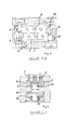
- the plunger 9 u. 10 are in the piston plates 15; 16 arranged so that the from them outgoing force directly on the end faces 17; 18, the slider 2; 3 is initiated in this.
- the sliders are running smooth and even in their guide surfaces and transmit the power directly to the clamping point 19 and the workpiece 20 without this deform.
- the result is the workpiece 20 equal oppositely directed forces after the principle action equal reaction.
- the resulting load moment - Clamping force x lever arm a - is determined by the guide surfaces within the recess 4; 5 recorded, wherein the recess 4; 5 with their guide surfaces in about the housing length corresponds. These relatively large guide surfaces help that the frictional forces are kept as low as possible.
- a piston 22 for setting intended In the housing 1 is below the recess 4, 5 a piston 22 for setting intended.
- This piston 22 is driven separately. He is at his head end provided with a dovetail-shaped wedge piece 23, the exact in an im Slider 2, 3 recessed recess 6 is fitted, in such a way that in relaxed state, the slider 2; 3 on the wedge piece 23 without contact slide past. The leadership of the slide takes place at the contact surfaces in the Recesses 6.
- the piston 22 is acted upon by the hydraulic connection 25. Its return takes place by means of associated disc springs 24. Die If necessary, provision can also be made hydraulically.
- the piston 22 is acted upon by hydraulic connection 25.
- This piston will thereby pulled down into the housing 1.
- the trained as a wedge piece 23 head is pulled down in the recess 6 and presses on the Side surfaces of the recess 6.
- the Clamping element is set so that it is independent of external forces as well with pressure drop in the hydraulics remains in its position and thus acts self-locking, this is due to the configuration of the wedge piece 23rd causes.
Landscapes
- Engineering & Computer Science (AREA)
- Mechanical Engineering (AREA)
- Jigs For Machine Tools (AREA)
Abstract
Description
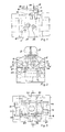
- Fig. 1
- zeigt die Frontansicht
- Fig. 2
- zeigt die Seitenansicht
- Fig. 3
- zeigt eine Draufsicht
- Fig. 4
- zeigt den Schnitt B-B
- Fig. 5
- zeigt den Schnitt A-A
| 1 | Gehäuse |
| 2 | Schieber |
| 3 | Schieber |
| 4 | Aussparung |
| 5 | Aussparung |
| 6 | Ausnehmung |
| 7 | Spannbacken |
| 8 | Spannbacken |
| 9 | Plungerkolben spannen |
| 10 | Plungerkolben spannen |
| 11 | Plungerkolben entspannen |
| 12 | Plungerkolben entspannen |
| 13 | Schraube |
| 14 | Nutenstein |
| 15 | Kolbenplatte |
| 16 | Kolbenplatte |
| 17 | Stirnseite |
| 18 | Stirnseite |
| 19 | Spannstelle |
| 20 | Werkstück |
| 21 | Hydraulikanschluss |
| 22 | Kolben |
| 23 | Keilstück |
| 24 | Tellerfeder |
| 25 | Hydraulikanschluss |
| 26 | Hydraulikanschluss |
| 27 | Führungsfläche |
| 28 | Führungsfläche |
| 29 | |
| 30 |
Claims (9)
- Spannelement zum Spannen von Werkstücken, die bereits in ihrer positionierten Lage aufgenommen sind und bei denen an beliebigen Stellen eine unterstützende Aufnahme erforderlich ist mit Hilfe von Spannbacken, die an das Werkstück heranfahrbar und festsetzbar sind, dadurch gekennzeichnet, dass zwei parallel geführte Schieber (2;3) in Führungsbahnen, die in Aussparungen (4;5) des Gehäuses (1) eingelassen sind, gleitend geführt sind und dass die Krafteinleitung zur Bewegung der Schieber über Plungerkolben (9;10) erfolgt, die auf die Stirnseiten (17;18) der Schieber einwirken und damit einen kurzen Hebelarm zwischen Krafteinleitung und Kraftauswirkung bilden.
- Spannelement nach Anspruch 1, dadurch gekennzeichnet, dass die Plungerkolben (9;10) in den Kolbenplatten (15;16) des Gehäuses (1) angeordnet sind und über den gleichen Hydraulikanschluss beaufschlagt werden.
- Spannelement nach Anspruch 1, dadurch gekennzeichnet, dass die Schieber (2;3) mit auswechselbaren, aufsetzbaren Spannbacken (7;8) bestückt sind.
- Spannelement nach Anspruch 1, dadurch gekennzeichnet, dass in dem Gehäuse (1) unterhalb der Schieber (2;3) ein senkrecht zur Schieberebene wirkender Kolben (22) eingebracht ist.
- Spannelement nach den Ansprüchen 1-3, dadurch gekennzeichnet, dass die Schieber (2;3) mit einer Ausnehmung (6) versehen sind, die keilförmig verläuft.
- Spannelement nach den Ansprüchen 1-5, dadurch gekennzeichnet, dass der Kolben (22) am Kopf mit einem Keilstück (23) versehen ist, das in der Ausnehmung (6) der Schieber gleitend geführt ist.
- Spannelement nach den Ansprüchen 1-6, dadurch gekennzeichnet, dass im Spannzustand die Schieber (2; 3) mit ihren am Werkstück anliegenden Spannbacken (7; 8) festsetzbar sind, indem der Kolben (22) mit Druck beaufschlagt, nach unten in das Gehäuse (1) gezogen wird und damit das Keilstück (23) an seinem Kopf in die Ausnehmung (6) zieht, diese spreizt und die Schieber (2; 3) in die Führungsflächen (27;28) der Aussparungen (4; 5) presst.
- Spannelement nach Anspruch 7, dadurch gekennzeichnet, dass das Keilstück (23) so ausgebildet ist, dass nach dem Spannen die Schieber (2;3) selbsthemmend festgesetzt sind.
- Spannelement nach den Ansprüchen 1-8, dadurch gekennzeichnet, dass die Schieber (2;3) mit ihren Spannbacken (7;8) mit einer gleichmässig auf sie einwirkenden Kraft an das Werkstück heranfahrbar sind und auf das Werkstück eine beidseitig gleichmäßige Kraft einwirken lassen, die das Werkstück in seiner Position unverändert festsetzt.
Applications Claiming Priority (2)
| Application Number | Priority Date | Filing Date | Title |
|---|---|---|---|
| DE10137686 | 2001-08-01 | ||
| DE10137686A DE10137686A1 (de) | 2001-08-01 | 2001-08-01 | Spannelement |
Publications (3)
| Publication Number | Publication Date |
|---|---|
| EP1281479A2 true EP1281479A2 (de) | 2003-02-05 |
| EP1281479A3 EP1281479A3 (de) | 2009-03-18 |
| EP1281479B1 EP1281479B1 (de) | 2016-09-07 |
Family
ID=7693991
Family Applications (1)
| Application Number | Title | Priority Date | Filing Date |
|---|---|---|---|
| EP02102029.2A Expired - Lifetime EP1281479B1 (de) | 2001-08-01 | 2002-07-11 | Spannelement mit hydraulisch betätigten Schiebern |
Country Status (3)
| Country | Link |
|---|---|
| US (1) | US6832755B2 (de) |
| EP (1) | EP1281479B1 (de) |
| DE (1) | DE10137686A1 (de) |
Cited By (3)
| Publication number | Priority date | Publication date | Assignee | Title |
|---|---|---|---|---|
| CN107471231A (zh) * | 2017-08-02 | 2017-12-15 | 宁夏巨能机器人股份有限公司 | 一种用于夹取异形工件的机器人手爪装置 |
| DE202020000509U1 (de) | 2020-02-07 | 2020-03-12 | Christof Steubing | Spann-, Greif-, Positionier- und Haltevorrichtung |
| CN114714390A (zh) * | 2022-04-27 | 2022-07-08 | 斯派科智能科技(东莞)有限公司 | 气动夹爪 |
Families Citing this family (5)
| Publication number | Priority date | Publication date | Assignee | Title |
|---|---|---|---|---|
| DE10137686A1 (de) * | 2001-08-01 | 2003-02-13 | Rudolf Kohlert | Spannelement |
| CN102848265A (zh) * | 2012-10-09 | 2013-01-02 | 江苏润孚机械轧辊制造有限公司 | 铣床万能支架 |
| CN102975054A (zh) * | 2013-01-04 | 2013-03-20 | 江苏天宏自动化科技有限公司 | 一种锅式定位压紧机构 |
| US11878381B2 (en) | 2020-08-06 | 2024-01-23 | Mate Precision Technologies Inc. | Tooling base assembly |
| WO2022032178A1 (en) | 2020-08-06 | 2022-02-10 | Mate Precision Technologies Inc. | Vise assembly |
Citations (1)
| Publication number | Priority date | Publication date | Assignee | Title |
|---|---|---|---|---|
| DE20100104U1 (de) | 2001-01-04 | 2001-04-05 | Graf, Stephan, Dipl.-Ing. (FH), 79106 Freiburg | Parallelgreifer mit entkoppelten Greiferbacken |
Family Cites Families (10)
| Publication number | Priority date | Publication date | Assignee | Title |
|---|---|---|---|---|
| US1736363A (en) * | 1927-11-05 | 1929-11-19 | Tabor Mfg Co | Molding-machine clamp |
| US1812959A (en) * | 1928-07-23 | 1931-07-07 | Whitehead & Kales Co | Apparatus for making wheel spiders |
| US2679177A (en) * | 1953-05-13 | 1954-05-25 | Gepfert Franklin Gahl | Precision vise of the double-acting type |
| US4257513A (en) * | 1979-04-26 | 1981-03-24 | Siarto Machine And Tool Co., Inc. | Machine tool |
| US4865375A (en) * | 1988-05-31 | 1989-09-12 | Amp Incorporated | Gripper head |
| JPH0624574Y2 (ja) * | 1988-11-09 | 1994-06-29 | 日本精工株式会社 | クランプ装置付リニアガイド装置 |
| DE19650431B4 (de) * | 1996-12-05 | 2004-04-08 | Schunk Gmbh & Co. Kg Fabrik Für Spann- Und Greifwerkzeuge | Greifvorrichtung |
| DE19902596A1 (de) * | 1999-01-23 | 2000-08-24 | Kirsching Franz | Integrierte Klemmung für Linearführungen |
| IT1314646B1 (it) * | 2000-02-11 | 2002-12-31 | Gimatic Spa | Sistema di guida delle griffe in pinze azionate da un fluido. |
| DE10137686A1 (de) * | 2001-08-01 | 2003-02-13 | Rudolf Kohlert | Spannelement |
-
2001
- 2001-08-01 DE DE10137686A patent/DE10137686A1/de not_active Ceased
-
2002
- 2002-07-11 EP EP02102029.2A patent/EP1281479B1/de not_active Expired - Lifetime
- 2002-07-22 US US10/200,873 patent/US6832755B2/en not_active Expired - Lifetime
Patent Citations (1)
| Publication number | Priority date | Publication date | Assignee | Title |
|---|---|---|---|---|
| DE20100104U1 (de) | 2001-01-04 | 2001-04-05 | Graf, Stephan, Dipl.-Ing. (FH), 79106 Freiburg | Parallelgreifer mit entkoppelten Greiferbacken |
Cited By (5)
| Publication number | Priority date | Publication date | Assignee | Title |
|---|---|---|---|---|
| CN107471231A (zh) * | 2017-08-02 | 2017-12-15 | 宁夏巨能机器人股份有限公司 | 一种用于夹取异形工件的机器人手爪装置 |
| CN107471231B (zh) * | 2017-08-02 | 2024-02-13 | 宁夏巨能机器人股份有限公司 | 一种用于夹取异形工件的机器人手爪装置 |
| DE202020000509U1 (de) | 2020-02-07 | 2020-03-12 | Christof Steubing | Spann-, Greif-, Positionier- und Haltevorrichtung |
| DE102020004566A1 (de) | 2020-02-07 | 2021-08-12 | Christof Steubing | Spann-, Greif-, Positionier- und Haltevorrichtung |
| CN114714390A (zh) * | 2022-04-27 | 2022-07-08 | 斯派科智能科技(东莞)有限公司 | 气动夹爪 |
Also Published As
| Publication number | Publication date |
|---|---|
| DE10137686A1 (de) | 2003-02-13 |
| US6832755B2 (en) | 2004-12-21 |
| EP1281479B1 (de) | 2016-09-07 |
| EP1281479A3 (de) | 2009-03-18 |
| US20030025260A1 (en) | 2003-02-06 |
Similar Documents
| Publication | Publication Date | Title |
|---|---|---|
| EP0936366B1 (de) | Bremsvorrichtung für eine Linearführung | |
| EP0973630B1 (de) | Linearführung | |
| EP0620084B1 (de) | Spannvorrichtung zum Spannen von Werkstücken | |
| DD201653A5 (de) | Pneumatisch angetriebene spannvorrichtung, insbesondere maschinenschraubstock | |
| EP1046468B1 (de) | Spannvorrichtung zum Spannen von Werkstücken | |
| EP1197319A1 (de) | Keiltrieb | |
| EP0388721A2 (de) | Presse mit einem in die Presse einsetzbaren Werkzeuggestell | |
| DE10106601B4 (de) | Führungseinrichtung für eine fluidbetätigte Spannzange | |
| EP0201456A1 (de) | Presse mit einer oberen und einer unteren Platte zum Aufspannen eines Werkzeugpaketes | |
| EP1281479B1 (de) | Spannelement mit hydraulisch betätigten Schiebern | |
| DE2149413B2 (de) | Bewegungsdämpfer | |
| DE3436075C1 (de) | Vorrichtung zur Ioesbaren Verbindung von Greiferschienenteilen der Greiferschienen in einer Transfer-Presse | |
| EP1824641B1 (de) | Spannelement für werkstücke, insbesondere schraubstock | |
| DE102006062295B4 (de) | Klemmvorrichtung mit mindestens einem umgreifenden Klemmelement | |
| DE29918229U1 (de) | Probenhalter zum Spannen von Werkstücken | |
| DE1290430B (de) | Klemmvorrichtung an einer Kletterpresse | |
| EP1473110B1 (de) | Spannelement zum Spannen von Werkstücken auf Maschinentischen, Vorrichtungen oder Paletten | |
| EP1277547B1 (de) | Spannelement zum positionsflexiblen Spannen von Werkstücken | |
| DE4224277A1 (de) | Gelenkhebelpresse | |
| DE3009770A1 (de) | Vorrichtung zum aufbringen einer flchenpressung auf fortschreitende werkstuecke | |
| CH700207B1 (de) | Vorrichtung zum Fixieren von Werkzeugen in Werkzeugmaschinen. | |
| DE3513637C2 (de) | ||
| EP0612386B1 (de) | Absperrschieber | |
| DE4300031C2 (de) | Greifvorrichtung | |
| EP1044758A2 (de) | Stützelement zum Spannen von Werkstücken |
Legal Events
| Date | Code | Title | Description |
|---|---|---|---|
| PUAI | Public reference made under article 153(3) epc to a published international application that has entered the european phase |
Free format text: ORIGINAL CODE: 0009012 |
|
| AK | Designated contracting states |
Designated state(s): AT BE BG CH CY CZ DE DK EE ES FI FR GB GR IE IT LI LU MC NL PT SE SK TR |
|
| AX | Request for extension of the european patent |
Extension state: AL LT LV MK RO SI |
|
| RAP1 | Party data changed (applicant data changed or rights of an application transferred) |
Owner name: LUDWIG EHRHARDT GMBH |
|
| PUAL | Search report despatched |
Free format text: ORIGINAL CODE: 0009013 |
|
| AK | Designated contracting states |
Kind code of ref document: A3 Designated state(s): AT BE BG CH CY CZ DE DK EE ES FI FR GB GR IE IT LI LU MC NL PT SE SK TR |
|
| AX | Request for extension of the european patent |
Extension state: AL LT LV MK RO SI |
|
| 17P | Request for examination filed |
Effective date: 20090918 |
|
| AKX | Designation fees paid |
Designated state(s): AT CH DE FR GB LI |
|
| 17Q | First examination report despatched |
Effective date: 20091221 |
|
| GRAP | Despatch of communication of intention to grant a patent |
Free format text: ORIGINAL CODE: EPIDOSNIGR1 |
|
| RIC1 | Information provided on ipc code assigned before grant |
Ipc: B25B 5/06 20060101ALI20160113BHEP Ipc: B25B 1/18 20060101AFI20160113BHEP |
|
| INTG | Intention to grant announced |
Effective date: 20160127 |
|
| GRAS | Grant fee paid |
Free format text: ORIGINAL CODE: EPIDOSNIGR3 |
|
| GRAA | (expected) grant |
Free format text: ORIGINAL CODE: 0009210 |
|
| AK | Designated contracting states |
Kind code of ref document: B1 Designated state(s): AT CH DE FR GB LI |
|
| REG | Reference to a national code |
Ref country code: GB Ref legal event code: FG4D Free format text: NOT ENGLISH |
|
| REG | Reference to a national code |
Ref country code: CH Ref legal event code: EP |
|
| REG | Reference to a national code |
Ref country code: DE Ref legal event code: R096 Ref document number: 50216176 Country of ref document: DE |
|
| REG | Reference to a national code |
Ref country code: AT Ref legal event code: REF Ref document number: 826412 Country of ref document: AT Kind code of ref document: T Effective date: 20161015 |
|
| REG | Reference to a national code |
Ref country code: CH Ref legal event code: NV Representative=s name: ROSENICH PAUL; KUENSCH JOACHIM PATENTBUERO PAU, LI |
|
| REG | Reference to a national code |
Ref country code: DE Ref legal event code: R097 Ref document number: 50216176 Country of ref document: DE |
|
| PLBE | No opposition filed within time limit |
Free format text: ORIGINAL CODE: 0009261 |
|
| STAA | Information on the status of an ep patent application or granted ep patent |
Free format text: STATUS: NO OPPOSITION FILED WITHIN TIME LIMIT |
|
| REG | Reference to a national code |
Ref country code: FR Ref legal event code: PLFP Year of fee payment: 16 |
|
| 26N | No opposition filed |
Effective date: 20170608 |
|
| REG | Reference to a national code |
Ref country code: FR Ref legal event code: PLFP Year of fee payment: 17 |
|
| PGFP | Annual fee paid to national office [announced via postgrant information from national office to epo] |
Ref country code: CH Payment date: 20190725 Year of fee payment: 18 |
|
| REG | Reference to a national code |
Ref country code: CH Ref legal event code: PCAR Free format text: NEW ADDRESS: ROTENBODENSTRASSE 12, 9497 TRIESENBERG (LI) |
|
| REG | Reference to a national code |
Ref country code: CH Ref legal event code: PL |
|
| PG25 | Lapsed in a contracting state [announced via postgrant information from national office to epo] |
Ref country code: CH Free format text: LAPSE BECAUSE OF NON-PAYMENT OF DUE FEES Effective date: 20200731 Ref country code: LI Free format text: LAPSE BECAUSE OF NON-PAYMENT OF DUE FEES Effective date: 20200731 |
|
| REG | Reference to a national code |
Ref country code: DE Ref legal event code: R082 Ref document number: 50216176 Country of ref document: DE Representative=s name: TAPPE, UDO, DIPL.-PHYS. DR.RER.NAT., DE |
|
| PGFP | Annual fee paid to national office [announced via postgrant information from national office to epo] |
Ref country code: AT Payment date: 20210720 Year of fee payment: 20 Ref country code: FR Payment date: 20210722 Year of fee payment: 20 |
|
| PGFP | Annual fee paid to national office [announced via postgrant information from national office to epo] |
Ref country code: DE Payment date: 20210731 Year of fee payment: 20 Ref country code: GB Payment date: 20210722 Year of fee payment: 20 |
|
| REG | Reference to a national code |
Ref country code: DE Ref legal event code: R071 Ref document number: 50216176 Country of ref document: DE |
|
| REG | Reference to a national code |
Ref country code: GB Ref legal event code: PE20 Expiry date: 20220710 |
|
| REG | Reference to a national code |
Ref country code: AT Ref legal event code: MK07 Ref document number: 826412 Country of ref document: AT Kind code of ref document: T Effective date: 20220711 |
|
| PG25 | Lapsed in a contracting state [announced via postgrant information from national office to epo] |
Ref country code: GB Free format text: LAPSE BECAUSE OF EXPIRATION OF PROTECTION Effective date: 20220710 |