EP1265243A2 - Datenaufzeichnungs- und Datenlöschungsgerät - Google Patents
Datenaufzeichnungs- und Datenlöschungsgerät Download PDFInfo
- Publication number
- EP1265243A2 EP1265243A2 EP02011640A EP02011640A EP1265243A2 EP 1265243 A2 EP1265243 A2 EP 1265243A2 EP 02011640 A EP02011640 A EP 02011640A EP 02011640 A EP02011640 A EP 02011640A EP 1265243 A2 EP1265243 A2 EP 1265243A2
- Authority
- EP
- European Patent Office
- Prior art keywords
- data
- processing
- management data
- region
- management
- Prior art date
- Legal status (The legal status is an assumption and is not a legal conclusion. Google has not performed a legal analysis and makes no representation as to the accuracy of the status listed.)
- Withdrawn
Links
- 238000007726 management method Methods 0.000 claims description 180
- 238000013523 data management Methods 0.000 claims description 4
- 238000011989 factory acceptance test Methods 0.000 description 93
- 238000012949 factory acceptance testing Methods 0.000 description 93
- 239000003925 fat Substances 0.000 description 93
- 230000002950 deficient Effects 0.000 description 4
- 230000004044 response Effects 0.000 description 4
- 230000006870 function Effects 0.000 description 3
- 239000000470 constituent Substances 0.000 description 2
- 238000010586 diagram Methods 0.000 description 2
- 230000000694 effects Effects 0.000 description 2
- 101000824318 Homo sapiens Protocadherin Fat 1 Proteins 0.000 description 1
- 101000824299 Homo sapiens Protocadherin Fat 2 Proteins 0.000 description 1
- 102100022095 Protocadherin Fat 1 Human genes 0.000 description 1
- 102100022093 Protocadherin Fat 2 Human genes 0.000 description 1
- 230000005236 sound signal Effects 0.000 description 1
- 230000001360 synchronised effect Effects 0.000 description 1
Images


Classifications
-
- G—PHYSICS
- G11—INFORMATION STORAGE
- G11B—INFORMATION STORAGE BASED ON RELATIVE MOVEMENT BETWEEN RECORD CARRIER AND TRANSDUCER
- G11B27/00—Editing; Indexing; Addressing; Timing or synchronising; Monitoring; Measuring tape travel
- G11B27/02—Editing, e.g. varying the order of information signals recorded on, or reproduced from, record carriers
- G11B27/031—Electronic editing of digitised analogue information signals, e.g. audio or video signals
- G11B27/036—Insert-editing
-
- G—PHYSICS
- G11—INFORMATION STORAGE
- G11B—INFORMATION STORAGE BASED ON RELATIVE MOVEMENT BETWEEN RECORD CARRIER AND TRANSDUCER
- G11B20/00—Signal processing not specific to the method of recording or reproducing; Circuits therefor
- G11B20/10—Digital recording or reproducing
-
- G—PHYSICS
- G11—INFORMATION STORAGE
- G11B—INFORMATION STORAGE BASED ON RELATIVE MOVEMENT BETWEEN RECORD CARRIER AND TRANSDUCER
- G11B20/00—Signal processing not specific to the method of recording or reproducing; Circuits therefor
- G11B20/10—Digital recording or reproducing
- G11B20/12—Formatting, e.g. arrangement of data block or words on the record carriers
- G11B20/1217—Formatting, e.g. arrangement of data block or words on the record carriers on discs
- G11B20/1252—Formatting, e.g. arrangement of data block or words on the record carriers on discs for discontinuous data, e.g. digital information signals, computer programme data
-
- G—PHYSICS
- G11—INFORMATION STORAGE
- G11B—INFORMATION STORAGE BASED ON RELATIVE MOVEMENT BETWEEN RECORD CARRIER AND TRANSDUCER
- G11B27/00—Editing; Indexing; Addressing; Timing or synchronising; Monitoring; Measuring tape travel
- G11B27/10—Indexing; Addressing; Timing or synchronising; Measuring tape travel
- G11B27/102—Programmed access in sequence to addressed parts of tracks of operating record carriers
- G11B27/105—Programmed access in sequence to addressed parts of tracks of operating record carriers of operating discs
-
- G—PHYSICS
- G11—INFORMATION STORAGE
- G11B—INFORMATION STORAGE BASED ON RELATIVE MOVEMENT BETWEEN RECORD CARRIER AND TRANSDUCER
- G11B27/00—Editing; Indexing; Addressing; Timing or synchronising; Monitoring; Measuring tape travel
- G11B27/10—Indexing; Addressing; Timing or synchronising; Measuring tape travel
- G11B27/11—Indexing; Addressing; Timing or synchronising; Measuring tape travel by using information not detectable on the record carrier
-
- G—PHYSICS
- G11—INFORMATION STORAGE
- G11B—INFORMATION STORAGE BASED ON RELATIVE MOVEMENT BETWEEN RECORD CARRIER AND TRANSDUCER
- G11B27/00—Editing; Indexing; Addressing; Timing or synchronising; Monitoring; Measuring tape travel
- G11B27/10—Indexing; Addressing; Timing or synchronising; Measuring tape travel
- G11B27/19—Indexing; Addressing; Timing or synchronising; Measuring tape travel by using information detectable on the record carrier
- G11B27/28—Indexing; Addressing; Timing or synchronising; Measuring tape travel by using information detectable on the record carrier by using information signals recorded by the same method as the main recording
- G11B27/32—Indexing; Addressing; Timing or synchronising; Measuring tape travel by using information detectable on the record carrier by using information signals recorded by the same method as the main recording on separate auxiliary tracks of the same or an auxiliary record carrier
- G11B27/327—Table of contents
- G11B27/329—Table of contents on a disc [VTOC]
-
- G—PHYSICS
- G11—INFORMATION STORAGE
- G11B—INFORMATION STORAGE BASED ON RELATIVE MOVEMENT BETWEEN RECORD CARRIER AND TRANSDUCER
- G11B27/00—Editing; Indexing; Addressing; Timing or synchronising; Monitoring; Measuring tape travel
- G11B27/10—Indexing; Addressing; Timing or synchronising; Measuring tape travel
- G11B27/34—Indicating arrangements
-
- G—PHYSICS
- G11—INFORMATION STORAGE
- G11B—INFORMATION STORAGE BASED ON RELATIVE MOVEMENT BETWEEN RECORD CARRIER AND TRANSDUCER
- G11B27/00—Editing; Indexing; Addressing; Timing or synchronising; Monitoring; Measuring tape travel
- G11B27/36—Monitoring, i.e. supervising the progress of recording or reproducing
-
- G—PHYSICS
- G11—INFORMATION STORAGE
- G11B—INFORMATION STORAGE BASED ON RELATIVE MOVEMENT BETWEEN RECORD CARRIER AND TRANSDUCER
- G11B2220/00—Record carriers by type
- G11B2220/20—Disc-shaped record carriers
- G11B2220/25—Disc-shaped record carriers characterised in that the disc is based on a specific recording technology
- G11B2220/2537—Optical discs
- G11B2220/2562—DVDs [digital versatile discs]; Digital video discs; MMCDs; HDCDs
-
- G—PHYSICS
- G11—INFORMATION STORAGE
- G11B—INFORMATION STORAGE BASED ON RELATIVE MOVEMENT BETWEEN RECORD CARRIER AND TRANSDUCER
- G11B2220/00—Record carriers by type
- G11B2220/60—Solid state media
- G11B2220/65—Solid state media wherein solid state memory is used for storing indexing information or metadata
-
- G—PHYSICS
- G11—INFORMATION STORAGE
- G11B—INFORMATION STORAGE BASED ON RELATIVE MOVEMENT BETWEEN RECORD CARRIER AND TRANSDUCER
- G11B27/00—Editing; Indexing; Addressing; Timing or synchronising; Monitoring; Measuring tape travel
- G11B27/02—Editing, e.g. varying the order of information signals recorded on, or reproduced from, record carriers
- G11B27/031—Electronic editing of digitised analogue information signals, e.g. audio or video signals
- G11B27/034—Electronic editing of digitised analogue information signals, e.g. audio or video signals on discs
Definitions
- the present invention relates to the technical field of an apparatus capable of proper restoration even if a trouble such as shutdown of power supply occurs during recording or erasing data.
- an HDD hard disk
- data has been conventionally recorded in a unit of a cluster (which is a minimum unit in recording data in the disk) .
- Data having too large a capacity to be recorded in one cluster is separately stored in a plurality of clusters.
- an FAT file allocation table
- the use status of the clusters is managed based on a file allocation table (hereinafter abbreviated as "an FAT"). Therefore, the data is read, written or erased along a chain of clusters based on information stored in the FAT. Consequently, if the FAT is broken, the data recorded in the HDD cannot be read out.
- the HDD includes two FATs, i.e., a main FAT and a sub FAT, so that as soon as the main FAT is updated, the sub FAT can be automatically updated.
- a main FAT i.e., a main FAT
- a sub FAT so that as soon as the main FAT is updated, the sub FAT can be automatically updated.
- disk scanning has been known as one of restoring measures thereafter.
- deficient data within a data recording region is searched by looking into the entire FAT region.
- the deficient data is consistently restored each time the deficient data is detected.
- main FAT and the sub FAT are inconsistent with each other, they are made to be consistent with each other.
- a data recording region becomes out of unconformity. That is to say, the music stream is recorded in a cluster unit in the data recording region, so that the data cannot be recorded in a cluster in which the data is to be recorded if the FAT region is broken at the time of restoration.
- the data lacks of the feature of a stream.
- the data recording apparatus provided with: a recording device which includes a data recording region having data recorded in a predetermined unit, a first management data region having management data with respect to the data recorded in the data recording region, stored in the predetermined unit, and a second management data region having the same management data as that stored in the first management data region, stored in the predetermined unit; a control device which performs, in the predetermined unit, control processing including a record processing for recording data in the data recording region and an update processing for updating management data in the first management data region and the second management data region; and a memory which stores status data indicating a control processing status in the predetermined unit by the control device.
- the data recording apparatus is configured such that status data indicating a control processing status is stored in a predetermined unit by a control device, so that restoring measures can be taken in reference to the status data in the predetermined unit even if a trouble of power supply such as power shutdown occurs during, for example, a data recording processing, thereby accurately restoring the data in a short time.
- control device updates the management data stored in the first management data region by the predetermined unit as the data in the predetermined unit is recorded in the data recording region, and further, updates the management data stored in the second management data region by the predetermined unit to the same management data as the updated management data stored in the first management data region.
- the data record processing and management data update processing according to the data record processing can be performed in the predetermined unit, so that an appropriate processing can be performed when the restoring measures are taken.
- control device stores status data indicating a current processing status in the memory during the control processing.
- the statuses indicating the data record processing and the management data update processing according to the data record processing are stored in each of the predetermined units, so that the appropriate processing can be performed when the restoring measures are taken.
- control device stores status data indicating a start of the record processing in the memory when the record processing is started, and stores status data indicating a start of the update processing in the memory when the update processing for updating the management data in the second data management region, is started.
- the start of the data record processing and the start of the management data update processing are stored in the predetermined unit, so that the appropriate processing can be performed when the restoring measures are taken.
- control device refers to the status data recorded in the memory, and then, resumes the control processing in accordance with the processing status in the case where a trouble including a shutdown of power supply during the control processing occurs and the trouble is solved.
- control processing can be resumed in a short time in accordance with the processing status in the predetermined unit even if the trouble of the power supply such as the power shutdown occurs during the data record processing.
- control device duplicates the management data stored in the second management data region to the first management data region, and then, resumes the control processing in the case where the processing status indicates the start of the record processing.
- the management data stored in a second management data region is duplicated to a first management data region, and thus, the data record control processing can be speedily resumed from the predetermined unit concerned.
- control device duplicates the management data stored in the first management data region to the second management data region, and then, resumes the control processing in the case where the processing status indicates the start of the update processing.
- the data recording in the predetermined unit concerned has been normally ended in the case where the processing status indicates the start of the update processing, thus speedily resuming the management data duplicating processing from the first management data region to the second management data region.
- control device stores status data indicating an end of the update processing in the memory in the case where the update processing for updating the management data in the second management data region, is ended.
- the end of the data record processing and the management data update processing in the predetermined unit concerned can be confirmed in reference to the status data indicating the end of the update processing.
- the data erasing apparatus provided with: a recording device which includes a data recording region having data to be erased in a predetermined unit, a first management data region having management data with respect to the data recorded in the data recording region, stored in the predetermined unit, and a second management data region having the same management data as that stored in the first management data region, stored in the predetermined unit; a control device which performs, in the predetermined unit, control processing including an erasure processing for erasing data from the data recording region and an update processing for updating management data in the first management data region and the second management data region; and a memory which stores status data indicating a control processing status in the predetermined unit by the control device.
- the data erasing apparatus is configured such that status data indicating a control processing status is stored in a predetermined unit by a control device, so that restoring measures can be taken in reference to the status data in the predetermined unit even if a trouble of power supply such as power shutdown occurs during, for example, a data erasure processing, thereby accurately restoring the data in a short time.
- the control device updates the management data stored in the first management data region by the predetermined unit as the data in the predetermined unit is erased from the data recording region, and further, updates the management data stored in the second management data region by the predetermined unit to the same management data as the updated management data stored in the first management data region.
- the data erasure processing and management data update processing according to the data erasure processing can be performed in the predetermined unit, so that an appropriate processing can be performed when the restoring measures are taken.
- control device stores status data indicating a current processing status in the memory during the control processing.
- the statuses indicating the data erasure processing and the management data update processing according to the data record processing are stored in each of the predetermined units, so that the appropriate processing can be performed when the restoring measures are taken.
- control device stores status data indicating a start of the erasure processing in the memory when the erasure processing is started, and stores status data indicating a start of the update processing in the memory when the update processing for updating the management data in the second data management region, is started.
- the start of the data erasure processing and the start of the management data update processing are stored in the predetermined unit, so that the appropriate processing can be performed when the restoring measures are taken.
- control device refers to the status data recorded in the memory, and then, resumes the control processing in accordance with the processing status in the case where a trouble including a shutdown of power supply during the control processing occurs and the trouble is solved.
- control processing can be resumed in a short time in accordance with the processing status in the predetermined unit even if the trouble of the power supply such as the power shutdown occurs during the data erasing processing.
- control device duplicates the management data stored in the second management data region to the first management data region, and then, resumes the control processing in the case where the processing status indicates the start of the erasure processing.
- the management data stored in a second management data region is duplicated to a first management data region, and thus, the data erasing control processing can be speedily resumed from the predetermined unit concerned.
- control device duplicates the management data stored in the first management data region to the second management data region, and then, resumes the control processing in the case where the processing status indicates the start of the update processing.
- the data erasing in the predetermined unit concerned has been normally ended in the case where the processing status indicates the start of the update processing, thus speedily resuming the management data duplicating processing from the first management data region to the second management data region.
- control device stores status data indicating an end of the update processing in the memory in the case where the update processing for updating the management data in the second management data region, is ended.
- the end of the data erasure processing and the management data update processing in the predetermined unit concerned can be confirmed in reference to the status data indicating the end of the update processing.
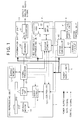
- FIG. 1 is a diagram illustrating an example of a schematic arrangement of an audio apparatus 100 in the present embodiment according to the present invention.
- the audio apparatus 100 in the present embodiment is provided with: a DVD (a Digital Video Disk or a Digital Versatile Disk) reproducing unit 1 for reproducing, as audio data, recording information recorded in a DVD serving as an information recording medium; an HDD recording/reproducing unit 2 for recording, reproducing the audio data transmitted from the DVD reproducing unit 1; an information output unit 3 in charge of an output processing of the audio data; a system control unit 4 in charge of an operation control of each of the above-described constituent units; and a power supply unit 5 for supplying power to the above-described constituent units.
- a DVD Digital Video Disk or a Digital Versatile Disk
- the DVD reproducing unit 1 includes: a spindle motor 10 for rotating the DVD carried to a predetermined clamping position at a constant linear velocity; a pickup 11 for optically reading the recording information recorded in the DVD; a signal processor 13 for demodulating the recording data read by the pickup 11, and further, for supplying the audio data contained in the recording data which has been time-division-multiplexed to the HDD recording/reproducing unit 2 and the information output unit 3 via a buffer memory 12; a servo circuit 14 for servo-controlling the spindle motor 10 and the pickup 11 in response to a tracking error signal or the like output from the signal processor 13; and a controller 15 for controlling the entire operation of the DVD reproducing unit 1.
- the controller 15 performs a proper synchronous reproduction in accordance with an instruction output from the system control unit 4.
- the DVD reproducing unit 1 has been well known and has no direct bearing on the present invention, and therefore, the detailed description thereof will be omitted below.
- a CD the acronym of a compact disk reproducing unit or the like may be used.
- the information output unit 3 is provided with a decoder 30 and a D/A converter 31.
- the decoder 30 is adapted to extend the audio data output from the DVD reproducing unit 1 or the HDD recording/reproducing unit 2. Thereafter, the D/A converter 31 converts the extended data into an analog audio signal, and then, outputs it to an amplifier and a speaker.
- the HDD recording/reproducing unit 2 includes a buffer memory 21, an HDD drive 22 and an HDD 23 serving as a recording device.
- the audio data output from the DVD reproducing unit 1 is temporarily stored in the buffer memory 21, and then, is recorded in the HDD 23 via the HDD drive 22.
- the HDD 23 includes a data recording region, in which the audio data is recorded in a predetermined unit (hereinafter referred to as "a block”); a first management data region (hereinafter referred to as “an FAT 1”) for storing management data for managing a recording status or the like in the above-described predetermined unit; and a second management data region (hereinafter referred to as “an FAT 2”) for storing the management data stored in the FAT 1 in the above-described predetermined unit.
- FIG. 2 is a chart conceptually illustrating the data recording region, the FAT 1 and the FAT 2 in the HDD 23. As illustrated, the audio data is recorded per cluster in the data recording region; in contrast, the management data is recorded in each of the FAT 1 and the FAT 2 in a manner corresponding to the data per cluster.
- one block signifies one cluster unit and one stream unit (i.e., a unit over a plurality of clusters).
- audio data "XXXX" in one cluster forms one block; and further, another audio data "YYYY " in one stream over three clusters forms one block.
- the plurality of sequent clusters form one stream in unit.
- the audio data is recorded or erased per block in the data recording region, as described later.
- the system control unit 4 includes a system controller 40 serving as a control device consisting of a CPU having an arithmetic function, a ROM, an operating RAM and the like; a nonvolatile memory 41 such as an EEPROM; and a operation/display 42 having operation buttons for inputting instructions from a user or a display for displaying predetermined information.
- a system controller 40 serving as a control device consisting of a CPU having an arithmetic function, a ROM, an operating RAM and the like; a nonvolatile memory 41 such as an EEPROM; and a operation/display 42 having operation buttons for inputting instructions from a user or a display for displaying predetermined information.
- the system controller 40 is adapted to control the entire apparatus based on a program stored in the ROM, and further, is equipped with a control processing function of performing, per block, a record processing of the audio data in the data recording region in the HDD 23 and an update processing of the management data to the FAT1 and the FAT2 in the HDD23 at that time. Additionally, the system controller 40 is equipped with another control processing function of performing, per block, an erasure processing of the audio data from the data recording region in the HDD 23 and the update processing of the management data to the FAT 1 and the FAT 2 in the HDD 23 at that time.
- FIG. 3 is a chart illustrating an example of the status data stored in the nonvolatile memory 41.
- the status data corresponds to an address of each of the clusters, and it includes the existence of sequence and a processing state flag.
- the sequence signifies the sequence of the clusters: "NO” designates that one block is completed with only that cluster without any sequence to a next cluster; to the contrary, "YES” designates that the sequence continues to a next cluster.
- the processing state flag indicates the status of the control processing of the system controller 40 in each of the clusters.
- A denotes the start of the recording or erasing of the audio data and updating of the FAT 1;
- B the start of the updating of the FAT 2;
- C the end of the recording, erasing and updating.
- the system controller 40 stores the status in each step in the control processing as the status data, thereby performing a proper restoration processing even if a trouble of power supply such as power shutdown occurs in the power supply unit 5 during the recording or erasing of the audio data.
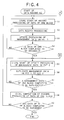
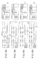
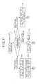
- FIG. 4 is a flowchart illustrating the control processing in the system controller 40 when the audio data is recorded; and FIGs. 5A to 5D are charts conceptually illustrating the audio data recording and the management data updating in the HDD 23 in the processing illustrated in FIG. 4 and the status data storing in the nonvolatile memory 41.
- the audio data "YYYY " in the above-described stream unit is exemplified in the following description.
- the system controller 40 gives an audio data reproducing instruction to the DVD reproducing unit 1 in accordance with a data recording instruction input by the user via the operation/display 42, and then, starts an audio data reproduction processing, and further, stores the processing state flag ("A") indicating the start of the record processing of the audio data (hereinafter, simply referred to as "the data") of one block in the nonvolatile memory 41 (step S1).
- the processing state flag ("A") corresponding to each of the clusters (addresses A0002, A0003 and B0001) in one block to be recorded is stored in the nonvolatile memory 41.
- the data is started to be recorded in the data recording region in the HDD 23 from the cluster (the address A0002) designated by reference numeral 50.
- the system controller 40 performs a record processing for recording the data in the data recording region in the HDD 23 (step S2), and then, it performs an update processing for updating the management data in the FAT 1 corresponding to the above-described data (step S3).
- the management data in the FAT 1 corresponding to the above-described data is updated from "0000" (indicating that no data is recorded) to "0001" (indicating that the data having the sequence is recorded).
- the sequence corresponding to the address A0002 becomes "YES".
- step S4 the system controller 40 judges as to whether or not the data of one block is completed to be recorded (step S4). Unless the data of one block has been completed to be recorded, the routine returns to step S2, in which next data is subjected to the record processing. For example, since the sequence of the cluster at the address A0002 is "YES", the data "YYYYYY” is recorded in a second cluster (i.e., the address A0003) of the block concerned, and then, the management data in the FAT 1 corresponding to the above-described data is updated from "0000" to "0002" (indicating that the data having the sequence is recorded) , as illustrated in FIG. 5B. Thus, the sequence corresponding to the address A0003 becomes "YES".
- step S5 For example, when the data in a last cluster designated by reference numeral 52 in FIG. 5B is completed to be recorded and the management data in the FAT 1 corresponding to the above-described data is updated, the sequence in the status data is recorded as "NO", and thus, the routine proceeds to step S5.
- the routine proceeds to step S5.
- it is judged as to whether or not the data of one block is completed to be recorded and the management data in the FAT 1 is completed to be updated.
- step S5 the system controller 40 stores a processing state flag ("B") indicating a start of an update processing for updating the management data in the FAT 2 in the nonvolatile memory 41. And then, the system controller 40 duplicates the management data in the FAT 1 to the FAT 2 (step S6). For example, when the processing state flag ("B") at the address A0003 is stored, as designated by reference numeral 53 in FIG. 5C, the management data in the FAT 1 corresponding to the address A0003 is duplicated to the FAT 2, as designated by reference numeral 54.
- step S7 the system controller 40 judges as to whether or not the management data of one block is completed to be duplicated to the FAT 2. If the management data is completed to be duplicated, the routine proceeds to step S8 . In contrast, unless the management data has been completed to be duplicated, the routine is repeated in steps S5 and S6 until all of the management data in one block are completed to be updated to the FAT 2.
- step S8 the system controller 40 stores, in the nonvolatile memory 41, a processing state flag ("C") indicating the completion of the record processing of the data of one block (i.e., the record processing in the data recording region and the update processing in the FAT 1 and the FAT 2).
- a processing state flag indicating the completion of the record processing of the data of one block (i.e., the record processing in the data recording region and the update processing in the FAT 1 and the FAT 2).
- the processing state flag (“C") corresponding to each of the clusters (the addresses A0002, A0003 and B0001) in one block to be recorded is stored in the nonvolatile memory 41, as designated by reference numeral 56.
- step S9 the system controller 40 judges as to whether or not the data of all of the blocks to be recorded are completed to be recorded. Unless the data of all of the blocks have been completed to be recorded, the routine returns to step S1, and then, the data of a next block is subjected to the same processing as described above (i.e., from steps S1 to S8). In contrast, if the data of all of the blocks have been completed to be recorded, the routine comes to an end.
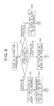
- FIG. 6 is a flowchart illustrating a restoration processing by the system controller 40 in the case where the trouble of the power supply such as the power shutdown occurs during the data recording; FIGs.
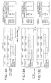
- FIGs. 7A to 7C are charts conceptually illustrating the data recording and the management data updating in the HDD 23 and the status data storing in the nonvolatile memory 41 in the case where the system controller 40 performs the restoration processing after the trouble of the power supply such as the power shutdown has occurred while the data is recorded in the data recording region;
- FIGs. 8A to 8C are charts conceptually illustrating the data recording and the management data updating in the HDD 23 and the status data storing in the nonvolatile memory 41 in the case where the system controller 40 performs the restoration processing after the trouble of the power supply such as the power shutdown has occurred while the management data is duplicated from the FAT 1 to the FAT 2.
- the system controller 40 starts the restoration processing.
- the system controller 40 refers to the status data stored in the nonvolatile memory 41, and then, judges the processing status of the final block being recorded (step S21). Specifically, in the case where all of the processing state flags corresponding to the blocks concerned are "A”, the routine proceeds to step S22. Otherwise, in the case where the processing state flags corresponding to the blocks concerned include "B”, the routine proceeds to step S24. Alternatively, in the case where all of the processing state flags corresponding to the blocks concerned are "C”, the routine proceeds to step S25.
- step S22 the system controller 40 sets the above-described final blocks as blocks to be recorded, and then, it controls to resume the recording from the above-described final blocks.
- the system controller 40 outputs, to the controller 15 in the DVD reproducing unit 1, a signal indicating the occurrence of the trouble of the power supply such as the power shutdown while the data is recorded in the data recording region.
- the controller 15 controls the servo circuit 14 in response to the signal output from the system controller 40, and then, returns the pickup 11 to a leading position of the recording information of one block which has been reproduced upon the occurrence of the trouble of the power supply such as the power shutdown, so as to allow it to stand by there.
- the system controller 40 duplicates, to the FAT 1, all of the management data of the final block in the FAT 2 (step S23), that is, returns the management data in the FAT 1 and the status data in the nonvolatile memory 41 to the state in which the final block is started to be recorded, as illustrated in FIG. 7B.
- the routine proceeds to step S1 illustrated in FIG. 4, as described above.
- the system controller 40 outputs a signal indicating the completion of the above-described restoration processing to the controller 15 in the DVD reproducing unit 1, so that the reproduction is resumed in the DVD reproducing unit 1, and further, the data is resumed to be recorded from the cluster corresponding to the first address A0002 in the final block, as illustrated in FIG. 7C.
- step S24 in which the system controller 40 sets the above-described final block as a block to be recorded, and then, controls to resume the updating of the management data in the FAT 2 from the above-described final block.
- the system controller 40 outputs, to the controller 15 in the DVD reproducing unit 1, a signal indicating that the trouble of the power supply such as the power shutdown occurs during the duplication of the management data from the FAT 1 to FAT 2.
- the controller 15 controls the servo circuit 14 in response to the signal output from the system controller 40, so as to allow the pickup 11 to stand by at a reproducing position at the timing when the trouble of the power supply such as the power shutdown occurs. That is to say, since the reproduction of the recording information of one block has been completed at this timing, the pickup 11 is allowed to stand by at a leading position of the recording information of one block to be reproduced next. Consequently, the status data stored in the nonvolatile memory 41 is returned to the state before the FAT 2 is updated.
- step S5 illustrated in FIG. 4.
- the processing is resumed from the duplication of the management data from the FAT 1 to the FAT 2 in the final block, as illustrated in FIGs. 8B and 8C.
- the system controller 40 outputs, to the controller 15 in the DVD reproducing unit 1, a signal indicating the completion of the duplication of the management data from the FAT 1 to the FAT 2, so that the reproduction of the recording information is resumed in the DVD reproducing unit 1, and further, the recording is resumed from the data of a block next to the final block.
- step S25 in which the system controller 40 sets a block next to the above-described final block as a block to be recorded, and then, controls to resume the record processing from the next block.
- the system controller 40 outputs, to the controller 15 in the DVD reproducing unit 1, a signal indicating that the trouble of the power supply such as the power shutdown occurs upon the completion of the recording processing of the data of one block.
- the controller 15 controls the servo circuit 14 in response to the signal output from the system controller 40, so as to resume the reproduction of the recording information from a reproducing position at the timing when the trouble of the power supply such as the power shutdown occurs, i.e., from a leading position of the recording information of one block to be reproduced next.
- the recording is resumed from the data of the block next to the final block.
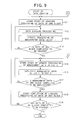
- FIG. 9 is a flowchart illustrating the control processing in the system controller 40 when the data is erased; and FIGs. 10A to 10D are charts conceptually illustrating the data erasing and the management data updating in the HDD 23 in the processing illustrated in FIG. 9 and the status data storing in the nonvolatile memory 41.
- the audio data "YYYY " in the above-described stream unit is exemplified in the following description, similarly to the above-described data recording case.
- the present embodiment will be explained on the case where the data is completely erased from the data recording region, it is not limited to such a case.
- the present invention can be applied to the configuration in which the data is considered to be erased even if the data remains in the data recording region.
- the system controller 40 starts a data erasing processing in accordance with a data erasing instruction input by the user via the operation/display 42, and further, stores the processing state flag ("A") indicating the start of the erasing processing of data of one block in the nonvolatile memory 41 (step S11).
- the processing state flag "A" corresponding to each of the clusters (the addresses A0002, A0003 and B0001) in one block to be erased is stored in the nonvolatile memory 41.
- the data is started to be erased from the data recording region in the HDD 23 from the cluster (the address A0002) designated by reference numeral 60.
- the system controller 40 performs an erasure processing for erasing data from the data recording region in the HDD 23 (step S12), and then, it performs an update processing for updating the management data in the FAT 1 corresponding to the above-described data (step S13).
- the management data in the FAT 1 corresponding to the above-described data is updated from "0001" (indicating the data having the sequence) to "0000" (indicating that no data is recorded).
- the sequence corresponding to the address A0002 becomes "YES".
- step S14 the system controller 40 judges as to whether or not the data of one block is completed to be erased (step S14). Unless the data of one block has been completed to be erased, the routine returns to step S12, in which next data is subjected to the erasure processing. For example, since the sequence of the cluster at the address A0002 is "YES", the data "YYYYYY” is erased in a second cluster (i.e., the address A0003) of the block concerned, and then, the management data in the FAT 1 corresponding to the above-described data is updated from "0002" (indicating the data having the sequence) to "0000", as illustrated in FIG. 10B. Thus, the sequence corresponding to the address A0003 becomes "YES".
- step S15 For example, when the data in a last cluster designated by reference numeral 62 in FIG. 10B is completed to be erased and the management data in the FAT 1 corresponding to the above-described data is updated, the sequence in the status data is recorded as "NO", and thus, the routine proceeds to step S15.
- the routine proceeds to step S15.
- it is judged as to whether or not the data of one block is completed to be erased and the management data in the FAT 1 is completed to be updated.
- step S15 the system controller 40 stores a processing state flag "B" indicating a start of an update processing for updating the management data in the FAT 2 in the nonvolatile memory 41. And then, the system controller 40 duplicates the management data in the FAT 1 to the FAT 2 (step S16). For example, when the processing state flag "B" at the address A0003 is stored, as designated by reference numeral 63 in FIG. 10C, the management data in the FAT 1 corresponding to the address A0003 is duplicated to the FAT 2, as designated by reference numeral 64.
- step S17 the system controller 40 judges as to whether or not the management data of one block is completed to be duplicated to the FAT 2. If the management data is completed to be duplicated, the routine proceeds to step S18. In contrast, unless the management data has been completed to be duplicated, the routine is repeated in steps S15 and S16 until all of the management data of one block are completed to be updated to the FAT 2.
- step S18 the system controller 40 stores, in the nonvolatile memory 41, a processing state flag "C" indicating the completion of the erasure processing of the data of one block (i.e., the erasure processing in the data recording region and the up date processing in the FAT 1 and the FAT 2).
- a processing state flag "C” indicating the completion of the erasure processing of the data of one block (i.e., the erasure processing in the data recording region and the up date processing in the FAT 1 and the FAT 2).
- the processing state flag "C" corresponding to each of the clusters (the addresses A0002, A0003 and B0001) in one block to be erased is stored in the nonvolatile memory 41, as designated by reference numeral 66.
- step S19 the system controller 40 judges as to whether or not the data of all of the blocks to be erased are completed to be erased. Unless the data of all of the blocks have been completed to be erased, the routine returns to step S11, and then, the data of a next block is subjected to the same processing as described above (i.e., from steps S11 to S18). In contrast, if the data of all of the blocks have been completed to be erased, the routine comes to an end.
- FIG. 11 is a flowchart illustrating a restoration processing by the system controller 40 in the case where the trouble of the power supply such as the power shutdown occurs during the data erasing; FIGs.
- FIGs. 12A to 12C are charts conceptually illustrating the data erasing and the management data updating in the HDD 23 and the status data storing in the nonvolatile memory 41 in the case where the system controller 40 performs the restoration processing after the trouble of the power supply such as the power shutdown has occurred while the data is erased from the data recording region; and FIGs. 13A to 13C are charts conceptually illustrating the data erasing and the management data updating in the HDD 23 and the status data storing in the nonvolatile memory 41 in the case where the system controller 40 performs the restoration processing after the trouble of the power supply such as the power shutdown has occurred while the management data is duplicated from the FAT 1 to the FAT 2.
- the system controller 40 starts the restoration processing.
- the system controller 40 refers to the status data stored in the nonvolatile memory 41, and then, judges the processing status of the final block being erased (step S31). Specifically, in the case where all of the processing state flags corresponding to the blocks concerned are "A”, the routine proceeds to step S32. Otherwise, in the case where the processing state flags corresponding to the blocks concerned include "B”, the routine proceeds to step S34. Alternatively, in the case where all of the processing state flags corresponding to the blocks concerned are "C”, the routine proceeds to step S35.
- step S32 the system controller 40 sets the above-described final blocks as blocks to be erased, and then, it controls to resume the erasing from the above-described final blocks.
- step S33 the system controller 40 duplicates, to the FAT 1, all of the management data of the final block in the FAT 2 (step S33), that is, returns the management data in the FAT 1 and the status data in the nonvolatile memory 41 to the state in which the final block is started to be erased, as illustrated in FIG. 12B.
- the routine proceeds to step S11 illustrated in FIG. 9, as described above. In this manner, the data is resumed to be erased from the cluster corresponding to the first address A0002 in the final block, as illustrated in FIG. 12C.
- step S34 in which the system controller 40 sets the above-described final block as a block to be erased, and then, controls to update the management data in the FAT 2 from the above-described final block.
- the status data stored in the nonvolatile memory 41 is returned to the state before the FAT 2 is updated.
- step S15 illustrated in FIG. 9.
- the processing is resumed from the duplication of the management data from the FAT 1 to the FAT 2 in the final block, as illustrated in FIGs. 13B and 13C.
- step S35 in which the system controller 40 sets a block next to the above-described final block as a block to be erased, and then, controls to resume the erasing from the next block. Subsequently, the routine by the system controller 40 proceeds to step S11 illustrated in FIG. 9. Thus, the erasing is resumed from the data of the block next to the final block.
- the management data in the FAT 1 is updated after the data (designated by reference numeral 50) of the first cluster is recorded, and then, the data in the next cluster is recorded.
- the management data in the FAT 1 may be updated after the data of all of the clusters in one block per stream are recorded (in the same manner as in FIG. 10).
- the status in each of the steps of the control processing is stored as the status data, so that the data recording or erasing status can be grasped after the restoration of the power, thereby properly performing the restoration processing per block at a high speed during the data record or erasure processing.
- one block is considered as the cluster or stream unit, it is not limited to this.
- the unit of such one block may be arbitrarily set, and therefore, a plurality of streams may be regarded as one block.
- the record and erasure processing of the data, and the duplication processing of the management data at the time of the restoration processing have been configured such that they have been performed per block, it may be performed, for example, per cluster in the case where one block is considered as one stream.
- the record processing may be resumed from the cluster concerned in the restoration processing in the case where the power shutdown occurs immediately after the data "YY" is recorded.
- nonvolatile memory is provided for storing the status data
- a volatile memory and a backup battery or the like in place of the nonvolatile memory may be combined with each other, so as to store the status data in the volatile memory.
- Such a configuration can produce the same effect as described above.
- no nonvolatile memory may be provided, and the status data may be stored in a predetermined storage region in the HDD, thereby producing the same effect as described above.
- the HDD 23 is used as the recording device, it is not limited to this, for example, a memory stick (card-type recording medium) or the like may be used.
- the data recording apparatus or the data erasing apparatus is configured such that the status data indicating the control processing status is stored in the predetermined unit by the control device, so that restoring measures can be taken in reference to the status data in the predetermined unit even if the trouble of the power supply such as the power shutdown occurs during, for example, the data record or erasure processing, thereby accurately restoring the data in a short time.
Landscapes
- Engineering & Computer Science (AREA)
- Signal Processing (AREA)
- General Engineering & Computer Science (AREA)
- Multimedia (AREA)
- Management Or Editing Of Information On Record Carriers (AREA)
- Signal Processing For Digital Recording And Reproducing (AREA)
- Power Sources (AREA)
- Techniques For Improving Reliability Of Storages (AREA)
- Memory System (AREA)
Priority Applications (1)
| Application Number | Priority Date | Filing Date | Title |
|---|---|---|---|
| EP05014535A EP1585135A3 (de) | 2001-06-04 | 2002-05-29 | Datenaufzeichnungs- und Datenlöschungsgerät |
Applications Claiming Priority (2)
| Application Number | Priority Date | Filing Date | Title |
|---|---|---|---|
| JP2001167942A JP2002358248A (ja) | 2001-06-04 | 2001-06-04 | データ記録装置およびデータ消去装置 |
| JP2001167942 | 2001-06-04 |
Related Child Applications (1)
| Application Number | Title | Priority Date | Filing Date |
|---|---|---|---|
| EP05014535A Division EP1585135A3 (de) | 2001-06-04 | 2002-05-29 | Datenaufzeichnungs- und Datenlöschungsgerät |
Publications (2)
| Publication Number | Publication Date |
|---|---|
| EP1265243A2 true EP1265243A2 (de) | 2002-12-11 |
| EP1265243A3 EP1265243A3 (de) | 2004-04-21 |
Family
ID=19010248
Family Applications (2)
| Application Number | Title | Priority Date | Filing Date |
|---|---|---|---|
| EP02011640A Withdrawn EP1265243A3 (de) | 2001-06-04 | 2002-05-29 | Datenaufzeichnungs- und Datenlöschungsgerät |
| EP05014535A Withdrawn EP1585135A3 (de) | 2001-06-04 | 2002-05-29 | Datenaufzeichnungs- und Datenlöschungsgerät |
Family Applications After (1)
| Application Number | Title | Priority Date | Filing Date |
|---|---|---|---|
| EP05014535A Withdrawn EP1585135A3 (de) | 2001-06-04 | 2002-05-29 | Datenaufzeichnungs- und Datenlöschungsgerät |
Country Status (4)
| Country | Link |
|---|---|
| US (1) | US6882493B2 (de) |
| EP (2) | EP1265243A3 (de) |
| JP (1) | JP2002358248A (de) |
| CN (1) | CN1242335C (de) |
Cited By (3)
| Publication number | Priority date | Publication date | Assignee | Title |
|---|---|---|---|---|
| EP1677306A1 (de) * | 2005-01-04 | 2006-07-05 | Deutsche Thomson-Brandt Gmbh | Verfahren zum Ändern des Arbeitens auf einem Speichermedium von einem aktuellen Dateisystem auf ein neues Dateisystem |
| EP1837772A1 (de) * | 2004-11-08 | 2007-09-26 | Ishida Co., Ltd. | Datenrecorder und güterverarbeitungsvorrichtung damit |
| EP2017840A1 (de) * | 2007-07-20 | 2009-01-21 | Teac Corporation | Optisches Plattenlaufwerk |
Families Citing this family (16)
| Publication number | Priority date | Publication date | Assignee | Title |
|---|---|---|---|---|
| JP2007149071A (ja) * | 2004-01-21 | 2007-06-14 | Orient Sokki Computer Kk | データクリーニング処理プログラム |
| JP4212486B2 (ja) * | 2004-01-22 | 2009-01-21 | 三洋電機株式会社 | 情報記録装置 |
| JP4500562B2 (ja) * | 2004-03-04 | 2010-07-14 | クラリオン株式会社 | 記憶装置、車載機器及び記憶装置の制御方法 |
| US7639926B2 (en) * | 2004-09-14 | 2009-12-29 | Marvell World Trade Ltd. | Unified control and memory for a combined DVD/HDD system |
| US7702221B2 (en) * | 2004-09-14 | 2010-04-20 | Marvell World Trade Ltd. | Unified control and memory for a combined DVD/HDD system |
| US7657160B2 (en) * | 2004-09-14 | 2010-02-02 | Marvell World Trade Ltd. | Unified control and memory for a combined DVD/HDD system |
| US7639927B2 (en) * | 2004-09-14 | 2009-12-29 | Marvell World Trade Ltd. | Unified control and memory for a combined DVD/HDD system |
| JP4679234B2 (ja) * | 2005-05-19 | 2011-04-27 | Hoya株式会社 | 動画記録装置 |
| US20070065105A1 (en) * | 2005-09-20 | 2007-03-22 | Mediatek Inc. | Data recovery method and system for a data recording |
| JP2007233638A (ja) * | 2006-02-28 | 2007-09-13 | Sony Corp | 情報処理装置、および情報処理方法、並びにコンピュータ・プログラム |
| JP4676378B2 (ja) * | 2006-05-18 | 2011-04-27 | 株式会社バッファロー | データ記憶装置およびデータ記憶方法 |
| KR101605907B1 (ko) * | 2007-01-04 | 2016-03-23 | 샌디스크 아이엘 엘티디 | 호스트와 데이터 저장 디바이스 사이의 파일 전송 실패의 복구 |
| US7747664B2 (en) * | 2007-01-16 | 2010-06-29 | Microsoft Corporation | Storage system format for transaction safe file system |
| JP4372168B2 (ja) * | 2007-02-19 | 2009-11-25 | 株式会社東芝 | 半導体メモリ情報蓄積装置とその蓄積データ処理方法 |
| TWI431464B (zh) * | 2009-04-29 | 2014-03-21 | Micro Star Int Co Ltd | Computer system with power control and power control method |
| CN101782875B (zh) * | 2010-01-29 | 2012-01-04 | 成都市华为赛门铁克科技有限公司 | 存储设备和数据存储方法 |
Citations (3)
| Publication number | Priority date | Publication date | Assignee | Title |
|---|---|---|---|---|
| EP0971358A2 (de) * | 1998-07-07 | 2000-01-12 | Matsushita Electric Industrial Co., Ltd. | Datenverarbeitungseinrichtung und Dateiverwaltungsverfahren dafür |
| US20010051954A1 (en) * | 2000-06-06 | 2001-12-13 | Kazuhiko Yamashita | Data updating apparatus that performs quick restoration processing |
| EP1172817A2 (de) * | 2000-07-14 | 2002-01-16 | Sony Corporation | Datenaufzeichnung/Wiedergabe |
Family Cites Families (5)
| Publication number | Priority date | Publication date | Assignee | Title |
|---|---|---|---|---|
| JPS6340949A (ja) * | 1986-08-06 | 1988-02-22 | Alps Electric Co Ltd | フアイル管理方法 |
| JPH09282103A (ja) * | 1995-12-22 | 1997-10-31 | Ricoh Co Ltd | 情報処理装置 |
| JP3588231B2 (ja) * | 1997-08-04 | 2004-11-10 | 東京エレクトロンデバイス株式会社 | データ処理システム及びブロック消去型記憶媒体 |
| JP4160139B2 (ja) * | 1997-12-12 | 2008-10-01 | オリンパス株式会社 | 情報記録再生装置 |
| JP4135049B2 (ja) * | 1999-03-25 | 2008-08-20 | ソニー株式会社 | 不揮発性メモリ |
-
2001
- 2001-06-04 JP JP2001167942A patent/JP2002358248A/ja not_active Abandoned
-
2002
- 2002-05-29 EP EP02011640A patent/EP1265243A3/de not_active Withdrawn
- 2002-05-29 EP EP05014535A patent/EP1585135A3/de not_active Withdrawn
- 2002-06-03 US US10/162,159 patent/US6882493B2/en not_active Expired - Fee Related
- 2002-06-04 CN CNB021222533A patent/CN1242335C/zh not_active Expired - Fee Related
Patent Citations (3)
| Publication number | Priority date | Publication date | Assignee | Title |
|---|---|---|---|---|
| EP0971358A2 (de) * | 1998-07-07 | 2000-01-12 | Matsushita Electric Industrial Co., Ltd. | Datenverarbeitungseinrichtung und Dateiverwaltungsverfahren dafür |
| US20010051954A1 (en) * | 2000-06-06 | 2001-12-13 | Kazuhiko Yamashita | Data updating apparatus that performs quick restoration processing |
| EP1172817A2 (de) * | 2000-07-14 | 2002-01-16 | Sony Corporation | Datenaufzeichnung/Wiedergabe |
Non-Patent Citations (1)
| Title |
|---|
| STEPHEN C. TWEEDIE: "Journaling the Linux ext2fs Filesystem" LINUXEXPO'98, [Online] 1998, pages 1-8, XP002270499 Retrieved from the Internet: <URL:http://www.osdever.net/docs/journal-d esign.pdf?the_id=38> [retrieved on 2004-02-16] * |
Cited By (5)
| Publication number | Priority date | Publication date | Assignee | Title |
|---|---|---|---|---|
| EP1837772A1 (de) * | 2004-11-08 | 2007-09-26 | Ishida Co., Ltd. | Datenrecorder und güterverarbeitungsvorrichtung damit |
| EP1837772A4 (de) * | 2004-11-08 | 2009-11-04 | Ishida Seisakusho | Datenrecorder und güterverarbeitungsvorrichtung damit |
| EP1677306A1 (de) * | 2005-01-04 | 2006-07-05 | Deutsche Thomson-Brandt Gmbh | Verfahren zum Ändern des Arbeitens auf einem Speichermedium von einem aktuellen Dateisystem auf ein neues Dateisystem |
| WO2006072535A1 (en) * | 2005-01-04 | 2006-07-13 | Thomson Licensing | Method for changing operation on a storage medium from a current file system to a new or updated file system |
| EP2017840A1 (de) * | 2007-07-20 | 2009-01-21 | Teac Corporation | Optisches Plattenlaufwerk |
Also Published As
| Publication number | Publication date |
|---|---|
| US6882493B2 (en) | 2005-04-19 |
| US20020181136A1 (en) | 2002-12-05 |
| CN1242335C (zh) | 2006-02-15 |
| EP1265243A3 (de) | 2004-04-21 |
| JP2002358248A (ja) | 2002-12-13 |
| EP1585135A3 (de) | 2006-01-04 |
| CN1389793A (zh) | 2003-01-08 |
| EP1585135A2 (de) | 2005-10-12 |
Similar Documents
| Publication | Publication Date | Title |
|---|---|---|
| US6882493B2 (en) | Data recording apparatus and data erasing apparatus capable of performing restoration when power supply malfunction occurs during recording or erasing | |
| JP3899030B2 (ja) | 記録再生装置の電力障害回復機構 | |
| JP3511916B2 (ja) | 記録再生装置 | |
| JPH11242850A (ja) | リアルタイムデータ記録方式 | |
| JP2610737B2 (ja) | 記録再生装置 | |
| JP3239854B2 (ja) | 記録再生装置 | |
| US7813248B2 (en) | Method and apparatus for protecting data when a recording process has failed | |
| JP2006228098A (ja) | データ処理方法、携帯型再生装置およびコンピュータ | |
| US20050259542A1 (en) | Reproduction device and method, recording medium, and program | |
| JP2014230003A (ja) | 編集装置及びその制御方法、プログラム、並びに記憶媒体 | |
| JPH06251562A (ja) | マルチボリウム連続記録装置 | |
| US8634692B2 (en) | Image recording/reproducing apparatus, control method thereof, program and storage medium | |
| JP2951149B2 (ja) | 記録再生装置 | |
| JP2009163791A (ja) | 光ディスク再生装置及び光ディスク再生装置のデータ管理方法 | |
| JPH07226062A (ja) | マルチメディアデータ再生装置 | |
| JP4058776B2 (ja) | 記録再生装置及び記録再生方法 | |
| KR100513351B1 (ko) | 디지털 녹화기에서의 파일 클로우즈 방법 | |
| JPH10124404A (ja) | 記録再生装置 | |
| JP2787839B2 (ja) | ディジタル録音装置 | |
| JP3368202B2 (ja) | 記録再生装置 | |
| JP2009037699A (ja) | コンテンツ記録再生信号処理装置およびコンテンツ記録再生装置 | |
| JP2000125240A (ja) | 記録再生装置におけるタイムコ−ド管理方式 | |
| JP2004104337A (ja) | 再生装置 | |
| JP2000207872A (ja) | 記録再生装置 | |
| JP2001283566A (ja) | 映像編集装置 |
Legal Events
| Date | Code | Title | Description |
|---|---|---|---|
| PUAI | Public reference made under article 153(3) epc to a published international application that has entered the european phase |
Free format text: ORIGINAL CODE: 0009012 |
|
| AK | Designated contracting states |
Kind code of ref document: A2 Designated state(s): AT BE CH CY DE DK ES FI FR GB GR IE IT LI LU MC NL PT SE TR |
|
| AX | Request for extension of the european patent |
Free format text: AL;LT;LV;MK;RO;SI |
|
| PUAL | Search report despatched |
Free format text: ORIGINAL CODE: 0009013 |
|
| AK | Designated contracting states |
Kind code of ref document: A3 Designated state(s): AT BE CH CY DE DK ES FI FR GB GR IE IT LI LU MC NL PT SE TR |
|
| AX | Request for extension of the european patent |
Extension state: AL LT LV MK RO SI |
|
| 17P | Request for examination filed |
Effective date: 20040420 |
|
| AKX | Designation fees paid |
Designated state(s): DE FR GB NL |
|
| 17Q | First examination report despatched |
Effective date: 20041222 |
|
| 17Q | First examination report despatched |
Effective date: 20041222 |
|
| STAA | Information on the status of an ep patent application or granted ep patent |
Free format text: STATUS: THE APPLICATION IS DEEMED TO BE WITHDRAWN |
|
| 18D | Application deemed to be withdrawn |
Effective date: 20081201 |