EP1264939A1 - Sicherheitsabschaltung für tiltbares Räumschild - Google Patents
Sicherheitsabschaltung für tiltbares Räumschild Download PDFInfo
- Publication number
- EP1264939A1 EP1264939A1 EP02009401A EP02009401A EP1264939A1 EP 1264939 A1 EP1264939 A1 EP 1264939A1 EP 02009401 A EP02009401 A EP 02009401A EP 02009401 A EP02009401 A EP 02009401A EP 1264939 A1 EP1264939 A1 EP 1264939A1
- Authority
- EP
- European Patent Office
- Prior art keywords
- groove
- ball
- bearing
- pin
- displacement sensor
- Prior art date
- Legal status (The legal status is an assumption and is not a legal conclusion. Google has not performed a legal analysis and makes no representation as to the accuracy of the status listed.)
- Granted
Links
- 238000006073 displacement reaction Methods 0.000 claims description 16
- 241001422033 Thestylus Species 0.000 claims description 12
- 238000005259 measurement Methods 0.000 claims 1
- 238000000034 method Methods 0.000 claims 1
- 230000005693 optoelectronics Effects 0.000 claims 1
- 230000004308 accommodation Effects 0.000 description 1
- 238000010276 construction Methods 0.000 description 1
- 238000005516 engineering process Methods 0.000 description 1
- 230000009993 protective function Effects 0.000 description 1
- 239000000523 sample Substances 0.000 description 1
- 239000002689 soil Substances 0.000 description 1
Images



Classifications
-
- F—MECHANICAL ENGINEERING; LIGHTING; HEATING; WEAPONS; BLASTING
- F41—WEAPONS
- F41H—ARMOUR; ARMOURED TURRETS; ARMOURED OR ARMED VEHICLES; MEANS OF ATTACK OR DEFENCE, e.g. CAMOUFLAGE, IN GENERAL
- F41H7/00—Armoured or armed vehicles
- F41H7/02—Land vehicles with enclosing armour, e.g. tanks
-
- E—FIXED CONSTRUCTIONS
- E02—HYDRAULIC ENGINEERING; FOUNDATIONS; SOIL SHIFTING
- E02F—DREDGING; SOIL-SHIFTING
- E02F3/00—Dredgers; Soil-shifting machines
- E02F3/04—Dredgers; Soil-shifting machines mechanically-driven
- E02F3/76—Graders, bulldozers, or the like with scraper plates or ploughshare-like elements; Levelling scarifying devices
- E02F3/7609—Scraper blade mounted forwardly of the tractor on a pair of pivoting arms which are linked to the sides of the tractor, e.g. bulldozers
- E02F3/7618—Scraper blade mounted forwardly of the tractor on a pair of pivoting arms which are linked to the sides of the tractor, e.g. bulldozers with the scraper blade adjustable relative to the pivoting arms about a horizontal axis
-
- E—FIXED CONSTRUCTIONS
- E02—HYDRAULIC ENGINEERING; FOUNDATIONS; SOIL SHIFTING
- E02F—DREDGING; SOIL-SHIFTING
- E02F3/00—Dredgers; Soil-shifting machines
- E02F3/04—Dredgers; Soil-shifting machines mechanically-driven
- E02F3/76—Graders, bulldozers, or the like with scraper plates or ploughshare-like elements; Levelling scarifying devices
- E02F3/80—Component parts
-
- E—FIXED CONSTRUCTIONS
- E02—HYDRAULIC ENGINEERING; FOUNDATIONS; SOIL SHIFTING
- E02F—DREDGING; SOIL-SHIFTING
- E02F3/00—Dredgers; Soil-shifting machines
- E02F3/04—Dredgers; Soil-shifting machines mechanically-driven
- E02F3/76—Graders, bulldozers, or the like with scraper plates or ploughshare-like elements; Levelling scarifying devices
- E02F3/80—Component parts
- E02F3/84—Drives or control devices therefor, e.g. hydraulic drive systems
- E02F3/844—Drives or control devices therefor, e.g. hydraulic drive systems for positioning the blade, e.g. hydraulically
- E02F3/845—Drives or control devices therefor, e.g. hydraulic drive systems for positioning the blade, e.g. hydraulically using mechanical sensors to determine the blade position, e.g. inclinometers, gyroscopes, pendulums
Definitions
- Armored vehicles often have a snow plow that also comes from the Earthworks technology is known, pre-built to allow soil and other objects can be put away.
- DE 31 38 666 describes a device for pivoting a Bucket proposed a swiveling of the bucket by vertical axis allows, whereby the clearing through the inclined Scraper in the direction of travel to the right or left of the lane is cleared when the carrier vehicle drives straight ahead.
- one tilting device In modern dozer systems, one tilting device is known, one Crossing of the sign in relation to the vehicle level or turning the Shield around the horizontal vehicle longitudinal axis and thus one enables more versatile use of the dozer blade.
- the maximum angle that the dozer blade faces the vehicle plane is pivoted is relatively small. For example, it is 7 degrees.
- the tilt drive for a dozer blade can be implemented in different ways become. If two hydraulic drives are arranged side by side, the is to raise or lower the dozer blade about an axis transverse to the direction of travel easy tilting, in which the drives or cylinders are not even be extended by one way, but in which the cylinders by one different way to be extended, which means appropriate Lever linkages and articulated bearings also the shield from the vehicle level and can be pivoted about the vehicle's longitudinal axis.
- a safety device is therefore required as a safety shutdown which switches off the tilt drive or only allows the sign to be inserted into the Starting position is pivoted back.
- the object of the invention is to provide a measuring device with a trigger device in the Storage of the dozer blade or to integrate at a suitable location as Safety device so that a maximum when tilting the dozer blade Tilt angle cannot be exceeded.
- a displacement sensor (13) with switch (16) is connected to the Spherical bearing (4, 7) attached that a certain angle between Spherical bearing ball and bearing housing to respond to the sensor and Triggering the switch leads.
- the switch leads to a corresponding one Interconnection and locking with the control of the shield drive that the shield drive is switched off.
- the angle between the bearing ball and Bearing housing occurs when two are arranged in parallel and side by side Shield drives that normally move the shield quite evenly by one horizontal axis lifting or lowering, extend unevenly so that the sign is tilted and thus inclined to the vehicle level. After the switch has responded, the sign only swings back permitted from the response position and up to the horizontal starting position.
- the advantage of the device is the protective function for the dozer blade system. Other advantages are the compact design with little space and the protected accommodation at the hinge of the shield. Furthermore, the Realization effort less than with a solution with displacement sensors in Hydraulic cylinder. Furthermore, the device is easy to replace Repair and the angular range for the release is variably adjustable.
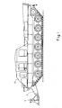
- the dozer blade system on a vehicle 17 consists of a Clearing blade 1 on the front of the vehicle, which is by means of spherical bearings 4 and two Räumschaufelarmen 2 is articulated on the vehicle.
- the clearing bucket arms 2 are rotatably mounted on an axle 5 on the vehicle and on an upper one End with the piston rods w1, w2 of two hydraulic cylinders 3 articulated connected.
- the hydraulic cylinders 3 are at the end of the housing 6 on the vehicle attached.
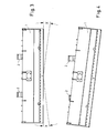
- the clearing blade 1 is shown seen from the front. outgoing from the starting position in Figure 3, the dozer blade by an angle x rotated right or left into a tilt position, such as in Figure 4. 5 shows the displacement and angle sensor 13.
- the cut open Spherical bearing housing 7 shows a bearing pin 8 with a spherical bearing 9.
- Die Ball 10 of the spherical plain bearing contains a circumferential groove 11 into which the Probe pin 12 of a displacement sensor 13 protrudes.
- the housing 14 of the Displacement sensor 13 sits in a bore in the bearing housing 7.
- the stylus 12 receives a bias by means of a spring 15 which the stylus 12 in its Push the zero position into the groove 11.
- the stylus 12 operated with his other End an electrical switch 16.
- a spherical bearing 4 which consists of a bearing pin 8 with a spherical bearing ball 10 as well as the bearing housing 7, the scraper is at two points the clearing bucket arms 2, which in turn have an axle 5 on the vehicle are stored, articulated.
- the bearing ball 10 has a groove all around 11.
- a displacement sensor 13 is with its housing 14 in a bore of the Bearing housing 7 used, the stylus 12 of the displacement sensor in the groove 11 protrudes.
- the stylus 12 is moved downwards by a spring 15 Grooved. At the upper end, the stylus actuates a switch 16.
- the two hydraulic cylinders 3, which are connected to the vehicle-side end of the Clearing bucket arms are connected on the one hand and on the other hand to the vehicle are stored, when the piston rod w1, w2 extend the Räumschaufelarme 2 about the axis 5 and thus move the to Spherical bearings 4 attached scraper 1 down or up. Further Drives, for example for rotating the shield around an axis on the shield, are omitted in Figure 2 for the sake of simplicity. At evenly Extending piston rods (w1 w2), the dozer blade is horizontally behind swiveled up or down. With, for example, unevenly extending The plow bar is also an horizontal one in Direction lying and imaginary axis rotated by an angle x in a Tiltgna.
- This angle x is also on the joint bearing 4 by means of a Travel sensor 13 tapped.
- the stylus 12 of the displacement sensor protrudes spring biased into the groove 11 of the ball 10 of the spherical bearing and gropes the groove.
- the stylus 12 moves out of the groove 11 and is raised, which triggers switch 16 at its other end.
- the Switch 16 switches off the hydraulic cylinders and thus prevents another Swiveling the dozer blade.
- the displacement / angle sensor 13 is advantageously at least at both bearing points 4 attached for security reasons.
Landscapes
- Engineering & Computer Science (AREA)
- General Engineering & Computer Science (AREA)
- Mechanical Engineering (AREA)
- Mining & Mineral Resources (AREA)
- Civil Engineering (AREA)
- Structural Engineering (AREA)
- Component Parts Of Construction Machinery (AREA)
- Crushing And Pulverization Processes (AREA)
- Soil Working Implements (AREA)
- Preliminary Treatment Of Fibers (AREA)
- Earth Drilling (AREA)
- Actuator (AREA)
Abstract
Description
- Figur 1:
- Genereller Aufbau eines Fahrzeuges mit Räumschildanlage
- Figur 2:
- Genereller Aufbau einer Räumschildanlage
- Figur 3:
- Beispiel: Normalstellung eines Räumschildes
- Figur 4:
- Beispiel: Tiltstellung eines Räumschildes
- Figur 5:
- Vorrichtung in Ruhestellung
- Figur 6:
- Vorrichtung in ausgelöster Stellung
Claims (10)
- Vorrichtung für ein Räumschild am Bug von Panzerfahrzeugen als Sicherheitseinrichtung zur Abschaltung der Schildantriebe, die das Schild verstellen und heben und senken, insbesondere bei Verwendung von zwei parallel angeordneten Hydraulikzylindern oder Antrieben, und mit messtechnischer Erfassung des Schwenk- oder Tiltwinkels des Schildes, wobei das Schild um eine waagerechte in Fahrtrichtung liegende Achse geschwenkt wird und die Abschaltung erfolgt, wenn ein maximaler Tiltwinkel erreicht und überschritten wird, dadurch gekennzeichnet, daß ein Wegsensor (13) eine Nut, die sich über eine Kugel eines Gelenklagers (4) erstreckt, abtastet und eine mögliche Verdrehung der Kugel feststellt, indem sich die Nut in ihrer Lage relativ zum Sensor verdreht, und der Sensor entsprechend der Nutabtastung einen Schalter betätigt, der den Schildantrieb abschaltet.
- Vorrichtung nach Anspruch 1 dadurch gekennzeichnet, daß die Kugel (10) des Gelenklagers (4) auf einem Lagerbolzen (8), der die Lagerung des Räumschildes (1) in einem Räumschildarm (2) bildet, befestigt ist und die Nut radial zu der Bolzenachse auf der Kugel umläuft.
- Vorrichtung nach Anspruch 1 und 2 dadurch gekennzeichnet, daß der Wegsensor (13) im Lagergehäuse des Gelenklagers (4) senkrecht zur Bolzen- bzw. Kugelachse von Bolzen (8) bzw. Kugel (10) in einer Gehäusebohrung befestigt ist, so daß die Abtastung der Nut (11) zum Beispiel mittels Abtaststift (12) senkrecht unterhalb vom Wegaufnehmer erfolgt.
- Vorrichtung nach einem der oben genannten Ansprüche dadurch gekennzeichnet, daß der Abtaststift (12) mittels einer Feder (15) gegen die Nut (11) nach unten vorgespannt ist.
- Vorrichtung nach einem der oben genannten Ansprüche dadurch gekennzeichnet, daß der Abtaststift (12) mit einem Ende einen zum Beispiel elektrischen Schalter (16) betätigt, der zum Beispiel die Steuerspannung für die Steuerung der Hydraulikzylinder ein- oder ausschaltet.
- Vorrichtung nach einem der oben genannten Ansprüche dadurch gekennzeichnet, daß die Nut (11) durch ihre geometrische Formgebung derart passend zu dem Ende des Abtaststifts (12) ausgeformt ist, daß bei Schrägstellung von Bolzen (8) und damit Verdrehung von Lagerkugel (10) um einen gewissen Winkelwert der Stift (12) aus der Nut (11) ausgehoben und um eine Wegstrecke, die der Nuttiefe entspricht, als Schaltweg nach oben in Richtung des Schalters (16) verschoben wird.
- Vorrichtung nach einem der oben genannten Ansprüche dadurch gekennzeichnet, daß der Taststift (12) des Wegsensors (13) oder der gesamte Wegsensor leicht auswechselbar ausgeführt ist und mittels Taststiftdicke und -formgebung ein entsprechend verschiedener Schaltwinkel einrichtbar ist.
- Vorrichtung nach einem der oben genannten Ansprüche dadurch gekennzeichnet, daß andere Verfahren der Sensierung der Lageveränderung der Nut in der Gelenkkugel für den Wegsensor verwendet werden zum Beispiel eine optoelektronische Sensierung.
- Vorrichtung nach einem der oben genannten Ansprüche dadurch gekennzeichnet, daß die Vorrichtung an Gelenklagern (4) von einem Räumschild (1) angewendet wird, welches mittels der Gelenklager (4) an zwei parallelen Räumschildarmen (2) angelenkt ist und die Räumschildarme mit Lagern entsprechend einer Achse (5) an einem Fahrzeug gelagert sind und die Arme (2) an ihrem einen Ende mittels zwei parallelen Hydraulikzylindern (3), die ihrerseits mit einem Ende (6) beweglich am Fahrzeug befestigt sind, angetrieben werden und das Räumschild angehoben oder abgesenkt wird.
- Vorrichtung nach einem der oben genannten Ansprüche dadurch gekennzeichnet, daß die Verwendung an einer Räumschildanordnung erfolgt, bei der zwei Hydrozylinder (3) jeweils eine verschiedene Wegstrecke w1 und w2 ausgefahren werden, wodurch das Räumschild (1) um eine Achse entsprechend der Fahrzeuglängsachse geschwenkt wird.
Applications Claiming Priority (2)
| Application Number | Priority Date | Filing Date | Title |
|---|---|---|---|
| DE10127588 | 2001-06-06 | ||
| DE10127588A DE10127588C2 (de) | 2001-06-06 | 2001-06-06 | Sicherheitsabschaltung für tiltbares Räumschild |
Publications (2)
| Publication Number | Publication Date |
|---|---|
| EP1264939A1 true EP1264939A1 (de) | 2002-12-11 |
| EP1264939B1 EP1264939B1 (de) | 2010-01-06 |
Family
ID=7687468
Family Applications (1)
| Application Number | Title | Priority Date | Filing Date |
|---|---|---|---|
| EP02009401A Expired - Lifetime EP1264939B1 (de) | 2001-06-06 | 2002-04-25 | Sicherheitsabschaltung für tiltbares Räumschild |
Country Status (5)
| Country | Link |
|---|---|
| EP (1) | EP1264939B1 (de) |
| AT (1) | ATE454502T1 (de) |
| DE (2) | DE10127588C2 (de) |
| ES (1) | ES2337447T3 (de) |
| NO (1) | NO20022226L (de) |
Cited By (1)
| Publication number | Priority date | Publication date | Assignee | Title |
|---|---|---|---|---|
| WO2011060472A1 (de) * | 2009-11-19 | 2011-05-26 | Bernhard Petermeier | Omnidirektionale beförderungsplattform |
Families Citing this family (1)
| Publication number | Priority date | Publication date | Assignee | Title |
|---|---|---|---|---|
| DE102009019865A1 (de) * | 2009-05-06 | 2010-11-18 | Rheinmetall Landsysteme Gmbh | Rad- oder Kettenfahrzeug mit einer an dem Fahrzeug angeordneten Räum- und/oder Stützanlage |
Citations (4)
| Publication number | Priority date | Publication date | Assignee | Title |
|---|---|---|---|---|
| DE2902450A1 (de) * | 1979-01-23 | 1980-07-31 | Gewerk Eisenhuette Westfalia | Anlenkung eines hubgeraetes, insbesondere einer ladeschaufel, eines planierschildes oder einer balkenabstuetzung o.dgl., an einer fahrbaren arbeitsmaschine |
| JPS5869939A (ja) * | 1981-10-22 | 1983-04-26 | Komatsu Ltd | 建設機械におけるブレ−ドの制御装置 |
| DE3141462A1 (de) * | 1981-10-19 | 1983-05-05 | Bundesrepublik Deutschland, vertreten durch den Bundesminister der Verteidigung, dieser vertreten durch den Präsidenten des Bundesamtes für Wehrtechnik und Beschaffung, 5400 Koblenz | Schaltungsanordnung zur einstellung einer raeumschaufel an fahrzeugen |
| US5069296A (en) * | 1990-06-05 | 1991-12-03 | Case Corporation | Pitch/tilt dozer |
Family Cites Families (6)
| Publication number | Priority date | Publication date | Assignee | Title |
|---|---|---|---|---|
| DE1956188C3 (de) * | 1969-11-07 | 1975-11-06 | Centralnyj Naucno-Issledovatelskij Institut Transportnogo Stroitelstva, Moskau | Schaufelartiger Planierschild |
| DE2758461C3 (de) * | 1977-12-28 | 1981-07-30 | Franz Xaver Meiller Fahrzeug- und Maschinenfabrik - GmbH & Co KG, 8000 München | Fahrzeug mit einem an ihm anschließbaren Arbeitsgerät |
| DE3039364A1 (de) * | 1980-10-18 | 1982-05-19 | Dr.Ing.H.C. F. Porsche Ag, 7000 Stuttgart | Raeum- und abstuetzschild fuer bergefahrzeuge, insbesondere fuer bergepanzer |
| DE3101899A1 (de) * | 1981-01-22 | 1982-09-02 | Krupp Mak Maschinenbau Gmbh, 2300 Kiel | Raeum- und stuetzschild fuer panzerfahrzeuge |
| DE3138666A1 (de) * | 1981-09-29 | 1983-04-14 | Krupp Mak Maschinenbau Gmbh, 2300 Kiel | "vorrichtung zum verschwenken einer raeumschaufel" |
| DE3404772A1 (de) * | 1984-02-10 | 1985-08-14 | Dr.Ing.H.C. F. Porsche Ag, 7000 Stuttgart | Raeum- und stuetzschild fuer panzerfahrzeuge |
-
2001
- 2001-06-06 DE DE10127588A patent/DE10127588C2/de not_active Expired - Fee Related
-
2002
- 2002-04-25 EP EP02009401A patent/EP1264939B1/de not_active Expired - Lifetime
- 2002-04-25 ES ES02009401T patent/ES2337447T3/es not_active Expired - Lifetime
- 2002-04-25 DE DE50214142T patent/DE50214142D1/de not_active Expired - Lifetime
- 2002-04-25 AT AT02009401T patent/ATE454502T1/de not_active IP Right Cessation
- 2002-05-10 NO NO20022226A patent/NO20022226L/no not_active Application Discontinuation
Patent Citations (4)
| Publication number | Priority date | Publication date | Assignee | Title |
|---|---|---|---|---|
| DE2902450A1 (de) * | 1979-01-23 | 1980-07-31 | Gewerk Eisenhuette Westfalia | Anlenkung eines hubgeraetes, insbesondere einer ladeschaufel, eines planierschildes oder einer balkenabstuetzung o.dgl., an einer fahrbaren arbeitsmaschine |
| DE3141462A1 (de) * | 1981-10-19 | 1983-05-05 | Bundesrepublik Deutschland, vertreten durch den Bundesminister der Verteidigung, dieser vertreten durch den Präsidenten des Bundesamtes für Wehrtechnik und Beschaffung, 5400 Koblenz | Schaltungsanordnung zur einstellung einer raeumschaufel an fahrzeugen |
| JPS5869939A (ja) * | 1981-10-22 | 1983-04-26 | Komatsu Ltd | 建設機械におけるブレ−ドの制御装置 |
| US5069296A (en) * | 1990-06-05 | 1991-12-03 | Case Corporation | Pitch/tilt dozer |
Non-Patent Citations (1)
| Title |
|---|
| PATENT ABSTRACTS OF JAPAN vol. 007, no. 163 (M - 229) 16 July 1983 (1983-07-16) * |
Cited By (1)
| Publication number | Priority date | Publication date | Assignee | Title |
|---|---|---|---|---|
| WO2011060472A1 (de) * | 2009-11-19 | 2011-05-26 | Bernhard Petermeier | Omnidirektionale beförderungsplattform |
Also Published As
| Publication number | Publication date |
|---|---|
| DE50214142D1 (de) | 2010-02-25 |
| DE10127588C2 (de) | 2003-07-03 |
| ATE454502T1 (de) | 2010-01-15 |
| ES2337447T3 (es) | 2010-04-26 |
| DE10127588A1 (de) | 2003-01-09 |
| NO20022226D0 (no) | 2002-05-10 |
| EP1264939B1 (de) | 2010-01-06 |
| NO20022226L (no) | 2002-12-09 |
Similar Documents
| Publication | Publication Date | Title |
|---|---|---|
| EP2275604B1 (de) | Baugerät für den Tiefbau | |
| EP2695994B1 (de) | Selbstfahrende Baumaschine | |
| EP3103928A1 (de) | Baufahrzeug mit verkippbarem fahrgestell | |
| DE20209866U1 (de) | Einstellvorrichtung für ein Trittbrett einer Tretmühle | |
| DE202014000508U1 (de) | Bohrgerät | |
| DE102010041466A1 (de) | Vorrichtung zum Positionieren eines Werkstücks | |
| DE10127588C2 (de) | Sicherheitsabschaltung für tiltbares Räumschild | |
| DE2835270A1 (de) | Strassenhobel mit einer aufhaengung fuer seine schneidvorrichtung | |
| DE102009033917A1 (de) | Fahrzeug mit ausschwenkbarem Mastarmaufbau | |
| EP0493714B1 (de) | Steuerungsmechanismus für drei Funktionen mit einem ersten und einem zweiten Steuerhebel | |
| EP1191303A2 (de) | Gepanzertes Fahrzeug, insbesondere Kampffahrzeug | |
| EP0565833A1 (de) | Vorrichtung zum lotrechten Ausrichten der Hochachse eines mit einem Untergestell dreh- und neigungsverstellbar verbundenen Aufbaus | |
| DE69725701T2 (de) | Strassendeckenfräsgerät | |
| DE102009006564C5 (de) | Kraftfahrzeug mit einer an einem Basisfahrzeug bugseitig angeordneten Stützanlage | |
| DE3931547C2 (de) | Löffelbaggerfahrzeug | |
| DE202013000211U1 (de) | Vorrichtung zur stellbeweglichen Aufnahme von Solarmodulen | |
| DE3101899C2 (de) | ||
| EP0354556B1 (de) | Stein-Verlegemaschine | |
| DE3909668C2 (de) | ||
| EP1734190A1 (de) | Vorrichtung zum Bearbeiten von Strassenbauflächen | |
| EP1710198B1 (de) | Transportable Arbeitsmaschine mit einem auf einem Drehtisch montierten Auslegerarm | |
| EP3054367A2 (de) | Fahrzeug, insbesondere kettenfahrzeug zur schneepistengestaltung und -pflege | |
| EP0557763A2 (de) | Strassenfräse | |
| DE7827488U1 (de) | Fuehrungs- und positioniermechanismus fuer das arbeitswerkzeug von stichlochbohr- oder stichlochstopfmaschinen an schachtoefen | |
| DE602005002289T2 (de) | Mechanismus für einen Fördertragarm und Tragarmvorrichtung mit solchem Mechanismus |
Legal Events
| Date | Code | Title | Description |
|---|---|---|---|
| PUAI | Public reference made under article 153(3) epc to a published international application that has entered the european phase |
Free format text: ORIGINAL CODE: 0009012 |
|
| 17P | Request for examination filed |
Effective date: 20020920 |
|
| AK | Designated contracting states |
Kind code of ref document: A1 Designated state(s): AT BE CH CY DE DK ES FI FR GB GR IE IT LI LU MC NL PT SE TR |
|
| AX | Request for extension of the european patent |
Free format text: AL;LT;LV;MK;RO;SI |
|
| AKX | Designation fees paid |
Designated state(s): AT BE CH CY DE DK ES FI FR GB GR IE IT LI LU MC NL PT SE TR |
|
| RAP1 | Party data changed (applicant data changed or rights of an application transferred) |
Owner name: RHEINMETALL LANDSYSTEME GMBH |
|
| 17Q | First examination report despatched |
Effective date: 20070731 |
|
| GRAP | Despatch of communication of intention to grant a patent |
Free format text: ORIGINAL CODE: EPIDOSNIGR1 |
|
| GRAS | Grant fee paid |
Free format text: ORIGINAL CODE: EPIDOSNIGR3 |
|
| GRAA | (expected) grant |
Free format text: ORIGINAL CODE: 0009210 |
|
| AK | Designated contracting states |
Kind code of ref document: B1 Designated state(s): AT BE CH CY DE DK ES FI FR GB GR IE IT LI LU MC NL PT SE TR |
|
| REG | Reference to a national code |
Ref country code: GB Ref legal event code: FG4D Free format text: NOT ENGLISH |
|
| REG | Reference to a national code |
Ref country code: CH Ref legal event code: EP |
|
| REG | Reference to a national code |
Ref country code: IE Ref legal event code: FG4D |
|
| REF | Corresponds to: |
Ref document number: 50214142 Country of ref document: DE Date of ref document: 20100225 Kind code of ref document: P |
|
| REG | Reference to a national code |
Ref country code: ES Ref legal event code: FG2A Ref document number: 2337447 Country of ref document: ES Kind code of ref document: T3 |
|
| REG | Reference to a national code |
Ref country code: NL Ref legal event code: VDEP Effective date: 20100106 |
|
| REG | Reference to a national code |
Ref country code: CH Ref legal event code: NV Representative=s name: E. BLUM & CO. AG PATENT- UND MARKENANWAELTE VSP |
|
| PGFP | Annual fee paid to national office [announced via postgrant information from national office to epo] |
Ref country code: TR Payment date: 20100323 Year of fee payment: 9 |
|
| PG25 | Lapsed in a contracting state [announced via postgrant information from national office to epo] |
Ref country code: PT Free format text: LAPSE BECAUSE OF FAILURE TO SUBMIT A TRANSLATION OF THE DESCRIPTION OR TO PAY THE FEE WITHIN THE PRESCRIBED TIME-LIMIT Effective date: 20100506 Ref country code: NL Free format text: LAPSE BECAUSE OF FAILURE TO SUBMIT A TRANSLATION OF THE DESCRIPTION OR TO PAY THE FEE WITHIN THE PRESCRIBED TIME-LIMIT Effective date: 20100106 |
|
| PGFP | Annual fee paid to national office [announced via postgrant information from national office to epo] |
Ref country code: ES Payment date: 20100427 Year of fee payment: 9 Ref country code: FR Payment date: 20100506 Year of fee payment: 9 |
|
| REG | Reference to a national code |
Ref country code: IE Ref legal event code: FD4D |
|
| PG25 | Lapsed in a contracting state [announced via postgrant information from national office to epo] |
Ref country code: FI Free format text: LAPSE BECAUSE OF FAILURE TO SUBMIT A TRANSLATION OF THE DESCRIPTION OR TO PAY THE FEE WITHIN THE PRESCRIBED TIME-LIMIT Effective date: 20100106 |
|
| PG25 | Lapsed in a contracting state [announced via postgrant information from national office to epo] |
Ref country code: GR Free format text: LAPSE BECAUSE OF FAILURE TO SUBMIT A TRANSLATION OF THE DESCRIPTION OR TO PAY THE FEE WITHIN THE PRESCRIBED TIME-LIMIT Effective date: 20100407 Ref country code: IE Free format text: LAPSE BECAUSE OF FAILURE TO SUBMIT A TRANSLATION OF THE DESCRIPTION OR TO PAY THE FEE WITHIN THE PRESCRIBED TIME-LIMIT Effective date: 20100106 Ref country code: SE Free format text: LAPSE BECAUSE OF FAILURE TO SUBMIT A TRANSLATION OF THE DESCRIPTION OR TO PAY THE FEE WITHIN THE PRESCRIBED TIME-LIMIT Effective date: 20100106 Ref country code: CY Free format text: LAPSE BECAUSE OF FAILURE TO SUBMIT A TRANSLATION OF THE DESCRIPTION OR TO PAY THE FEE WITHIN THE PRESCRIBED TIME-LIMIT Effective date: 20100106 |
|
| PGFP | Annual fee paid to national office [announced via postgrant information from national office to epo] |
Ref country code: CH Payment date: 20100423 Year of fee payment: 9 |
|
| BERE | Be: lapsed |
Owner name: RHEINMETALL LANDSYSTEME G.M.B.H. Effective date: 20100430 |
|
| PLBE | No opposition filed within time limit |
Free format text: ORIGINAL CODE: 0009261 |
|
| STAA | Information on the status of an ep patent application or granted ep patent |
Free format text: STATUS: NO OPPOSITION FILED WITHIN TIME LIMIT |
|
| PG25 | Lapsed in a contracting state [announced via postgrant information from national office to epo] |
Ref country code: MC Free format text: LAPSE BECAUSE OF NON-PAYMENT OF DUE FEES Effective date: 20100430 |
|
| PGFP | Annual fee paid to national office [announced via postgrant information from national office to epo] |
Ref country code: GB Payment date: 20100420 Year of fee payment: 9 |
|
| 26N | No opposition filed |
Effective date: 20101007 |
|
| PG25 | Lapsed in a contracting state [announced via postgrant information from national office to epo] |
Ref country code: DK Free format text: LAPSE BECAUSE OF FAILURE TO SUBMIT A TRANSLATION OF THE DESCRIPTION OR TO PAY THE FEE WITHIN THE PRESCRIBED TIME-LIMIT Effective date: 20100106 |
|
| PG25 | Lapsed in a contracting state [announced via postgrant information from national office to epo] |
Ref country code: IT Free format text: LAPSE BECAUSE OF FAILURE TO SUBMIT A TRANSLATION OF THE DESCRIPTION OR TO PAY THE FEE WITHIN THE PRESCRIBED TIME-LIMIT Effective date: 20100106 Ref country code: BE Free format text: LAPSE BECAUSE OF NON-PAYMENT OF DUE FEES Effective date: 20100430 |
|
| PG25 | Lapsed in a contracting state [announced via postgrant information from national office to epo] |
Ref country code: AT Free format text: LAPSE BECAUSE OF NON-PAYMENT OF DUE FEES Effective date: 20100425 |
|
| REG | Reference to a national code |
Ref country code: CH Ref legal event code: PL |
|
| GBPC | Gb: european patent ceased through non-payment of renewal fee |
Effective date: 20110425 |
|
| REG | Reference to a national code |
Ref country code: FR Ref legal event code: ST Effective date: 20111230 |
|
| PG25 | Lapsed in a contracting state [announced via postgrant information from national office to epo] |
Ref country code: CH Free format text: LAPSE BECAUSE OF NON-PAYMENT OF DUE FEES Effective date: 20110430 Ref country code: FR Free format text: LAPSE BECAUSE OF NON-PAYMENT OF DUE FEES Effective date: 20110502 Ref country code: LI Free format text: LAPSE BECAUSE OF NON-PAYMENT OF DUE FEES Effective date: 20110430 |
|
| PG25 | Lapsed in a contracting state [announced via postgrant information from national office to epo] |
Ref country code: GB Free format text: LAPSE BECAUSE OF NON-PAYMENT OF DUE FEES Effective date: 20110425 |
|
| PG25 | Lapsed in a contracting state [announced via postgrant information from national office to epo] |
Ref country code: LU Free format text: LAPSE BECAUSE OF NON-PAYMENT OF DUE FEES Effective date: 20100425 |
|
| REG | Reference to a national code |
Ref country code: ES Ref legal event code: FD2A Effective date: 20131029 |
|
| PG25 | Lapsed in a contracting state [announced via postgrant information from national office to epo] |
Ref country code: TR Free format text: LAPSE BECAUSE OF NON-PAYMENT OF DUE FEES Effective date: 20110425 Ref country code: ES Free format text: LAPSE BECAUSE OF NON-PAYMENT OF DUE FEES Effective date: 20110426 |
|
| PGFP | Annual fee paid to national office [announced via postgrant information from national office to epo] |
Ref country code: DE Payment date: 20210420 Year of fee payment: 20 |
|
| REG | Reference to a national code |
Ref country code: DE Ref legal event code: R071 Ref document number: 50214142 Country of ref document: DE |