EP1255151B1 - Bildeingabevorrichtung - Google Patents
Bildeingabevorrichtung Download PDFInfo
- Publication number
- EP1255151B1 EP1255151B1 EP02077920A EP02077920A EP1255151B1 EP 1255151 B1 EP1255151 B1 EP 1255151B1 EP 02077920 A EP02077920 A EP 02077920A EP 02077920 A EP02077920 A EP 02077920A EP 1255151 B1 EP1255151 B1 EP 1255151B1
- Authority
- EP
- European Patent Office
- Prior art keywords
- input device
- image input
- mirror body
- housing
- linear sensor
- Prior art date
- Legal status (The legal status is an assumption and is not a legal conclusion. Google has not performed a legal analysis and makes no representation as to the accuracy of the status listed.)
- Expired - Lifetime
Links
Images


Classifications
-
- H—ELECTRICITY
- H04—ELECTRIC COMMUNICATION TECHNIQUE
- H04N—PICTORIAL COMMUNICATION, e.g. TELEVISION
- H04N1/00—Scanning, transmission or reproduction of documents or the like, e.g. facsimile transmission; Details thereof
- H04N1/00795—Reading arrangements
- H04N1/00827—Arrangements for reading an image from an unusual original, e.g. 3-dimensional objects
-
- G—PHYSICS
- G02—OPTICS
- G02B—OPTICAL ELEMENTS, SYSTEMS OR APPARATUS
- G02B26/00—Optical devices or arrangements for the control of light using movable or deformable optical elements
- G02B26/08—Optical devices or arrangements for the control of light using movable or deformable optical elements for controlling the direction of light
- G02B26/10—Scanning systems
- G02B26/12—Scanning systems using multifaceted mirrors
-
- H—ELECTRICITY
- H04—ELECTRIC COMMUNICATION TECHNIQUE
- H04N—PICTORIAL COMMUNICATION, e.g. TELEVISION
- H04N1/00—Scanning, transmission or reproduction of documents or the like, e.g. facsimile transmission; Details thereof
- H04N1/00795—Reading arrangements
-
- H—ELECTRICITY
- H04—ELECTRIC COMMUNICATION TECHNIQUE
- H04N—PICTORIAL COMMUNICATION, e.g. TELEVISION
- H04N1/00—Scanning, transmission or reproduction of documents or the like, e.g. facsimile transmission; Details thereof
- H04N1/04—Scanning arrangements, i.e. arrangements for the displacement of active reading or reproducing elements relative to the original or reproducing medium, or vice versa
- H04N1/113—Scanning arrangements, i.e. arrangements for the displacement of active reading or reproducing elements relative to the original or reproducing medium, or vice versa using oscillating or rotating mirrors
-
- H—ELECTRICITY
- H04—ELECTRIC COMMUNICATION TECHNIQUE
- H04N—PICTORIAL COMMUNICATION, e.g. TELEVISION
- H04N23/00—Cameras or camera modules comprising electronic image sensors; Control thereof
- H04N23/56—Cameras or camera modules comprising electronic image sensors; Control thereof provided with illuminating means
-
- H—ELECTRICITY
- H04—ELECTRIC COMMUNICATION TECHNIQUE
- H04N—PICTORIAL COMMUNICATION, e.g. TELEVISION
- H04N3/00—Scanning details of television systems; Combination thereof with generation of supply voltages
- H04N3/02—Scanning details of television systems; Combination thereof with generation of supply voltages by optical-mechanical means only
- H04N3/08—Scanning details of television systems; Combination thereof with generation of supply voltages by optical-mechanical means only having a moving reflector
-
- H—ELECTRICITY
- H04—ELECTRIC COMMUNICATION TECHNIQUE
- H04N—PICTORIAL COMMUNICATION, e.g. TELEVISION
- H04N1/00—Scanning, transmission or reproduction of documents or the like, e.g. facsimile transmission; Details thereof
- H04N1/04—Scanning arrangements, i.e. arrangements for the displacement of active reading or reproducing elements relative to the original or reproducing medium, or vice versa
- H04N1/10—Scanning arrangements, i.e. arrangements for the displacement of active reading or reproducing elements relative to the original or reproducing medium, or vice versa using flat picture-bearing surfaces
-
- H—ELECTRICITY
- H04—ELECTRIC COMMUNICATION TECHNIQUE
- H04N—PICTORIAL COMMUNICATION, e.g. TELEVISION
- H04N1/00—Scanning, transmission or reproduction of documents or the like, e.g. facsimile transmission; Details thereof
- H04N1/04—Scanning arrangements, i.e. arrangements for the displacement of active reading or reproducing elements relative to the original or reproducing medium, or vice versa
- H04N1/19—Scanning arrangements, i.e. arrangements for the displacement of active reading or reproducing elements relative to the original or reproducing medium, or vice versa using multi-element arrays
- H04N1/191—Scanning arrangements, i.e. arrangements for the displacement of active reading or reproducing elements relative to the original or reproducing medium, or vice versa using multi-element arrays the array comprising a one-dimensional [1D] array
- H04N1/192—Simultaneously or substantially simultaneously scanning picture elements on one main scanning line
- H04N1/193—Simultaneously or substantially simultaneously scanning picture elements on one main scanning line using electrically scanned linear arrays, e.g. linear CCD arrays
-
- H—ELECTRICITY
- H04—ELECTRIC COMMUNICATION TECHNIQUE
- H04N—PICTORIAL COMMUNICATION, e.g. TELEVISION
- H04N2201/00—Indexing scheme relating to scanning, transmission or reproduction of documents or the like, and to details thereof
- H04N2201/04—Scanning arrangements
- H04N2201/0402—Arrangements not specific to a particular one of the scanning methods covered by groups H04N1/04 - H04N1/207
- H04N2201/0436—Scanning a picture-bearing surface lying face up on a support
-
- H—ELECTRICITY
- H04—ELECTRIC COMMUNICATION TECHNIQUE
- H04N—PICTORIAL COMMUNICATION, e.g. TELEVISION
- H04N2201/00—Indexing scheme relating to scanning, transmission or reproduction of documents or the like, and to details thereof
- H04N2201/04—Scanning arrangements
- H04N2201/0402—Arrangements not specific to a particular one of the scanning methods covered by groups H04N1/04 - H04N1/207
- H04N2201/045—Mounting the scanning elements in a collapsible or foldable structure, e.g. for ease of transportation
Definitions
- the present invention relates to an image input device to obtain a three-dimensional image by using a linear sensor.
- the following two types of image input devices have been hitherto generally known as an image input device to obtain a two-dimensional image by using a linear sensor.
- One type is an image scanner which is being remarkably popular at present.
- the other type is a device in which a linear sensor is disposed on a film face of a silver chloride camera using middle-size or large-size films and then the linear sensor is moved along the film face to obtain a two-dimensional image (hereinafter referred to as "linear sensor scan camera").
- linear sensor scan camera As compared with an image input device for obtaining a two-dimensional image by using an area sensor, both the above devices have an advantage that a two-dimensional image of ultra-high resolution can be obtained.
- the linear sensor is designed like a line, the accumulation time of image pickup information of one scan is shorter than that of the area sensor. As a result, even when the subject is exposed to the same light, an image obtained is darker as compared with an image input device using a linear sensor. Accordingly, from this viewpoint, it is difficult to convert the three-dimensional space to the two-dimensional image under such an environment as night or rainy situation which lacks light amount.
- US5625183 A describes a scanning image input device according to the preamble of claim 1.
- JP 1093258 A describes an image input device with a plurality of successively activated light sources.
- the scanning image input device of the present invention is as described in the apended claims.
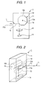
- Fig. 1 is a schematic diagram showing the construction of a first example of an image input device
- Fig. 2 is a perspective view showing the first example of an image input device.
- An image input device 1 shown in Fig. 1 is designed so that a mirror body 12, a lens 13 and a linear sensor 14 are provided in a housing 11.
- the housing 11 is formed of a light shielding material. It is designed in a rectangular parallelepiped shape, for example, and is provided at one surface thereof with a slender incidence window 11a for passing image pickup light L from the subject therethrough into the inside of the housing 11. As described later, the incidence window 11 a is formed so that the length direction thereof is substantially parallel to the length direction of the mirror body 12.
- the mirror body 12 is designed in a polygonal prism form, and all the side peripheral surfaces 12a thereof are formed of mirror faces (hereinafter the side peripheral surface 12a is referred to as the mirror face 12a).
- the mirror body 12 is disposed in the housing 11 so that the length direction thereof is substantially parallel to the length direction of the linear sensor 14 and the image pickup light L from the incidence window 11a is reflected from the mirror face 12a.
- Figs. 1 and 2 show a case where the mirror body 12 has an octagonal prism form and each mirror face 12a is flat.
- the center of the plane which is substantially perpendicular to the length direction of the mirror body 12, that is, the substantial centers of the bottom surfaces 12b at both sides of the side peripheral surfaces 12a of the mirror body 12 are supported by a shaft 15 so as to be rotatable in the housing 11 and thus the mirror body 12 autorotates around the shaft 15. Furthermore, a first driving circuit (not shown) for rotating the mirror body 12 is connected to the mirror body 12.
- the lens 13 projects the image pickup light L onto the linear sensor 14.
- it is fixedly disposed between the mirror body 12 and the linear sensor 14 so as to project the image pickup light L reflected from the mirror face 12a of the mirror body 12 onto the linear sensor 14.
- the linear sensor 14 has a function of taking the image pickup light L reflected from the mirror body 12 to subject it to photoelectric conversion and outputting electrical signals thus obtained as video signals (image pickup information).
- a semiconductor image pickup device such as an MOS (metal oxide semiconductor) type sensor, a CCD (charge coupled device) type sensor or the like.
- a white-and-black sensor or a color sensor may be used as the linear sensor 14 using such a semiconductor image pickup device, and a coloring system using a combination of an external color filter and a white-and-black sensor may be used.
- a color sensor a 3-line color linear sensor, a dot-sequential type color linear sensor, a multi-line color linear sensor, a TDI type linear sensor or the like may be used.
- a peripheral circuit for driving the linear sensor 14, a signal processing circuit for performing signal processing of image pickup information output from the linear sensor 14, a timing signal generating circuit for outputting a timing signal to the first driving circuit of the mirror body 12 and the peripheral circuit of the linear sensor 14, etc., which are not shown in the figure, are provided in the housing 11 in which the mirror body 12, the lens and the linear sensor 14 are accommodated.
- the image pickup light L from the subject is incident from the incidence window 12 of the housing 11, reflected from the mirror surface 12a of the mirror body 12, passed through the lens 13 and then projected onto and taken into the linear sensor 14.
- the image pickup light L is taken into the linear sensor 14 so that the direction of the light component L 1 incident from the subject to the mirror face 12a is continuously varied because the arrangement positions of the mirror body 12, the lens 13 and the linear sensor 14 are fixed.
- the image pickup light obtained as if the linear sensor 14 scans the subject that is, the two-dimensional image information can be obtained.
- the linear sensor 14 since the linear sensor 14 may be arranged so as to take the image pickup light L projected onto the linear sensor 14, the image pickup information can be obtained with no effect even when the precision of the arrangement position of the linear sensor 14 is low as compared with the conventional linear scan camera. Therefore, the manufacturing work is very easy and thus the productivity can be enhanced.
- the housing 11 can be designed in a small size and image pickup information can be input in a short time.
- the power consumption can be more reduced.
- the positional relationship between the subject and the image input device 1 is not fixed, but some degree of freedom is provided to the distance therebetween, two-dimensional image information can be obtained by targeting a three-dimensional space as a subject.
- the positional relationship between the subject and the image input device 1 is not fixed and the housing 11 can be miniaturized, so that a portable image input device 1 can be designed.
- the mirror body 12 has a polygonal prism form, after image pickup light L reflected from a mirror face 12a is obtained, a subsequent adjacent mirror face 12a provides image pickup light L in which the direction of the light component L 1 incident to the mirror face 12A continuously varies as in the case of the previous face mirror 12a.
- a linear sensor 14 which can provide an image having a higher resolution as compared with an image input device using an area sensor, that is, a so-called digital camera. Accordingly, if the subject is still, the two-dimensional information of the same subject is repetitively taken into the linear sensor 14, so that a higher resolution still image can be obtained.
- a two-dimensional image having the same level image quality can be obtained at a still lower cost than a conventional digital camera using an area sensor which must be manufactured at a high cost because a large number of pixels are needed to obtain an ultra-high resolution image. Furthermore, if the image input device 1 is manufactured substantially at the same cost as the digital camera using the area sensor, a higher-resolution image can be obtained. If the subject has a motion, two-dimensional image information having continuous motions of the subject can be obtained. Therefore, the moving picture of the two-dimensional image can be obtained.
- the lens 13 is provided between the mirror body 12 and the linear sensor 14.
- the lens 13 may be provided between the incidence window 11a and the mirror body 12 so that the image pickup light L from the subject is incident to the mirror face 12a of the mirror body 12 through the lens 13.
- the mirror body is designed in an octagonal prism form.
- the shape of the mirror body is not limited to the above example.
- the mirror body is designed in a polygonal prism form under the condition that the intersecting angle between adjacent mirror faces is set to a predetermined value in consideration of functions such as optical correction, etc.
- each mirror face of the mirror body is flat.
- each mirror face may be curved in consideration of correction elements such as optical correction, etc. If the optical correction, etc. are carried out by using the shape of the mirror body, no correction circuit is needed to perform the optical correction, so that the image input device can be further miniaturized and the productivity can be further enhanced. Furthermore, when the optical correction, etc. can be performed on the basis of the intersecting angle between the adjacent mirror faces although each mirror face of the mirror body is flat, or when no optical correction is needed, the manufacturing cost of the mirror body can be reduced.
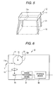
- FIG. 4A, 4B and Fig. 5 the same elements as the first embodiment are represented by the same reference numerals, and the description thereof is omitted.
- the difference of the image input device 2 of the second example from the first example resides in that support legs 21 which are expandable from the housing 11 to the outside to support the housing 11 are provided on one surface of the housing 11 on which the incidence window 11a is formed.
- the support legs 21 are designed in a rod form, and they are provided at four comers on one surface of the housing 11 on which the incidence window 11a is formed, for example. Furthermore, as shown in Fig. 4A, they are provided so as to be retractable into the housing 11.
- Each of the four support legs 21 is designed to expand and contract.
- the support legs 21 are expanded from the housing 11, and the housing 11 is arranged through the support legs 21 on a table (not shown) so that the incidence window 11a of the housing 11 faces the subject 10 such as an original, a photograph or the like which is put on the table.
- the image pickup light L from the subject 10 is taken into the linear sensor 14 through the incidence window 11a, the mirror face 12a of the mirror body 12 and the lens 13 while the mirror body 12 in the housing 11 is rotated (see Fig. 1), or the image pickup light L is taken into the linear sensor 14 through the incidence window 11a, the lens 13 and the mirror face 12a of the mirror body 12 (see Fig. 3), and the image pickup light L thus taken is converted to a video signal, thereby obtaining image pickup information of the subject 10 such as an original, a photograph or the like. That is, the image input device functions as a so-called image scanner.
- the support legs 21 can be retracted into the housing 11, and they are put together in compact size, thereby facilitating portability of the device. Furthermore, the degree of freedom is provided to the distance between the subject and the image input device 1 by retracting the support legs 21 into the housing 11 as in the case of the image input device 1 of the first example, and thus two-dimensional image information can be obtained by targeting a three-dimensional space as a subject. Therefore, the image input device 2 of the second example has a function as a portable image scanner and a function of obtaining a two-dimensional still image or moving picture by targeting a three-dimensional space as a subject.
- the support legs are retractable into the housing, however, they may be detachably mounted to the housing.
- the rod-shaped support legs are respectively mounted at the four comers.
- any mounting manner may be used insofar as the support legs are provided to the housing so that the housing can be stably supported and the image input operation is not disturbed.
- three rod-shaped support legs may be provided, or two inverted T-shaped support legs are disposed so as to face each other.
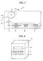
- FIG. 6 the same elements as the first example of Figs. 1 and 2 are represented by the same reference numerals, and the description thereof is omitted.
- the difference of the image input device 3 of the third example from the first example resides in that storage means 32 for storing image pickup information output from the linear sensor 14 is provided in the housing 11 while it is connected to the linear sensor 14. Furthermore, in this example, signal processing means 31 comprising a signal processing circuit for subjecting the image pickup information from the linear sensor 14 to predetermined signal processing is provided between the linear sensor 14 and the storage means 32, and the image pickup information which is subjected to the signal processing in the signal processing means 31 is stored in the storage means 32.
- the storage means 32 is used a semiconductor memory such as RAM or the like, a floppy disk, MO (magnet optical) disk, a magnetic tape, a compact disk or the like.
- the image input device 3 as described above is provided with the storage means 32, and thus a large amount of image pickup information can be accumulated. Therefore, when two-dimensional moving pictures are obtained, the output from the linear sensor 14 can be accumulated in the storage means 32 every mirror face 12a of the mirror body 12 (every scan), and thus the image input device is very effective. Furthermore, the image pickup information thus accumulated is corrected on the time axis and output from the storage means 32 to a monitor to display two-dimensional moving pictures on the monitor. If the rotating timing of the mirror body 12 can be controlled so that it is unnecessary to correct the time axis for the image pickup information output from the linear sensor 14 when moving pictures are obtained, the storage means 32 may be omitted.
- FIG. 7 A fourth example of an image input device will be described with reference to Fig. 7.
- the same elements as the third example are represented by the same reference numerals, and the description thereof is omitted.
- the difference of the image input device 4 of the fourth example from the third example resides in that an external interface 41 serving as communication means to communicate the image pickup information output from the linear sensor 14 to the outside is provided in the housing 11 so as to be connected to the linear sensor 14.
- the image pickup information from the linear sensor 14 is input to the external interface 41 through the signal processing means 31 and the storage means 32.
- the external interface 41 may be used a communication circuit having RS232, 1349, USB, IRDA and a portable telephone function, an originally-standardized interactive or unidirectional communication circuit or the like.
- the image input device 4 described above is provided with the external interface 41, and thus the image pickup information accumulated in the storage means 32 can be transmitted through the external interface 41 to the outside. Therefore, the image pickup information can be transferred from the storage means 32 through the external interface 41 to another storage medium or the like, so that the storage means 32 is allowed to store a large amount of information at all times. Furthermore, even at a remote place, an image input from the image input device 4 can be transmitted and viewed.
- the image input devices 1 to 4 of the above first to fourth examples may be provided with optical or electrical hand-movement correcting means for correcting the movement of hands.
- the optical hand-movement correcting means comprises a lens portion containing a lens 13 and an active prism installed in the lens 13, and a hand-movement detector.
- the hand-movement is corrected by varying the refraction of the image pickup light L through the lens portion in accordance with the detection of the hand-movement in the hand-movement detector.
- the electrical hand-movement correcting means comprises a linear sensor 14 having a broader image pickup area than the effective angle of view corresponding to the image pickup information, and a hand-movement detector. The effective angle of view is moved in accordance with the detection of the movement of hands to correct the movement of hands.
- FIG. 8 the same elements as the first example are represented by the same reference numerals, and the description thereof is omitted.
- the difference of the image input device 5 of this embodiment resides in that a plurality of illuminators 51 which are successively turned on to light up to the subject are provided in the housing 11.
- a number of illuminators 51 are arranged on one surface of the housing 11 on which the incidence window 11a is provided.
- each illuminator 51 comprises an electronic flash such as a xenon lamp or the like.
- a second driving circuit 52 serving as second driving means for successively turning on the illuminators 51 is provided in the housing 11.
- a first driving circuit 16 serving as first driving means for rotating the mirror body 12, a peripheral circuit 17 for driving the linear sensor 14, a second driving circuit 52 and a timing signal generating circuit (timing signal generating means) 53 for outputting timing signals to the first driving circuit 16, the peripheral circuit 17 and the second driving circuit 52 are provided in the housing 11.
- the timing signal generating circuit 53 outputs the timing signals to the first driving circuit 16 and the second driving circuit 17 so that the illuminators 51 are turned on at a predetermined timing with respect to the rotation of the mirror body 12.
- the first driving circuit 16 and the second driving circuit 17 serve to rotate the mirror body 12 and turn on the illuminators 51.
- the timing signal generating circuit 53 is supplied with a vertical synchronous signal (hereinafter referred to as VD signal).
- VD signal a vertical synchronous signal
- the timing signal generating circuit 53 outputs to the second driving circuit 52 a trigger pulse which is a timing signal for turning on the illuminators 51 in synchronism with the VD signal.
- the timing signal generating circuit 53 has a function of outputting to the first driving circuit 16 a timing signal for rotating the mirror body 12 in ) synchronism with the VD signal.
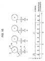
- Fig. 10 is a timing chart showing an example of the timing relationship between the VD signal and the trigger pulse output to the second driving circuit 52.
- the trigger pulse is output from the timing signal generating circuit 53 to the second driving circuit 52 substantially simultaneously with input of the VD signal to the timing signal generating circuit 53.
- the timing signal is output to the first driving circuit 16 so that the mirror body 12 is rotated at such a speed that the reflection of the image pickup light L is started and ended at one mirror face 12a of the mirror body 12, that is, one scan operation is completed during the time period from input of a VD signal until input of a next VD signal. Furthermore, representing the start time point of the reflection of the image pickup light L at a mirror face 12a by t 1 and representing the start time point of the image pickup light L at an adjacent mirror face 12a by t 3 , a trigger pulse is output to the second driving circuit 52 at an equal interval, for example at five times between t 1 and t 3 to successively turn on the illuminators 51.
- a plurality of illuminators 51 which are successively turned on to light up to the subject are provided in the housing 11, and the illuminators 51 can be successively turned on when image pickup light L (of one scan) reflected from a mirror face is obtained.
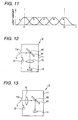
- the light amount of each of the illuminators 51 a to e varies like a Gaussian distribution as shown in Fig. 11, but the sum of the light amount can be set to a substantially fixed value by successively turning on the illuminators during one scan period (the sum is indicated by one-dotted chain line in Fig. 11).
- light can be substantially uniformly irradiated to the subject during one scan period.
- the accumulation time of the image pickup light L to be taken per scan is shorter as compared with the area sensor, the image pickup light L having a large accumulation amount can be obtained. Therefore, information of a clear and uniform two-dimensional image can be obtained under such an environment that a subject serving as a target is short of light amount, for example, under a dark three-dimensional space such as night or the like.
- the illuminators, the first driving means, the second driving means, the timing signal generating means, etc. are installed into the image input device 1 of the first example, thereby constructing the image input device 5.
- the illuminators, etc. may be installed into the image input device 1 of the modification shown in Fig. 3, the image input device 2 of the second example, the image input device 3 of the third example or the image input device 4 of the fourth example, thereby constructing the image input device which can provide clear and uniform two-dimensional image information even under a three-dimensional space which lacks light amount.
- the illuminators 51, etc. may be installed to an image input device 6 having a flat-plate type mirror body 61 as shown in a first modification of Fig. 12 and a second modification of Fig. 13.
- This mirror body 61 is formed of mirror face on one surface or both the surfaces thereof, and a shaft 62 is formed along the mirror face within the thickness of the mirror body 61.
- the mirror body 61 is supported by the shaft 62, and rotatable or swingable around the shaft 62.
- the incidence window 11a is formed so that the length direction thereof is substantially parallel to the shaft 62 of the mirror body 61. It is needless to say that clear and uniform two-dimensional image information can be obtained by even such an image input device 6.
- plural illuminators which are successively turned on to light up to the subject are provided in the housing in which the mirror body and the linear sensor are accommodated, and when image pickup light (of one scan) reflected from a mirror face is obtained, the illuminators are successively turned on to irradiate uniform light to the subject. Therefore, clear and uniform two-dimensional image information can be obtained even under such an environment that a target subject lacks light amount, for example, under a dark three-dimensional space such as night or the like.
Landscapes
- Engineering & Computer Science (AREA)
- Multimedia (AREA)
- Signal Processing (AREA)
- Physics & Mathematics (AREA)
- General Physics & Mathematics (AREA)
- Optics & Photonics (AREA)
- Image Input (AREA)
- Facsimile Scanning Arrangements (AREA)
- Transforming Light Signals Into Electric Signals (AREA)
- Studio Devices (AREA)
Claims (8)
- Abtastbild-Eingabeeinrichtung, welche aufweist:ein Gehäuse (11), welches ein schlankes Einfallsfenster (11a) hat, um Bildabtastlicht von einem Gegenstand in das Gehäuse (11) durchzulassen;einen Spiegelkörper (12), der drehbar oder verschwenkbar im Gehäuse (11) vorgesehen ist, der Spiegelflächen (12a) aufweist, um das Bildabtastlicht vom Einfallsfenster (11a) zu reflektieren; undeinen Linearsensor (14), welcher im Gehäuse (11) angeordnet ist und der das Bildabtastlicht, welches vom Spiegelkörper (12) reflektiert wird, nimmt, um das Bildabtastlicht foto-elektrischer Umsetzung zu unterwerfen, und dadurch gekennzeichnet, dass die Bildeingabeeinrichtung außerdem aufweist:mehrere Elektronenblitz-Beleuchtungseinrichtungen (51), welche im Gehäuse (11) vorgesehen sind, und eine Einrichtung, um die elektronischen Blitz-Beleuchtungseinrichtungen nacheinander einzuschalten, um den Gegenstand im Wesentlichen gleichförmig während einer Abtastperiode zu bestrahlen.
- Bildeingabeeinrichtung nach Anspruch 1, wobei der Spiegelkörper (12) zu einer polygonalen Prismenform ausgebildet ist und auf allen seinen seitlichen Umfangsflächen aus den Spiegelflächen (12a) gebildet ist und so angeordnet ist, dass seine Längsrichtung im Wesentlichen parallel zur Längsrichtung des Linearsensors (14) ist und so vorgesehen ist, um um die Mitte (15) der Ebene drehbar zu sein, welche im Wesentlichen senkrecht zur Längsrichtung des Spiegelkörpers (12) ist, und wobei das Einfallsfenster (11a) so gebildet ist, dass seine Längsrichtung im Wesentlichen parallel zur Längsrichtung des Spiegelkörpers (12) ist.
- Bildeingabeeinrichtung nach Anspruch 1, wobei der Spiegelkörper (12) in der Form einer flachen Platte ausgebildet ist, wobei eine Fläche oder beide Flächen davon aus den Spiegelflächen (12a) gebildet sind, und eine Welle (15) längs der Spiegelflächen (12a) gebildet ist, die innerhalb des Spiegelkörpers (12) angeordnet ist, so dass der Spiegelkörper (12) um die Welle (15) drehbar oder verschwenkbar ist, und wobei das Einfallsfenster (11a) so ausgebildet ist, dass die Längsrichtung im Wesentlichen parallel zur Welle (15) des Spiegelkörpers (12) ist.
- Bildeingabeeinrichtung nach Anspruch 1, welche außerdem aufweist:eine erste Ansteuereinrichtung (16), um den Spiegelkörper (12) zu drehen oder zu verschwenken;eine zweiten Ansteuereinrichtung (52), um die mehreren Beleuchtungseinrichtungen (51) nacheinander einzuschalten; undeine Zeitgabesignal-Erzeugungseinrichtung (53), um Zeitgabesignale an die erste Ansteuereinrichtung (16) und die zweite Ansteuereinrichtung (52) auszugeben, so dass die Beleuchtungseinrichtungen (51) nacheinander in einem vorher festgelegten Zeitablauf in bezug auf die Dreh- oder Schwenkbewegung des Spiegelkörpers (12) eingeschaltet werden.
- Bildeingabeeinrichtung nach Anspruch 1, welche außerdem Stützfüße (21) aufweist, welche an der Bildungsseite des Einfallsfensters (11a) des Gehäuses (11) gebildet sind, die sich vom Gehäuse (11) zur Außenseite erstrecken und das Gehäuse (11) stützen, wobei die Stützfüße (21) so vorgesehen sind, dass sie in das Gehäuse (11) zurückziehbar sind oder am Gehäuse (11) lösbar befestigt sind.
- Bildeingabeeinrichtung nach Anspruch 1, welche außerdem eine Speichereinrichtung (32) aufweist, um Bildabtastinformation, welche vom Linearsensor (14) ausgegeben wird, zu speichern.
- Bildeingabeeinrichtung nach Anspruch 1, welche außerdem eine Kommunikationseinrichtung (41) aufweist, um die Bildabtastinformation, welche vom Linearsensor (14) ausgegeben wird, nach außen hin mitzuteilen.
- Bildeingabeeinrichtung nach Anspruch 1, wobei der Linearsensor (14) durch ein Halbleiter-Bildabtastelement gebildet ist.
Applications Claiming Priority (3)
| Application Number | Priority Date | Filing Date | Title |
|---|---|---|---|
| JP10091078A JPH11289495A (ja) | 1998-04-03 | 1998-04-03 | 画像入力装置 |
| JP9107898 | 1998-04-03 | ||
| EP99400818A EP0948196B1 (de) | 1998-04-03 | 1999-04-02 | Bildeingabevorrichtung |
Related Parent Applications (1)
| Application Number | Title | Priority Date | Filing Date |
|---|---|---|---|
| EP99400818A Division EP0948196B1 (de) | 1998-04-03 | 1999-04-02 | Bildeingabevorrichtung |
Publications (2)
| Publication Number | Publication Date |
|---|---|
| EP1255151A1 EP1255151A1 (de) | 2002-11-06 |
| EP1255151B1 true EP1255151B1 (de) | 2004-06-16 |
Family
ID=14016485
Family Applications (2)
| Application Number | Title | Priority Date | Filing Date |
|---|---|---|---|
| EP99400818A Expired - Lifetime EP0948196B1 (de) | 1998-04-03 | 1999-04-02 | Bildeingabevorrichtung |
| EP02077920A Expired - Lifetime EP1255151B1 (de) | 1998-04-03 | 1999-04-02 | Bildeingabevorrichtung |
Family Applications Before (1)
| Application Number | Title | Priority Date | Filing Date |
|---|---|---|---|
| EP99400818A Expired - Lifetime EP0948196B1 (de) | 1998-04-03 | 1999-04-02 | Bildeingabevorrichtung |
Country Status (6)
| Country | Link |
|---|---|
| US (1) | US6917385B1 (de) |
| EP (2) | EP0948196B1 (de) |
| JP (1) | JPH11289495A (de) |
| CN (1) | CN1183478C (de) |
| DE (2) | DE69918190T2 (de) |
| TW (1) | TW420944B (de) |
Families Citing this family (9)
| Publication number | Priority date | Publication date | Assignee | Title |
|---|---|---|---|---|
| TWI231050B (en) * | 2003-09-29 | 2005-04-11 | Primax Electronics Ltd | Moveable mirror module for an image capturing apparatus capable of taking multi angle pictures |
| FR2867645A1 (fr) * | 2004-03-15 | 2005-09-16 | Jean Rene Eude | Dispositif pour creer une image numerique 2d ou 3d pour une camera numerique 2d, un appareil photo numerique ou une camera 3d. |
| US7567287B2 (en) * | 2006-09-20 | 2009-07-28 | Sony Ericsson Mobile Communications Ab | Rotating prism for a digital camera in a portable mobile communication device |
| JP4653123B2 (ja) * | 2007-01-09 | 2011-03-16 | 富士フイルム株式会社 | 画像取得装置および画像取得方法 |
| CN102045481B (zh) * | 2009-10-10 | 2013-03-20 | 上海祥网瑞电子科技有限公司 | 带切换镜片快速平面图像采集器 |
| US20150169046A1 (en) * | 2013-12-13 | 2015-06-18 | Honeywell International Inc. | Line scan camera eye tracking system and method |
| DE102015215840B4 (de) * | 2015-08-19 | 2017-03-23 | Fraunhofer-Gesellschaft zur Förderung der angewandten Forschung e.V. | Multiaperturabbildungsvorrichtung, Abbildungssystem und Verfahren zum Bereitstellen einer Multiaperturabbildungsvorrichtung |
| CA3017349C (en) * | 2016-03-10 | 2021-08-31 | Visbit Inc. | Time multiplexing programmable field of view imaging |
| JPWO2020066402A1 (ja) * | 2018-09-25 | 2021-08-30 | 株式会社小糸製作所 | 光照射装置 |
Family Cites Families (23)
| Publication number | Priority date | Publication date | Assignee | Title |
|---|---|---|---|---|
| US3137532A (en) * | 1962-08-29 | 1964-06-16 | Tyll Charles | Instrument cases |
| JPS6337772A (ja) | 1986-08-01 | 1988-02-18 | Nec Home Electronics Ltd | 画像入力装置 |
| JPH0193258A (ja) | 1987-10-05 | 1989-04-12 | Casio Comput Co Ltd | 画像読取装置 |
| JPH04203915A (ja) | 1990-11-30 | 1992-07-24 | Hitachi Ltd | 大視野画像入力方法および装置 |
| CA2065482A1 (en) * | 1991-04-11 | 1992-10-12 | Akira Inoue | Method and apparatus for measuring a coating state |
| JPH06197250A (ja) | 1992-02-21 | 1994-07-15 | Hitachi Ltd | ビデオカメラ |
| US5748236A (en) * | 1993-12-10 | 1998-05-05 | Nikon Corporation | Color mixing prevention and color balance setting device and method for a field-sequential color television camera |
| US5668631A (en) * | 1993-12-20 | 1997-09-16 | Minolta Co., Ltd. | Measuring system with improved method of reading image data of an object |
| US5671080A (en) * | 1993-12-22 | 1997-09-23 | Olympus Optical Co., Ltd. | Optical system scanning with a mirror for electronic image pickup apparatus |
| US5625183A (en) | 1994-06-15 | 1997-04-29 | Nec Corporation | Rotary mirror scanner unit having optical angular displacement sensor |
| DE4428202A1 (de) * | 1994-08-09 | 1996-02-15 | Deutsche Forsch Luft Raumfahrt | Vorrichtung zur Erzeugung eines Bildes |
| JPH0870407A (ja) | 1994-08-26 | 1996-03-12 | Toshiba Corp | 撮像装置 |
| JPH08274956A (ja) | 1995-03-30 | 1996-10-18 | Nec Corp | イメージスキャナ |
| JPH09307676A (ja) * | 1996-03-14 | 1997-11-28 | Nikon Corp | 画像読取装置 |
| JP3397580B2 (ja) * | 1996-06-07 | 2003-04-14 | ペンタックス株式会社 | 遠隔操作可能なスキャナ |
| US5993077A (en) * | 1996-08-05 | 1999-11-30 | Jones; Steven P. | Stand assembly for an optical device |
| US6426776B1 (en) * | 1997-03-18 | 2002-07-30 | Minolta Co., Ltd. | Apparatus for and method of photographing using scanning techniques |
| JPH10290321A (ja) * | 1997-04-14 | 1998-10-27 | Nikon Corp | 画像読取装置および透過原稿アダプタ |
| JPH11243471A (ja) * | 1998-02-26 | 1999-09-07 | Brother Ind Ltd | カラー読取装置および記憶媒体 |
| US6462772B1 (en) * | 1998-12-23 | 2002-10-08 | Eastman Kodak Company | Method of calibrating image scanning apparatus of a photographic film scanner |
| US20030183746A1 (en) * | 2002-04-02 | 2003-10-02 | Pao-Jung Chen | High speed single-linear three-color CIS image sensing array |
| KR100449729B1 (ko) * | 2002-06-29 | 2004-09-22 | 삼성전자주식회사 | 주사 광학장치 |
| JP2004109204A (ja) * | 2002-09-13 | 2004-04-08 | Pentax Corp | 走査光学系 |
-
1998
- 1998-04-03 JP JP10091078A patent/JPH11289495A/ja active Pending
-
1999
- 1999-04-01 US US09/283,233 patent/US6917385B1/en not_active Expired - Fee Related
- 1999-04-01 CN CNB991059182A patent/CN1183478C/zh not_active Expired - Fee Related
- 1999-04-01 TW TW088105198A patent/TW420944B/zh not_active IP Right Cessation
- 1999-04-02 DE DE69918190T patent/DE69918190T2/de not_active Expired - Lifetime
- 1999-04-02 DE DE69913598T patent/DE69913598T2/de not_active Expired - Lifetime
- 1999-04-02 EP EP99400818A patent/EP0948196B1/de not_active Expired - Lifetime
- 1999-04-02 EP EP02077920A patent/EP1255151B1/de not_active Expired - Lifetime
Also Published As
| Publication number | Publication date |
|---|---|
| TW420944B (en) | 2001-02-01 |
| EP0948196A3 (de) | 2000-04-19 |
| EP0948196B1 (de) | 2003-12-17 |
| CN1237744A (zh) | 1999-12-08 |
| DE69918190T2 (de) | 2005-07-07 |
| DE69918190D1 (de) | 2004-07-22 |
| US6917385B1 (en) | 2005-07-12 |
| DE69913598T2 (de) | 2004-10-07 |
| EP0948196A2 (de) | 1999-10-06 |
| CN1183478C (zh) | 2005-01-05 |
| DE69913598D1 (de) | 2004-01-29 |
| JPH11289495A (ja) | 1999-10-19 |
| EP1255151A1 (de) | 2002-11-06 |
Similar Documents
| Publication | Publication Date | Title |
|---|---|---|
| US5253071A (en) | Method and apparatus for stabilizing an image produced in a video camera | |
| CN101690162B (zh) | 图像捕捉设备及方法 | |
| JP2753541B2 (ja) | 静止画撮像装置 | |
| EP1255151B1 (de) | Bildeingabevorrichtung | |
| US4667255A (en) | Electronic camera employing a solid-state image sensor | |
| JPH07174536A (ja) | 3次元形状測定装置 | |
| JPH0813088B2 (ja) | 画像読取装置 | |
| KR100216232B1 (ko) | 촬상장치 | |
| JP2002196438A (ja) | 広角撮像装置 | |
| US4901157A (en) | Line scan image scanner for use with reflective originals and transparent films | |
| US5084756A (en) | Apparatus operable as a viewer or image scanner | |
| JP3072846B2 (ja) | リモートセンシング装置と撮像カメラ装置 | |
| JPH03276981A (ja) | 固体撮像装置 | |
| JPH046308B2 (de) | ||
| EP0932296A2 (de) | Bildlesegerät | |
| JPS6342614Y2 (de) | ||
| JPS5691582A (en) | Image pickup device | |
| JP2649733B2 (ja) | 画像入力装置 | |
| JPH09214991A (ja) | 撮像装置 | |
| JPH1023321A (ja) | 画像入力装置 | |
| JPH08307657A (ja) | 画像入力装置 | |
| JPH01229573A (ja) | 電子スチルカメラ | |
| WO1996027980A1 (en) | High precision electronic camera and its control method | |
| JPH1093850A (ja) | 撮像装置 | |
| JPH07143378A (ja) | 撮像装置 |
Legal Events
| Date | Code | Title | Description |
|---|---|---|---|
| PUAI | Public reference made under article 153(3) epc to a published international application that has entered the european phase |
Free format text: ORIGINAL CODE: 0009012 |
|
| AC | Divisional application: reference to earlier application |
Ref document number: 948196 Country of ref document: EP |
|
| AK | Designated contracting states |
Kind code of ref document: A1 Designated state(s): DE FR GB |
|
| 17P | Request for examination filed |
Effective date: 20030424 |
|
| AKX | Designation fees paid |
Designated state(s): DE FR GB |
|
| GRAP | Despatch of communication of intention to grant a patent |
Free format text: ORIGINAL CODE: EPIDOSNIGR1 |
|
| GRAS | Grant fee paid |
Free format text: ORIGINAL CODE: EPIDOSNIGR3 |
|
| GRAA | (expected) grant |
Free format text: ORIGINAL CODE: 0009210 |
|
| AC | Divisional application: reference to earlier application |
Ref document number: 0948196 Country of ref document: EP Kind code of ref document: P |
|
| AK | Designated contracting states |
Kind code of ref document: B1 Designated state(s): DE FR GB |
|
| REG | Reference to a national code |
Ref country code: GB Ref legal event code: FG4D |
|
| REF | Corresponds to: |
Ref document number: 69918190 Country of ref document: DE Date of ref document: 20040722 Kind code of ref document: P |
|
| ET | Fr: translation filed | ||
| PLBE | No opposition filed within time limit |
Free format text: ORIGINAL CODE: 0009261 |
|
| STAA | Information on the status of an ep patent application or granted ep patent |
Free format text: STATUS: NO OPPOSITION FILED WITHIN TIME LIMIT |
|
| 26N | No opposition filed |
Effective date: 20050317 |
|
| REG | Reference to a national code |
Ref country code: GB Ref legal event code: 746 Effective date: 20091130 |
|
| PGFP | Annual fee paid to national office [announced via postgrant information from national office to epo] |
Ref country code: GB Payment date: 20140422 Year of fee payment: 16 |
|
| PGFP | Annual fee paid to national office [announced via postgrant information from national office to epo] |
Ref country code: FR Payment date: 20140422 Year of fee payment: 16 Ref country code: DE Payment date: 20140418 Year of fee payment: 16 |
|
| REG | Reference to a national code |
Ref country code: DE Ref legal event code: R119 Ref document number: 69918190 Country of ref document: DE |
|
| GBPC | Gb: european patent ceased through non-payment of renewal fee |
Effective date: 20150402 |
|
| PG25 | Lapsed in a contracting state [announced via postgrant information from national office to epo] |
Ref country code: GB Free format text: LAPSE BECAUSE OF NON-PAYMENT OF DUE FEES Effective date: 20150402 Ref country code: DE Free format text: LAPSE BECAUSE OF NON-PAYMENT OF DUE FEES Effective date: 20151103 |
|
| REG | Reference to a national code |
Ref country code: FR Ref legal event code: ST Effective date: 20151231 |
|
| PG25 | Lapsed in a contracting state [announced via postgrant information from national office to epo] |
Ref country code: FR Free format text: LAPSE BECAUSE OF NON-PAYMENT OF DUE FEES Effective date: 20150430 |