EP1253278A2 - Vorrichtung zur veränderbaren Gestaltung einer Unterkonstruktion - Google Patents
Vorrichtung zur veränderbaren Gestaltung einer Unterkonstruktion Download PDFInfo
- Publication number
- EP1253278A2 EP1253278A2 EP02008707A EP02008707A EP1253278A2 EP 1253278 A2 EP1253278 A2 EP 1253278A2 EP 02008707 A EP02008707 A EP 02008707A EP 02008707 A EP02008707 A EP 02008707A EP 1253278 A2 EP1253278 A2 EP 1253278A2
- Authority
- EP
- European Patent Office
- Prior art keywords
- running rail
- substructure
- running
- decorative element
- clamp holder
- Prior art date
- Legal status (The legal status is an assumption and is not a legal conclusion. Google has not performed a legal analysis and makes no representation as to the accuracy of the status listed.)
- Withdrawn
Links
Images




Classifications
-
- A—HUMAN NECESSITIES
- A47—FURNITURE; DOMESTIC ARTICLES OR APPLIANCES; COFFEE MILLS; SPICE MILLS; SUCTION CLEANERS IN GENERAL
- A47H—FURNISHINGS FOR WINDOWS OR DOORS
- A47H99/00—Subject matter not provided for in other groups of this subclass
-
- E—FIXED CONSTRUCTIONS
- E06—DOORS, WINDOWS, SHUTTERS, OR ROLLER BLINDS IN GENERAL; LADDERS
- E06B—FIXED OR MOVABLE CLOSURES FOR OPENINGS IN BUILDINGS, VEHICLES, FENCES OR LIKE ENCLOSURES IN GENERAL, e.g. DOORS, WINDOWS, BLINDS, GATES
- E06B9/00—Screening or protective devices for wall or similar openings, with or without operating or securing mechanisms; Closures of similar construction
- E06B9/02—Shutters, movable grilles, or other safety closing devices, e.g. against burglary
- E06B9/04—Shutters, movable grilles, or other safety closing devices, e.g. against burglary of wing type, e.g. revolving or sliding
-
- G—PHYSICS
- G09—EDUCATION; CRYPTOGRAPHY; DISPLAY; ADVERTISING; SEALS
- G09F—DISPLAYING; ADVERTISING; SIGNS; LABELS OR NAME-PLATES; SEALS
- G09F11/00—Indicating arrangements for variable information in which the complete information is permanently attached to a movable support which brings it to the display position
-
- G—PHYSICS
- G09—EDUCATION; CRYPTOGRAPHY; DISPLAY; ADVERTISING; SEALS
- G09F—DISPLAYING; ADVERTISING; SIGNS; LABELS OR NAME-PLATES; SEALS
- G09F7/00—Signs, name or number plates, letters, numerals, or symbols; Panels or boards
- G09F7/18—Means for attaching signs, plates, panels, or boards to a supporting structure
Definitions
- the invention relates to a device for the changeable design of a Substructure, such as a wall made of masonry, glass or the like, with at least one running rail arranged on the substructure, on which a sliding element is guided in a sliding or rolling manner.
- a Substructure such as a wall made of masonry, glass or the like
- the multi-part Execution, in particular of such rail clamp holders are overrun from the roller carriage of a sliding door system to one More expensive to manufacture the above-mentioned rail clamp holders and requires high precision, especially in the field of Track holder of the track clamp holder to ensure a backlash-free Storage of the running rail in the running rail holder of the running rail clamp holder to ensure.
- different distances given a support or support bar to a substructure, especially a wall can with the known devices can not be compensated.
- stoppers are used for the displacement of the sliding elements (see page 3/01 of the aforementioned brochure), the running track encompassing cylindrical part is slotted, so that the aforementioned Stopper by means of Allen screws reaching through the slotted part can be braced with the track. Stick to it the Allen screws that are inevitably turned towards the viewer are visible
- the object of the invention is a device for changeable design to create a substructure, in particular a wall, with which, based on the viewer, on the one hand the optical design of a Wall is changeable and with that on the other hand within a room prevailing lighting conditions can be varied. It should be in optical attractively given multiple design options his. Means are also proposed in an embodiment of the invention be what advantageous technical designs to solve the task set. This applies in particular on the design of the individual sliding elements, the training of the Roller carriage, the formation of the running track with the substructure connecting clamp holder and the design of the stopper.
- the length of the running rail is at least twice the width of the sliding element, the sliding element consisting of a plate-like flat, rigid, decorative element.
- the plate-like decorative element that is slidably guided on the running rail can alternatively be made of transparent material, for example glass or plastic or - if in one that forms the substructure Wall windows are arranged - completely or partially translucent be trained, d. H. for example made of tinted or painted Glass exist.
- the decorative element can be made of consist of an image, d. H. the positioning of an image relative to one Wall can be varied with negligible effort, with several Decorative elements of any design in a side-by-side arrangement can be arranged.
- Such a system is suitable especially for sales rooms or galleries. When used in Galleries can display different exhibits using suitable frames reproduced and replaced.
- the decorative elements are preferably suspended by means of a roller carriage guided on a running rail, in one embodiment the Arrangement of the running rails on the substructure several running rails spaced one above the other and running parallel to one another can be arranged and each decorative element at least two tracks is guided. This measure can be the more reliable Serve guidance or a lifting of the decorative element from the Counteract leadership. Of course it is also possible to use only one track to use.
- the substructure several rails spaced one above the other, parallel to each other and at different distances from the substructure to be arranged in such a way that decorative elements run on the running rails movable with mutual overlap on the running rails are.
- the spatially offset arrangement the decorative elements relative to the substructure have special effects achieve, especially when it comes to partially transparent decorative elements is.
- the rails do not have to be be arranged horizontally; the invention also includes the application diagonally or vertically running rails with guided Decorative elements, it being only necessary to to assign respective roller carriages easier holding elements that the roller carriages or the decorative element in the desired position jam the guide rail. Alternatively, you can do this descriptive stopper can be used.
- the running track is characterized by the fact that it has a roller bearing and has a support or guide roller receiving bearing block whose end face facing away from the support or guide roller is a clamping element for the frictional clamping of the decorative element is arranged.
- the clamping element is preferably conical and by means of a clamping screw encompassing the clamping element screwed to the bearing block.
- the clamp holder should be designed so that construction tolerances, d. H. - over the length of one Track seen - different distances between the substructure and the respective clamp holder with a special one Design of the clamp holder can be recognized and compensated.
- the Clamp holder between one connected to the substructure Fastening member and the running track receptacle opposite the fastening member distance-adjustable adjustment bearing on which the Track support is supported.
- the fastener connected to the substructure is preferred formed as a pot-like mounting bush, which with your The bottom of the pot rests on the substructure, so that the adjustment bearing with a complementary external thread in an internal thread of the mounting bush can be rotatably supported.
- the wall of the pot-like Fastening bush on an external thread on which by means of a complementary Internal thread a screw cap be screwed on can.
- the one to limit the displacement of a decorative element Stopper arranged on the running rail encloses the running rail a one-piece cylindrical sleeve, in a stop leg of the stopper has a diagonal hole open against the running rail for the Inclusion of a grub screw that braces the stopper with the running rail is arranged.
- This embodiment enables the waiver to a slotted version of the one enclosing the running rail Sleeve of the stopper and an arrangement of the clamping process Screw such that it is not distracting to the viewer is.
- FIGS. 1, 1a, 1b one is the substructure 1 forming wall 2 shown on the indicated side walls 8 connect.
- On the wall 2 are an upper rail 3 and a lower track 3 'arranged on which by means of roller carriages (see Figure 1a, 1b) sliding elements 4 and 4 '(see Figure 5) are performed hereinafter referred to as decorative elements 5.
- the decorative elements 5 are in the embodiment of Figure 1 and 1a as Images, in the exemplary embodiment 1b as completely or partially translucent or completely transparent glass panes.
- the decorative elements 5 are movable on the rails 3 and 3 'and for example suitable to cover the windows labeled 7. From the aforementioned The figure is also the arrangement of the track with the Wall 2 connecting clamp holder 15 and the arrangement of the stoppers 28th recognizable.
- Figure 2 shows accordingly Section A-A according to Figure 1, where both roller carriages 6 on the clamp holders 15 rest.
- FIG. 3 shows the section A-A to FIG. 1, the decorative element 5 is hanging only on the upper rail 3, while figure 5 shows the section A-A according to FIG. 1b, consequently the upper roller carriage 6 of the upper track 3 rests, while the lower roller carriage 6 understands the running rail 3 'from below in order to lift the To prevent decorative element 5.
- FIG. 4 shows an alternative to the roller support according to FIG. 1a or Figure 3; here is another running rail above the running rail 3 3 "arranged, the rails 3 and 3" spaced one above the other, parallel to each other and at different distances from the Substructure 1 are arranged in such a way that the to the Running rails 3 and 3 "guided decorative elements 5 with mutual Cover on the rails 3 and 3 "can be moved.
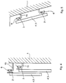
- FIG. 7 shows the section C-C through the roller carriage 6.
- the roller carriage 6 has a bearing block 11, on which the actual one via a roller bearing 9 Support or guide roller 10 is supported.
- a Clamping element 13 At which the carrying or Guide roller 10 facing end face 12 of the bearing block 11 is a Clamping element 13 for the frictional clamping of the one in FIG. 7 Decorative element 5, not shown, arranged.
- the clamping element 13 is conical and by means of a clamping element 13 comprehensive clamping screw 14 screwed to the bearing block 11.
- Figure 9 shows the section D-D through the stopper 28 of Figure 8. It can be seen that the stopper 28, the rail 3, 3 or not shown 3 "encloses with a one-piece cylindrical sleeve 29, in one Stop leg 30 of the stopper 28 against the not shown Running track open diagonal bore 31 is arranged. In the diagonal hole 31, a grub screw 32 can be screwed in, by means of Stopper 28 can be clamped to the running rail 3, 3 ', 3 ".
- Figure 10 shows a section through the connectable to the substructure 1 Clamp holder 15.
- the clamp holder 15 has a fastening member for this purpose 16, which is designed as a pot-like fastening bushing 19 and rests with its pot bottom on the substructure 1.
- the wall 24 of the fastening member 16 has an internal thread 22, into which an adjustment bearing 18 by means of an assigned external thread 21 can be screwed in. After screwing the fastener 16 by means of the mounting screw 33 to the substructure 1, the adjustment bearings 18 are so aligned that their adjustment surfaces 23 are aligned.
- the union bell designated by 26 is 27 by means of its internal thread can be screwed onto the external thread 25 of the fastening element 16, wherein the track receptacle 17 due to the abutment of its sleeve-shaped Extension is positioned exactly on the adjustment surface 23.
Landscapes
- Engineering & Computer Science (AREA)
- Physics & Mathematics (AREA)
- General Physics & Mathematics (AREA)
- Theoretical Computer Science (AREA)
- Structural Engineering (AREA)
- Architecture (AREA)
- Civil Engineering (AREA)
- Support Devices For Sliding Doors (AREA)
- Types And Forms Of Lifts (AREA)
Abstract
Description
- Die Figuren 1, 1a, 1b:
- zeigen in teilweiser perspektivischer Darstellung die Anordnung verschiedener Dekorationselemente unter Verwendung verschiedener Rollenführungen an einer Wand.
- Die Figuren 2 bis 5:
- zeigen entsprechende schematische Querschnitte mit den jeweils zugeordneten Rollenführungen entsprechend den Figuren 1, 1a, 1b.
- Die Figuren 6 und 7:
- zeigen in Draufsicht und im Schnitt einen Rollenwagen.
- Die Figuren 8 und 9:
- zeigen in Draufsicht und im Schnitt einen Stopper.
- Die Figur 10:
- zeigt im Schnitt einen Klemmhalter.
- 1
- Unterkonstruktion
- 2
- Wand
- 3
- Laufschiene
- 3'
- Laufschiene
- 3"
- Laufschiene
- 4
- Schiebeelement
- 4'
- Schiebeelement
- 5
- Dekorationselement
- 6
- Rollenwagen
- 7
- Fenster
- 8
- Seitenwände
- 9
- Rollenlager
- 10
- Trag- oder Führungsrolle
- 11
- Lagerbock
- 12
- Stirnfläche
- 13
- Klemmelement
- 14
- Klemmschraube
- 15
- Klemmhalter
- 16
- Befestigungsglied
- 17
- Laufschienenaufnahme
- 18
- Justierlager
- 19
- topfartige Befestigungsbuchse
- 20
- Topfboden
- 21
- Außengewinde
- 22
- Innengewinde
- 23
- Justierfläche
- 24
- Wandung
- 25
- Außengewinde
- 26
- Überwurfglocke
- 27
- Innengewinde
- 28
- Stopper
- 29
- zylindrische Hülse
- 30
- Anschlagsschenkel
- 31
- Diagonalbohrung
- 32
- Madenschraube
- 33
- Befestigungsschraube
- 34
- hülsenförmiger Fortsatz
Claims (17)
- Vorrichtung zur veränderbaren Gestaltung einer Unterkonstruktion (1), wie einer Wand (2) aus Mauerwerk, Glas oder dergleichen, mit wenigstens einer an der Unterkonstruktion (1) angeordneten Laufschiene (3, 3', 3"), an der ein Schiebeelement (4, 4') gleitend oder rollend geführt ist, dadurch gekennzeichnet, dass die Länge der Laufschiene (3, 3', 3") mindestens die doppelte Breite des Schiebeelementes (4, 4') aufweist und das Schiebeelement (4, 4') aus einem plattenartig flächigen, in sich starren, Dekorationselement (5) besteht.
- Vorrichtung nach Anspruch 1, dadurch gekennzeichnet, dass das Dekorationselement (5) aus durchsichtigem Material besteht.
- Vorrichtung nach Anspruch 1, dadurch gekennzeichnet, dass das Dekorationselement (5) ganz oder teilweise durchscheinend ausgebildet ist.
- Vorrichtung nach Anspruch 1, dadurch gekennzeichnet, dass das Dekorationselement (5) aus einem Bild besteht.
- Vorrichtung nach einem der Ansprüche 1 bis 4, dadurch gekennzeichnet, dass an einer Laufschiene (3, 3', 3") mehrere Dekorationselemente (5) in Nebeneinander-Anordnung angeordnet sind.
- Vorrichtung nach einem der Ansprüche 1 bis 5 , dadurch gekennzeichnet, dass das Dekorationselement (5) mittels eines Rollenwagens (6) hängend an einer Laufschiene (3) geführt ist.
- Vorrichtung nach einem der Ansprüche 1 bis 6, dadurch gekennzeichnet, dass an der Unterkonstruktion (1) mehrere Laufschienen (3, 3') übereinander beabstandet und parallel zueinander verlaufend angeordnet sind und jedes Dekorationselement (5) an wenigstens einer Laufschiene (3, 3') geführt ist.
- Vorrichtung nach einem der Ansprüche 1 bis 7, dadurch gekennzeichnet, dass an der Unterkonstruktion (1) mehrere Laufschienen (3, 3") übereinander beabstandet und parallel zueinander und mit unterschiedlichem Abstand von der Unterkonstruktion (1) verlaufend angeordnet sind derart, dass an den Laufschienen (3, 3") geführte Dekorationselemente (5) mit gegenseitiger Überdeckung an den Laufschienen (3, 3") verfahrbar sind.
- Rollenwagen für die Führung eines Dekorationselementes an einer Laufschiene, dadurch gekennzeichnet, dass der Rollenwagen (6) ein Rollenlager (9) und eine Trag- oder Führungsrolle (10) aufnehmenden Lagerbock (11) aufweist, an dessen der Trag- oder Führungsrolle (10) abgewandter Stirnfläche (12) ein Klemmelement (13) für die kraftschlüssige Einspannung des Dekorationselementes (5) angeordnet ist.
- Rollenwagen nach Anspruch 9, dadurch gekennzeichnet, dass das Klemmelement (13) kegelförmig ausgebildet ist und mittels einer das Klemmelement (13) durchfassende Klemmschraube (14) mit dem Lagerbock (11) verschraubt ist.
- Klemmhalter zur Verbindung einer Unterkonstruktion mit einer Laufschiene, an der wenigstens ein Dekorationselement verschiebbar geführt ist, wobei der Klemmhalter die Laufschiene mit einer Laufschienenaufnahme um mehr als den halben Umfang kraftschlüssig umgreift, dadurch gekennzeichnet, dass der Klemmhalter (15) zwischen einem an der Unterkonstruktion (1) angeschlossenen Befestigungsglied (16) und der Laufschienenaufnahme (17) ein gegenüber dem Befestigungsglied (16) abstands veränderliches Justierlager (18) aufweist, an dem die Laufschienenaufnahme (17) abgestützt ist.
- Klemmhalter nach Anspruch 11, dadurch gekennzeichnet, dass das Befestigungsglied (16) als topfartige Befestigungsbuchse (19) ausgebildet ist, welche mit ihrem Topfboden (20) an der Unterkonstruktion (1) anliegt.
- Klemmhalter nach Anspruch 11 oder 12, dadurch gekennzeichnet, dass das Justierlager (18) mit einem komplementären Außengewinde (21) in einem Innengewinde (22) der Befestigungsbuchse (19) drehbar gelagert ist.
- Klemmhalter nach einem der Ansprüche 11 bis 13, dadurch gekennzeichnet, dass das Justierlager (18) als Justierscheibe ausgebildet ist und die der Unterkonstruktion (1) abgewandte Fläche der Justierscheibe eine der Laufschienenaufnahme (17) anliegende Justierfläche (23) bildet.
- Klemmhalter nach einem der Ansprüche 11 bis 14, dadurch gekennzeichnet, dass eine Wandung (24) der topfartigen Befestigungsbuchse (19) ein Außengewinde (25) aufweist.
- Klemmhalter nach einem der Ansprüche 11 bis 15, dadurch gekennzeichnet, dass die Laufschienenaufnahme (17) drehbar und axial unverschiebbar in einer Überwurfglocke (26) gelagert ist, welche mittels eines komplementären Innengewindes (27) mit dem Außengewinde (25) der Befestigungsbuchse (19) verschraubt ist.
- Stopper zur Begrenzung des Verschiebeweges eines an einer Laufschiene geführten Dekorationselementes, dadurch gekennzeichnet, dass der Stopper (28) die Laufschiene (3, 3', 3") mit einer einstückigen zylindrischen Hülse (29) umschließt und in einem Anschlagsschenkel (30) des Stoppers (28) eine gegen die Laufschiene (3, 3', 3") offene Diagonalbohrung (31) für die Aufnahme einer den Stopper (28) mit der Laufschiene (3, 3', 3") verspannenden Madenschraube (32) angeordnet ist.
Applications Claiming Priority (2)
| Application Number | Priority Date | Filing Date | Title |
|---|---|---|---|
| DE10119994 | 2001-04-23 | ||
| DE2001119994 DE10119994B4 (de) | 2001-04-23 | 2001-04-23 | Klemmhalter |
Publications (2)
| Publication Number | Publication Date |
|---|---|
| EP1253278A2 true EP1253278A2 (de) | 2002-10-30 |
| EP1253278A3 EP1253278A3 (de) | 2003-12-17 |
Family
ID=7682497
Family Applications (1)
| Application Number | Title | Priority Date | Filing Date |
|---|---|---|---|
| EP02008707A Withdrawn EP1253278A3 (de) | 2001-04-23 | 2002-04-18 | Vorrichtung zur veränderbaren Gestaltung einer Unterkonstruktion |
Country Status (3)
| Country | Link |
|---|---|
| EP (1) | EP1253278A3 (de) |
| AT (1) | AT412896B (de) |
| DE (1) | DE10119994B4 (de) |
Cited By (1)
| Publication number | Priority date | Publication date | Assignee | Title |
|---|---|---|---|---|
| ITMI20090971A1 (it) * | 2009-06-03 | 2010-12-04 | Riva Emanuele | Cornice di mascheratura |
Families Citing this family (2)
| Publication number | Priority date | Publication date | Assignee | Title |
|---|---|---|---|---|
| CN113520043B (zh) * | 2021-07-16 | 2022-09-06 | 温州科技职业学院 | 一种用于宣传讲解的教学移动工作台 |
| CN116084789A (zh) * | 2023-03-06 | 2023-05-09 | 莫远俊 | 一种滑行结构 |
Family Cites Families (18)
| Publication number | Priority date | Publication date | Assignee | Title |
|---|---|---|---|---|
| US2513089A (en) * | 1948-07-01 | 1950-06-27 | Starline | End stop for tubular barn door tracks |
| AT311697B (de) * | 1970-07-22 | 1973-11-26 | Paul Sappl | Halteleiste für Bildtafeln Zeichnungen od.dgl. |
| US4057937A (en) * | 1975-05-30 | 1977-11-15 | Riken Keikinzoku Kogyo Kabushiki Kaisha | Window sash assembly |
| US4014377A (en) * | 1976-08-09 | 1977-03-29 | United States Gypsum Company | Structure for slidable doors having snap-mounted glide retainer |
| US4115953A (en) * | 1977-07-11 | 1978-09-26 | Tekram Associates | Self sealing heat insulating shutter system |
| DE3148894A1 (de) * | 1981-12-10 | 1983-07-21 | Rudolf Otto Louis 5464 Buchholz Müller | Mehrzweck-schiebefensterladen fuer dachfenster |
| DE8208602U1 (de) * | 1982-03-26 | 1982-08-05 | Klein, Ernst, 3549 Volkmarsen | Fensterladen fuer dachfenster |
| DE3320736A1 (de) * | 1983-06-09 | 1984-12-13 | Lothar 7984 Wolpertswende Huber | Schiebeladen |
| DE9205774U1 (de) * | 1992-04-14 | 1992-07-16 | Mechanische Weberei GmbH & Co., 4792 Bad Lippspringe | Haltschienen mit verschieblichen Tafeln o.dgl. |
| DE4308413A1 (de) * | 1993-03-17 | 1994-09-22 | Paul Jean Munch | Trennwand für Dusche mit einer Schiebetüre |
| DE4312425A1 (de) * | 1993-04-16 | 1994-10-20 | Grass Ag | Unterflurführung für Schubladen mit Teleskopauszug |
| US5465774A (en) * | 1994-04-11 | 1995-11-14 | Smith; Mary A. | Sliding glass door privacy screens |
| DK0815363T3 (da) * | 1995-03-24 | 2000-10-16 | Pressalit As | Indretning til fastgørelse af et rør til en understøtning, såsom en væg |
| DE19544510C2 (de) * | 1995-11-29 | 1999-03-11 | Gerhard Dipl Ing Schmidt | Schallschutzvorrichtung für eine Gebäudeöffnung |
| CH690018A5 (de) * | 1996-03-01 | 2000-03-31 | Eku Ag | Teleskop-Schrankauszug. |
| DE19618127C1 (de) * | 1996-05-06 | 1997-10-09 | Knuerr Mechanik Ag | Befestigungsanordnung |
| DE29905419U1 (de) * | 1999-03-29 | 1999-06-24 | Dorma Gmbh + Co. Kg, 58256 Ennepetal | Duschabtrennung |
| DE20017995U1 (de) * | 2000-10-19 | 2000-12-28 | Karl Loggen GmbH, 53783 Eitorf | Beschlag für Schiebetüren |
-
2001
- 2001-04-23 DE DE2001119994 patent/DE10119994B4/de not_active Expired - Fee Related
-
2002
- 2002-02-26 AT AT2882002A patent/AT412896B/de not_active IP Right Cessation
- 2002-04-18 EP EP02008707A patent/EP1253278A3/de not_active Withdrawn
Cited By (2)
| Publication number | Priority date | Publication date | Assignee | Title |
|---|---|---|---|---|
| ITMI20090971A1 (it) * | 2009-06-03 | 2010-12-04 | Riva Emanuele | Cornice di mascheratura |
| EP2273052A1 (de) * | 2009-06-03 | 2011-01-12 | Gianfranco Riva | Abdekung für Wand-Einbautresor |
Also Published As
| Publication number | Publication date |
|---|---|
| EP1253278A3 (de) | 2003-12-17 |
| DE10119994B4 (de) | 2009-04-09 |
| DE10119994A1 (de) | 2003-01-09 |
| AT412896B (de) | 2005-08-25 |
| ATA2882002A (de) | 2005-01-15 |
Similar Documents
| Publication | Publication Date | Title |
|---|---|---|
| DE19733367A1 (de) | Flügel für eine Tür, ein Fenster oder dergleichen | |
| DE9413972U1 (de) | Lagerungselement für ein im wesentlichen plattenförmiges Bauteil | |
| DE8901194U1 (de) | Befestigungsvorrichtung für Wand- oder Decken-Verkleidungsplatten | |
| AT412896B (de) | Vorrichtung zur veränderbaren gestaltung einer unterkonstruktion | |
| DE3105277C2 (de) | Trennwand für Dusche | |
| DE3338146C2 (de) | Duschabtrennung | |
| DE102004003861A1 (de) | Vorrichtung zur lösbaren Halterung von wenigstens einem Flächenelement, ein System mit wenigstens zwei solcher Vorrichtungen und deren Verwendung | |
| DE20017995U1 (de) | Beschlag für Schiebetüren | |
| DE10002679A1 (de) | Beschlag | |
| DE10243908B4 (de) | Mittels einer oberen Tragvorrichtung an einer Führungsschiene und mittels einer unteren Bodenführung zwangsgeführtes Trennwandelement | |
| EP0853179B1 (de) | Flügel für eine Tür, ein Fenster oder dergleichen | |
| EP1423579B1 (de) | Klemmhalter für die befestigung von verbindungsstangen und/oder laufschienen mit daran geführten schiebeelementen | |
| EP0850345B1 (de) | Vorrichtung für die montage eines sprossenteils in einem rahmen | |
| DE10045519B4 (de) | Schild- oder Tafelanordnung | |
| DE10119908C1 (de) | Klemmhalter für die Befestigung von Trag- oder Haltestangen oder Laufschienen mit daran geführten Schiebeelementen | |
| DE10142122B4 (de) | Klemmhalter für die Befestigung von Trag- oder Haltestangen oder Laufschienen mit daran geführten Schiebeelementen | |
| AT523946B1 (de) | Ganzglasanlage mit glasschiebetür | |
| DE10250078B3 (de) | Beschlaganordnung, insbesondere für Glastüren | |
| DE1659890C3 (de) | Vorrichtung zum Einbau mindestens einer eine Wandfläche bildenden Spiegelscheibe od.dgl | |
| EP3211162B1 (de) | Schiebetürsystem | |
| DE10003004B4 (de) | An einem Türflügel, Türstock oder dergleichen befestigte Konsole | |
| DE202016003952U1 (de) | Gardinenschienenhalter | |
| DE202006016279U1 (de) | Führungselement für ein Bauelement | |
| DE4316569A1 (de) | Vorrichtung zum Halten einer Jalousie oder dergleichen | |
| DE202005013417U1 (de) | Tragvorrichtung für Schiebetüren und damit verbundene Schiebetür |
Legal Events
| Date | Code | Title | Description |
|---|---|---|---|
| PUAI | Public reference made under article 153(3) epc to a published international application that has entered the european phase |
Free format text: ORIGINAL CODE: 0009012 |
|
| AK | Designated contracting states |
Kind code of ref document: A2 Designated state(s): AT BE CH CY DE DK ES FI FR GB GR IE IT LI LU MC NL PT SE TR |
|
| AX | Request for extension of the european patent |
Free format text: AL;LT;LV;MK;RO;SI |
|
| RIC1 | Information provided on ipc code assigned before grant |
Ipc: 7A 47B 97/02 B Ipc: 7E 06B 3/46 B Ipc: 7E 06B 7/08 B Ipc: 7G 09F 11/00 B Ipc: 7A 47H 33/00 B Ipc: 7E 06B 9/04 A |
|
| PUAL | Search report despatched |
Free format text: ORIGINAL CODE: 0009013 |
|
| AK | Designated contracting states |
Kind code of ref document: A3 Designated state(s): AT BE CH CY DE DK ES FI FR GB GR IE IT LI LU MC NL PT SE TR |
|
| AX | Request for extension of the european patent |
Extension state: AL LT LV MK RO SI |
|
| STAA | Information on the status of an ep patent application or granted ep patent |
Free format text: STATUS: THE APPLICATION HAS BEEN WITHDRAWN |
|
| 17P | Request for examination filed |
Effective date: 20040617 |
|
| AKX | Designation fees paid |
Designated state(s): AT BE CH CY DE DK ES FI FR GB GR IE IT LI LU MC NL PT SE TR |
|
| 18W | Application withdrawn |
Effective date: 20040729 |