EP1249913A2 - Verteilergehäuser mit Anschlussteilen - Google Patents
Verteilergehäuser mit Anschlussteilen Download PDFInfo
- Publication number
- EP1249913A2 EP1249913A2 EP02003788A EP02003788A EP1249913A2 EP 1249913 A2 EP1249913 A2 EP 1249913A2 EP 02003788 A EP02003788 A EP 02003788A EP 02003788 A EP02003788 A EP 02003788A EP 1249913 A2 EP1249913 A2 EP 1249913A2
- Authority
- EP
- European Patent Office
- Prior art keywords
- distributor housing
- coupling
- outlet openings
- undercuts
- housing according
- Prior art date
- Legal status (The legal status is an assumption and is not a legal conclusion. Google has not performed a legal analysis and makes no representation as to the accuracy of the status listed.)
- Granted
Links
Images


Classifications
-
- H—ELECTRICITY
- H02—GENERATION; CONVERSION OR DISTRIBUTION OF ELECTRIC POWER
- H02G—INSTALLATION OF ELECTRIC CABLES OR LINES, OR OF COMBINED OPTICAL AND ELECTRIC CABLES OR LINES
- H02G3/00—Installations of electric cables or lines or protective tubing therefor in or on buildings, equivalent structures or vehicles
- H02G3/02—Details
- H02G3/08—Distribution boxes; Connection or junction boxes
- H02G3/086—Assembled boxes
Definitions
- the invention relates to a distributor housing with connecting parts for electrical connections, the distribution housing at least an entry opening for an electrical cable and at least two outlet openings for branched from the cable has electrical connections and approximately cuboid is, the inlet opening and the outlet openings are each arranged on a surface of this cuboid and in the area of the outlet openings for attaching the outgoing ones Connection parts containing electrical connections are provided for their assembly.
- Such a distributor housing is known from practice. As Lanyards for the assembly of the connecting parts have this a flange that is attached to the corresponding screw holes by means of screws the distributor housing can be attached. this means a relatively high installation effort and above all a lot of time during assembly, since several screws must be inserted into the screw holes and screwed in.
- the mating coupling on the connecting part can be essentially one be polygonal or square flange, the corners of which are chamfered or rounded, and the quick connector on the Distribution housing can be in the use position in the Cross-area, equipped with undercuts Projections are formed, which over which the associated entry and / or side surface of the outlet opening Project junction box, with a limitation of the undercuts each arranged approximately in the plane of the side surface and the protrusions with the undercuts can have such a distance from each other that the corners the flanges before twisting these flanges under the undercuts fit between adjacent protrusions so that the corners of the flanges from the side into the undercuts can be screwed in.
- the quick coupling forms a kind with the counter coupling Bayonet lock in that on the distributor housing for gripping the flanges of the connecting parts claw-like projections are provided which have the undercuts which Undercuts radially towards the center and also in the circumferential direction open so that the respective connector with its flange on the corresponding side surface of the distributor housing can be placed, the corner areas of the First flanges between these claw-like projections come to lie. Then the connector is in this position twisted so that the corners of the flanges into the Undercuts occur, causing the coupling between the Connector and the distributor housing is already made.
- a clamping element in particular a clamping screw or grub screw is provided.
- a clamping screw for example one Fix the clamping screw so that unwanted loosening movements occur the connector can be avoided.
- a distributor housing of the type defined at the beginning can be particularly versatile Be kind and be applied when three outlets are each provided with a quick coupling. This gives different electrical options Connections or cable outlets to different local conditions adapt. It is then at each of these connections or outlets the advantage of a corresponding quick assembly present, even if one of the outlet openings in the Individual case not required and closed with a blind lock shall be.
- the distributor housing has approximately the shape a cube and on four, five or all six sides Openings are provided that serve as entry and / or Outlet openings designed and provided with quick couplings could be.
- the cube shape practically results Dimensions matching in all directions, so that connections and connecting parts each have a matching one Have space requirements and the distributor housing itself in different Orientation can be used.
- a design of the junction box of considerable, too own inventive meaning can consist in that its surface having an inlet opening is one of the Quick coupling of the outlet openings suitable mating coupling arranged and the distributor housing with the area of its inlet opening with another distributor housing in the area of one of the outlet openings can be coupled, so that several such matching distributor housings modular can be combined.
- This configuration of the distributor housing allows So several distributor housings directly and simultaneously with connect with each other in a short amount of time, so that a Corresponding large number of connecting parts with corresponding electrical connections can be attached. Consequently Larger electrical branches can also be used with appropriate Detect and manage distributor housings.
- a kit of junction boxes and connection parts becomes practical formed, the individual parts combined in a versatile way can be used to make various connections and electrical To be able to form branches and the like. Thanks to the modular Structure from a plurality of matching inventive Junction boxes can be almost any number of electrical Connections of one or more cables are provided become.
- Another embodiment of the distributor housing according to the invention can consist of the fact that on several of its surfaces in Mating couplings are arranged in the area of several inlet openings are.
- Such distribution boxes can not only be put together in a continuing series, but it can also have multiple junction boxes at an angle or in a T-shape or possibly even cruciform and spatial be put together.
- the in the area of entry openings arranged counter coupling to the quick coupling and the undercuts of the outlet openings provided there has matching protrusions opposite the entrance opening having side surface of the distributor housing Distance, which is about the distance between an undercut and corresponds to the end face of the associated projection.
- the projection of a quick coupling fits its part protruding from the undercut between the projection and the side surface having the inlet opening.
- the length of these projections of the counter clutch in the circumferential direction is dimensioned so that it is between two neighboring Projections with undercuts in the quick coupling fits, so that these protrusions initially at the side of the undercuts attached and then screwed into it can be.
- a structurally simple, yet stable arrangement results when the protrusions matching the quick coupling one protruding from the side surface with the inlet opening Ring are arranged and this radially opposite protrude outwards.
- can be arranged on the ring Protrusions extend over a circumferential area, the length of which equal or shorter than the distance between two neighboring ones Projections of the quick coupling with undercuts is so the protrusions are initially in the space inserted between two undercuts and then in their Coupling position can be rotated.
- Distribution housing can consist in that the inlet and / or Outlet openings have an internal thread. Thereby the possibility of attaching connecting or additional parts, that can form a kit with the distributor housings, magnified even further. It can also be used with a Additional threads provided with external threads, such as sleeves, sleeves, cable glands or blind closures in the respective opening be screwed in, i.e. it can also connect to Use that do not match the undercuts Have flange.
- a groove for receiving a sealing ring can be arranged on the counter coupling with radial protruding projections formed ring.
- a sealing ring then has a double function, because it seals the corresponding coupling area and in addition, at least the quick coupling formed in the use position makes play in the axial direction.
- the undercuts of the quick couplings open radially to the center can be circumferential at both ends be open. This gives you the option of screwing in or unscrewing the counter coupling in any Direction of rotation.
- a distributor housing serves to with the help of connecting parts 2 or 3 electrical connections attach incoming or outgoing electrical cables.
- an inlet opening 4 for in the Drawings for a better overview because of not shown electrical cable. 2 to 6, that the distributor housing 1 has at least two outlet openings 5 for electrical branched from the mentioned cable Has connections.
- it is cuboid or in the embodiment roughly cubic, so has six Surfaces, the inlet opening 4 and the outlet openings 5 each on one surface of this cuboid or cube are arranged, as can be clearly seen in the drawings, approximately in the middle of such an area.
- Each two opposite surfaces are in the embodiment on the other hand, closed, so neither have an entry another exit opening.
- this mating coupling is on the connecting part 2 essentially square flange 6, the corners of which are rounded are.
- the quick coupling on the distributor housing 1 is through the flange 6 in the use position in the corner area according to FIG. 1 overlapping claw-like, equipped with undercuts 7 Protrusions 8 are formed, each of which four in the area an outlet opening 5 recognizes.
- These projections 8 are thereby via the one having the associated inlet opening Side surface of the distributor housing 1 over, the one limitation of the undercuts 7 each approximately in the plane of the associated side surface is arranged or from this side surface is formed.
- Fig. 3 you can see the projections 8 very clearly that the groove-like undercut 7 in the area of the distributor housing from the corresponding side surface is limited while further limiting this undercut 8 with a distance parallel above this side surface runs.
- the projections 8 with the undercuts 7 also have also by their arrangement at the respective corners of the corresponding Side surfaces such a distance from each other or between themselves that the corners of the flanges 6 corresponding Connection parts 2 before turning these flanges under the Undercuts 7 fit between adjacent projections 8, so that the corners of the flanges 6 from the side into the undercuts 7 can be screwed in.
- the distributor housing 1 itself also designed as connecting parts, so can with such a quick coupling formed by projections 8 get connected.
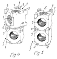
- FIGS. 3 to 5 and in particular with the help of Fig. 4 clearly recognizable where the first somewhat twisted position of the two parts to be coupled is shown.
- a connection part 2 with a flange 6 with a corresponding one of projections 8 and Undercuts 7 quick coupling formed by a Rotation coupled around 45 degrees, so connected very quickly become.
- holes 9 are indicated, which are each on a projection 8 and in the area project from its undercut 7. Take these holes 9 Clamping or grub screws on after performing the mutual connection can be turned to the through Lock quick coupling and counter coupling formed connection. So a slight screwing movement is enough to to improve the security of the mutual connection.
- outlet openings 5 there are three outlet openings 5 each with a quick coupling, i.e. with corresponding projections 8 in the corner areas.
- individual protrusions 8 designed so that over two at an angle to each other project standing side faces and undercuts there have if namely corresponding at an angle to each other standing surfaces each have an outlet opening 5.
- distributor housings 1 can also be connected to one another, i.e. a distributor housing 1 also a connection part of a further distributor housing 1 can form, as is also in FIGS. 3 to 6 and in FIG. 1 is shown.
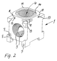
- the coupling projections 11 that match the quick coupling are protruding from the side surface Ring 13 arranged and are radially opposite this outside, which can be seen particularly clearly in FIG. 2.
- this coupling projections 11 in turn a shape that corresponds approximately to a flange 6 of a connecting part 2.
- all outlet openings 5 and Inlet opening 4 the same diameter. Furthermore, they all have a matching internal thread, so that connecting parts 3 can be attached, which have an external thread are, such as those marked as connector 3 in Fig. 1 Cable gland.
- the blind closure 10 is screwed into a corresponding internal thread. Practically there is thus a result at the inlet and outlet openings further coupling possibility, through which the versatility of the Distributor housing 1 or of several distributor housings and Connection parts existing kit is enlarged.
- a distributor housing 1 with Connection parts 2 and 3 can be, with the help of a quick coupling and a corresponding Counter coupling modular in almost any shape and mutual orientation can be put together to make different to be able to attach electrical connections.
- the mutual connection of the individual parts can be medium Quick coupling take place, so that a time-consuming attachment of several fastening screws on corresponding ones Flanges is avoided.
Landscapes
- Engineering & Computer Science (AREA)
- Architecture (AREA)
- Civil Engineering (AREA)
- Structural Engineering (AREA)
- Connector Housings Or Holding Contact Members (AREA)
- Connection Or Junction Boxes (AREA)
- Details Of Television Systems (AREA)
- Coupling Device And Connection With Printed Circuit (AREA)
Abstract
Description
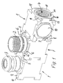
- Fig. 1
- mehrere miteinander mittels Schnellkupplung verbundene Verteilergehäuse mit Abschlußteilen,
- Fig. 2
- ein einzelnes Verteilergehäuse mit einer Eintrittsöffnung und mehreren Austrittsöffnungen mit einer Gegenkupplung für ein Anschlußteil, wobei im Bereich der Eintrittsöffnung eine zu diesen Gegenkupplungen passende Schnellkupplung angeordnet ist,
- Fig. 3
- zwei Verteilergehäuse vor ihrer gegenseitigen Befestigung mit Hilfe der Schnellkupplung einer Eintrittsöffnung, die zu der Gegenkupplung einer Austrittsöffnung paßt,
- Fig. 4
- einen ersten Montageschritt, bei welchem die eine Eintrittsöffnung aufweisende Fläche des einen Verteilergehäuses auf eine Austrittsöffnung aufweisende Fläche eines weiteren Verteilergehäuses aufgesetzt ist, wobei die Vorsprünge der Gegenkupplung zwischen den mit Hinterschneidungen versehenen Vorsprüngen der Schnellkupplung zu liegen kommen,
- Fig. 5
- die gegenseitige Verbindung der beiden Verteilergehäuse gemäß Fig. 4 nach einer gegenseitigen Verdrehung der beiden Verteilergehäuse um etwa 45 Grad,
- Fig. 6
- eine der Fig. 5 entsprechende Darstellung, bei welcher in gleicher Weise ein weiteres Verteilergehäuse zur Vorbereitung der Anordnung nach Fig. 1 angeschlossen ist.
Claims (15)
- Verteilergehäuse (1) mit Anschlußteilen (2,3) für elektrische Anschlüsse, wobei das Verteilergehäuse (1) wenigstens eine Eintrittsöffnung (4) für ein elektrisches Kabel und mindestens zwei Austrittsöffnungen (5) für von dem Kabel abgezweigte elektrische Anschlüsse aufweist und etwa quaderförmig ausgebildet ist, wobei die Eintrittsöffnung (4) sowie die Austrittsöffnungen (5) jeweils an einer Fläche dieses Quaders angeordnet sind und im Bereich der Austrittsöffnungen (5) zum Befestigen von die abgehenden elektrischen Anschlüsse enthaltenden Anschlußteilen (2) Verbindungsmittel für deren Montage vorgesehen sind, dadurch gekennzeichnet, daß zumindest im Bereich der Austrittsöffnungen an dem Verteilergehäuse (1) jeweils eine Schnellkupplung vorgesehen ist, zu der eine an dem Anschlußteil (2) angeordnete Gegenkupplung paßt.
- Verteilergehäuse nach Anspruch 1, dadurch gekennzeichnet, daß die Gegenkupplung an dem Anschlußteil (2) ein im wesentlichen vieleckiger oder viereckiger Flansch (6) ist, dessen Ecken abgeschrägt oder abgerundet sind, und daß die Schnellkupplung an dem Verteilergehäuse (1) durch den Flansch (6) in Gebrauchsstellung im Eckbereich übergreifende, mit Hinterschneidungen (7) ausgestattete Vorsprünge (8) gebildet ist, welche über die die zugehörige Eintritts- und/oder Austrittsöffnung aufweisende Seitenfläche des Verteilergehäuses (1) überstehen, wobei eine Begrenzung der Hinterschneidungen (7) jeweils etwa in der Ebene der Seitenfläche angeordnet oder von dieser gebildet ist, und daß die Vorsprünge (8) mit den Hinterschneidungen (7) einen derartigen Abstand zueinander haben, daß die Ecken der Flansche (6) vor dem Verdrehen dieser Flansche unter die Hinterschneidungen (7) zwischen benachbarte Vorsprünge (8) passen, so daß die Ecken der Flansche (6) von der Seite in die Hinterschneidungen (7) eindrehbar sind.
- Verteilergehäuse nach Anspruch 1 oder 2, dadurch gekennzeichnet, daß an wenigstens einem Vorsprung (8) im Bereich seiner Hinterschneidung (7) ein Klemmelement, insbesondere eine Klemmschraube oder Madenschraube vorgesehen ist.
- Verteilergehäuse nach einem der Ansprüche 1 bis 3, dadurch gekennzeichnet, daß drei Austrittsöffnungen (5) jeweils mit einer Schnellkupplung vorgesehen sind.
- Verteilergehäuse nach einem der Ansprüche 1 bis 4, dadurch gekennzeichnet, daß eine der Austrittsöffnungen (5) mit der Eintrittsöffnung (4) und die beiden anderen Austrittsöffnungen (5) miteinander fluchten.
- Verteilergehäuse nach einem der Ansprüche 1 bis 5, dadurch gekennzeichnet, daß das Verteilergehäuse (1) etwa die Form eines Würfels hat und an vier, fünf oder allen sechs Seitenflächen Öffnungen vorgesehen sind, die als Eintrittsund/oder Austrittsöffnungen ausgestaltet und mit Schnellkupplungen versehen sind.
- Verteilergehäuse nach einem der Ansprüche 1 bis 6, dadurch gekennzeichnet, daß an seiner eine Eintrittsöffnung (4) aufweisenden Fläche eine zu den Schnellkupplungen der Austrittsöffnungen (5) passende Gegenkupplung angeordnet und das Verteilergehäuse (1) mit dem Bereich seiner Eintrittsöffnung (4) mit einem weiteren Verteilergehäuse (1) im Bereich von einer von dessen Austrittsöffnungen (5) kuppelbar ist, so daß mehrere derartige übereinstimmende Verteilergehäuse (1) modular kombinierbar sind.
- Verteilergehäuse nach einem der Ansprüche 1 bis 7, dadurch gekennzeichnet, daß an mehreren seiner Flächen im Bereich mehrerer Eintrittsöffnungen (4) jeweils Gegenkupplungen angeordnet sind.
- Verteilergehäuse nach einem der Ansprüche 1 bis 8, dadurch gekennzeichnet, daß die im Bereich von Eintrittsöffnungen (4) angeordnete Gegenkupplung zu der Schnellkupplung und den dort vorgesehenen Hinterschneidungen (7) passende Kupplungsvorsprünge (11) aufweist, die gegenüber der die Eintrittsöffnung (4) aufweisenden Seitenfläche des Verteilergehäuses (1) einen Abstand haben, der etwa dem Abstand zwischen einer Hinterschneidung (7) und der Stirnseite (12) des zugehörigen Vorsprungs (8) entspricht.
- Verteilergehäuse nach einem der Ansprüche 1 bis 9, dadurch gekennzeichnet, daß die zu der Schnellkupplung passenden Kupplungsvorsprünge (11) an einem gegenüber der Seitenfläche vorspringenden Ring (13) angeordnet und diesem gegenüber radial vorstehen.
- Verteilergehäuse nach einem der Ansprüche 1 bis 10, dadurch gekennzeichnet, daß die an dem Ring (13) angeordneten Kupplungsvorsprünge (11) über einen Umfangsbereich verlaufen, der gleich oder kürzer als der Abstand zwischen zwei benachbarten, Hinterschneidungen (7) aufweisenden Vorsprüngen (8) der Schnellkupplung ist.
- Verteilergehäuse nach einem der Ansprüche 1 bis 11, dadurch gekennzeichnet, daß alle Austrittsöffnungen (5) oder alle Austrittsöffnungen (5) und die Eintrittsöffnungen (4) an dem Verteilergehäuse denselben Durchmesser haben.
- Verteilergehäuse nach einem der Ansprüche 1 bis 12, dadurch gekennzeichnet, daß die Eintritts- und/oder Austrittsöffnungen ein Innengewinde haben.
- Verteilergehäuse nach einem der Ansprüche 1 bis 13, dadurch gekennzeichnet, daß an dem als Gegenkupplung mit radial abstehenden Kupplungsvorsprüngen (11) ausgebildeten Ring (13) stirnseitig wenigstens eine Nut (14) zur Aufnahme eines Dichtringes angeordnet ist.
- Verteilergehäuse nach einem der vorstehenden Ansprüche, dadurch gekennzeichnet, daß die radial zur Mitte offenen Hinterschneidungen (7) in Umfangsrichtung an ihren beiden Enden offen sind.
Applications Claiming Priority (2)
| Application Number | Priority Date | Filing Date | Title |
|---|---|---|---|
| DE20106236U DE20106236U1 (de) | 2001-04-10 | 2001-04-10 | Verteilergehäuse mit Anschlußteilen |
| DE20106236U | 2001-04-10 |
Publications (3)
| Publication Number | Publication Date |
|---|---|
| EP1249913A2 true EP1249913A2 (de) | 2002-10-16 |
| EP1249913A3 EP1249913A3 (de) | 2003-10-01 |
| EP1249913B1 EP1249913B1 (de) | 2006-01-25 |
Family
ID=7955564
Family Applications (1)
| Application Number | Title | Priority Date | Filing Date |
|---|---|---|---|
| EP02003788A Expired - Lifetime EP1249913B1 (de) | 2001-04-10 | 2002-02-20 | Verteilergehäuse mit Anschlussteilen |
Country Status (4)
| Country | Link |
|---|---|
| EP (1) | EP1249913B1 (de) |
| AT (1) | ATE316703T1 (de) |
| DE (2) | DE20106236U1 (de) |
| ES (1) | ES2254542T3 (de) |
Cited By (4)
| Publication number | Priority date | Publication date | Assignee | Title |
|---|---|---|---|---|
| EP1432092A1 (de) * | 2002-12-16 | 2004-06-23 | Kastom S.r.l. | Elektrische Kabeldose |
| IT201900002551A1 (it) | 2019-02-21 | 2020-08-21 | Prysmian Spa | Scatola modulare di distribuzione per cavi |
| CN112121371A (zh) * | 2020-09-21 | 2020-12-25 | 巢湖学院 | 一种学前教育用体育锻炼装置 |
| US11784476B2 (en) | 2021-10-25 | 2023-10-10 | Bloomsburg Carpet Industries, Inc. | Modular junction box |
Families Citing this family (5)
| Publication number | Priority date | Publication date | Assignee | Title |
|---|---|---|---|---|
| DE20209059U1 (de) * | 2002-06-11 | 2003-10-16 | Weidmüller Interface GmbH & Co., 32760 Detmold | Anschlußvorrichtung, insbesondere Verteiler, mit einer Mehrzahl von Anschlußbuchsen und/oder -steckern |
| DE102004048770B4 (de) | 2004-10-05 | 2007-11-29 | Phoenix Contact Gmbh & Co. Kg | Gehäuseanordnung mit mindestens zwei Verbindungsdosen |
| DE102012104138B3 (de) * | 2012-03-23 | 2013-02-28 | Fpe Fischer Gmbh | Anschlusssystem für Solargeneratoren |
| CN110247348B (zh) * | 2019-06-19 | 2020-08-11 | 合肥流明新能源科技有限公司 | 一种多安装方式的组合拆分式接线设备 |
| EP4428371A1 (de) * | 2023-03-10 | 2024-09-11 | Wilo Se | Anordnung mit einem gehäuse für eine elektronische schaltung mit veränderbarer kabelverschraubungspositionierung |
Family Cites Families (5)
| Publication number | Priority date | Publication date | Assignee | Title |
|---|---|---|---|---|
| DE8912391U1 (de) | 1989-09-14 | 1991-01-24 | Kips, Ricus Cornelius Lawrence | Unterputzdose |
| DE4004340A1 (de) | 1990-02-13 | 1991-08-22 | Loh Kg Ritto Werk | Modulgehaeuse |
| DE9312476U1 (de) * | 1993-08-20 | 1993-10-21 | Wiska Hoppmann & Mulsow Gmbh, 24568 Kaltenkirchen | Kabeldose |
| DE4403238C1 (de) | 1994-02-03 | 1995-07-06 | Kaiser Gmbh & Co Kg | Variables Installationssystem - insbesondere für Leuchten - zum Einbau in Decken und/oder Wände |
| DE9412643U1 (de) | 1994-08-05 | 1994-12-08 | Kempf Widerstandsschweißtechnik GmbH, 63303 Dreieich | Elektroanschlußkasten |
-
2001
- 2001-04-10 DE DE20106236U patent/DE20106236U1/de not_active Expired - Lifetime
-
2002
- 2002-02-20 EP EP02003788A patent/EP1249913B1/de not_active Expired - Lifetime
- 2002-02-20 DE DE50205678T patent/DE50205678D1/de not_active Expired - Fee Related
- 2002-02-20 AT AT02003788T patent/ATE316703T1/de not_active IP Right Cessation
- 2002-02-20 ES ES02003788T patent/ES2254542T3/es not_active Expired - Lifetime
Cited By (7)
| Publication number | Priority date | Publication date | Assignee | Title |
|---|---|---|---|---|
| EP1432092A1 (de) * | 2002-12-16 | 2004-06-23 | Kastom S.r.l. | Elektrische Kabeldose |
| WO2004055953A1 (en) * | 2002-12-16 | 2004-07-01 | Kastom S.R.L. | Terminal for electrical cables |
| IT201900002551A1 (it) | 2019-02-21 | 2020-08-21 | Prysmian Spa | Scatola modulare di distribuzione per cavi |
| EP3700035A1 (de) | 2019-02-21 | 2020-08-26 | Prysmian S.p.A. | Modularer verteilerkasten für kabel |
| US11189996B2 (en) | 2019-02-21 | 2021-11-30 | Prysmian S.P.A. | Modular distribution box for cables |
| CN112121371A (zh) * | 2020-09-21 | 2020-12-25 | 巢湖学院 | 一种学前教育用体育锻炼装置 |
| US11784476B2 (en) | 2021-10-25 | 2023-10-10 | Bloomsburg Carpet Industries, Inc. | Modular junction box |
Also Published As
| Publication number | Publication date |
|---|---|
| DE20106236U1 (de) | 2001-06-21 |
| EP1249913A3 (de) | 2003-10-01 |
| ATE316703T1 (de) | 2006-02-15 |
| DE50205678D1 (de) | 2006-04-13 |
| EP1249913B1 (de) | 2006-01-25 |
| ES2254542T3 (es) | 2006-06-16 |
Similar Documents
| Publication | Publication Date | Title |
|---|---|---|
| EP3345258B1 (de) | In verschiedenen winkelstellungen fixierbarer halterahmen für steckverbindermodule | |
| EP1430245B1 (de) | Klemmverschraubung mit einer schraubhülse, einer gegenhülse und einem klemmeinsatz | |
| DE69408941T2 (de) | Gemischter elektrofluidischer Verbinder | |
| EP2545623B1 (de) | Kabelverschraubung mit klemmeinrichtung für eine armierung des kabels | |
| DE7126050U (de) | Flussigkeitsdichter spannungsfreier Verbinder | |
| DE2439527A1 (de) | Verbinder bzw. anschluss fuer rohre | |
| DE112014004206T5 (de) | Befestigungsvorrichtung für explosionssichere Gehäuse | |
| EP2240987B1 (de) | Steckvorrichtung | |
| DE1905625A1 (de) | Verbindungsglied zur Herstellung von Flachwerken | |
| EP0379496A1 (de) | Rohrverbindung zur bildung eines knotenpunktes. | |
| EP3625860A1 (de) | Kabeldurchführung | |
| EP2054977A1 (de) | Steckverbinder für vorderwandmontage oder hinterwandmontage | |
| EP2002130A1 (de) | Schnellverschluss | |
| DE202017107404U1 (de) | Knotenverbinder für Profilsysteme oder dergleichen | |
| EP1249913B1 (de) | Verteilergehäuse mit Anschlussteilen | |
| EP0125498B1 (de) | Steckeranordnung | |
| DE60206044T2 (de) | Speissschutzmuffe | |
| DE9406382U1 (de) | Winkel-Kabelverschraubung | |
| DE4441274C1 (de) | Sicherung für Steckverbindung | |
| DE102008060843B3 (de) | Umlenkvorrichtung für Kabel | |
| DE4116080C2 (de) | Lösbare Schnappverbindungsvorrichtung für zwei Bauelemente | |
| DE741309C (de) | Verbindung von Gehaeusen fuer die elektrische Installation miteinander und/oder mit Anbau- oder Zubehoerteilen | |
| DE10316270B3 (de) | Mehrteilige Abdeckung für Elektroinstallationseinsätze | |
| DE102012001968A1 (de) | Fluiddurchströmbare Baugruppe | |
| DE3439195C2 (de) |
Legal Events
| Date | Code | Title | Description |
|---|---|---|---|
| PUAI | Public reference made under article 153(3) epc to a published international application that has entered the european phase |
Free format text: ORIGINAL CODE: 0009012 |
|
| AK | Designated contracting states |
Kind code of ref document: A2 Designated state(s): AT BE CH CY DE DK ES FI FR GB GR IE IT LI LU MC NL PT SE TR |
|
| AX | Request for extension of the european patent |
Free format text: AL;LT;LV;MK;RO;SI |
|
| PUAL | Search report despatched |
Free format text: ORIGINAL CODE: 0009013 |
|
| AK | Designated contracting states |
Kind code of ref document: A3 Designated state(s): AT BE CH CY DE DK ES FI FR GB GR IE IT LI LU MC NL PT SE TR |
|
| AX | Request for extension of the european patent |
Extension state: AL LT LV MK RO SI |
|
| 17P | Request for examination filed |
Effective date: 20030917 |
|
| AKX | Designation fees paid |
Designated state(s): AT BE CH CY DE DK ES FI FR GB GR IE IT LI LU MC NL PT SE TR |
|
| 17Q | First examination report despatched |
Effective date: 20050425 |
|
| GRAP | Despatch of communication of intention to grant a patent |
Free format text: ORIGINAL CODE: EPIDOSNIGR1 |
|
| GRAS | Grant fee paid |
Free format text: ORIGINAL CODE: EPIDOSNIGR3 |
|
| GRAA | (expected) grant |
Free format text: ORIGINAL CODE: 0009210 |
|
| AK | Designated contracting states |
Kind code of ref document: B1 Designated state(s): AT BE CH CY DE DK ES FI FR GB GR IE IT LI LU MC NL PT SE TR |
|
| PG25 | Lapsed in a contracting state [announced via postgrant information from national office to epo] |
Ref country code: FI Free format text: LAPSE BECAUSE OF FAILURE TO SUBMIT A TRANSLATION OF THE DESCRIPTION OR TO PAY THE FEE WITHIN THE PRESCRIBED TIME-LIMIT Effective date: 20060125 Ref country code: NL Free format text: LAPSE BECAUSE OF FAILURE TO SUBMIT A TRANSLATION OF THE DESCRIPTION OR TO PAY THE FEE WITHIN THE PRESCRIBED TIME-LIMIT Effective date: 20060125 Ref country code: IE Free format text: LAPSE BECAUSE OF FAILURE TO SUBMIT A TRANSLATION OF THE DESCRIPTION OR TO PAY THE FEE WITHIN THE PRESCRIBED TIME-LIMIT Effective date: 20060125 |
|
| REG | Reference to a national code |
Ref country code: GB Ref legal event code: FG4D Free format text: NOT ENGLISH |
|
| REG | Reference to a national code |
Ref country code: CH Ref legal event code: EP |
|
| PG25 | Lapsed in a contracting state [announced via postgrant information from national office to epo] |
Ref country code: AT Free format text: LAPSE BECAUSE OF NON-PAYMENT OF DUE FEES Effective date: 20060220 |
|
| REG | Reference to a national code |
Ref country code: IE Ref legal event code: FG4D Free format text: LANGUAGE OF EP DOCUMENT: GERMAN |
|
| PG25 | Lapsed in a contracting state [announced via postgrant information from national office to epo] |
Ref country code: MC Free format text: LAPSE BECAUSE OF NON-PAYMENT OF DUE FEES Effective date: 20060228 Ref country code: BE Free format text: LAPSE BECAUSE OF NON-PAYMENT OF DUE FEES Effective date: 20060228 |
|
| REG | Reference to a national code |
Ref country code: CH Ref legal event code: NV Representative=s name: HANS RUDOLF GACHNANG PATENTANWALT |
|
| REG | Reference to a national code |
Ref country code: SE Ref legal event code: TRGR |
|
| PG25 | Lapsed in a contracting state [announced via postgrant information from national office to epo] |
Ref country code: LU Free format text: LAPSE BECAUSE OF NON-PAYMENT OF DUE FEES Effective date: 20060325 |
|
| REF | Corresponds to: |
Ref document number: 50205678 Country of ref document: DE Date of ref document: 20060413 Kind code of ref document: P |
|
| PG25 | Lapsed in a contracting state [announced via postgrant information from national office to epo] |
Ref country code: DK Free format text: LAPSE BECAUSE OF FAILURE TO SUBMIT A TRANSLATION OF THE DESCRIPTION OR TO PAY THE FEE WITHIN THE PRESCRIBED TIME-LIMIT Effective date: 20060425 |
|
| GBT | Gb: translation of ep patent filed (gb section 77(6)(a)/1977) |
Effective date: 20060508 |
|
| REG | Reference to a national code |
Ref country code: ES Ref legal event code: FG2A Ref document number: 2254542 Country of ref document: ES Kind code of ref document: T3 |
|
| PG25 | Lapsed in a contracting state [announced via postgrant information from national office to epo] |
Ref country code: PT Free format text: LAPSE BECAUSE OF FAILURE TO SUBMIT A TRANSLATION OF THE DESCRIPTION OR TO PAY THE FEE WITHIN THE PRESCRIBED TIME-LIMIT Effective date: 20060626 |
|
| NLV1 | Nl: lapsed or annulled due to failure to fulfill the requirements of art. 29p and 29m of the patents act | ||
| ET | Fr: translation filed | ||
| REG | Reference to a national code |
Ref country code: IE Ref legal event code: FD4D |
|
| PLBE | No opposition filed within time limit |
Free format text: ORIGINAL CODE: 0009261 |
|
| STAA | Information on the status of an ep patent application or granted ep patent |
Free format text: STATUS: NO OPPOSITION FILED WITHIN TIME LIMIT |
|
| 26N | No opposition filed |
Effective date: 20061026 |
|
| BERE | Be: lapsed |
Owner name: ANTON HUMMEL VERWALTUNGS G.M.B.H. Effective date: 20060228 |
|
| PG25 | Lapsed in a contracting state [announced via postgrant information from national office to epo] |
Ref country code: GR Free format text: LAPSE BECAUSE OF FAILURE TO SUBMIT A TRANSLATION OF THE DESCRIPTION OR TO PAY THE FEE WITHIN THE PRESCRIBED TIME-LIMIT Effective date: 20060426 |
|
| PGFP | Annual fee paid to national office [announced via postgrant information from national office to epo] |
Ref country code: CH Payment date: 20080215 Year of fee payment: 7 Ref country code: ES Payment date: 20080124 Year of fee payment: 7 |
|
| PGFP | Annual fee paid to national office [announced via postgrant information from national office to epo] |
Ref country code: DE Payment date: 20080204 Year of fee payment: 7 Ref country code: GB Payment date: 20080206 Year of fee payment: 7 Ref country code: IT Payment date: 20080227 Year of fee payment: 7 Ref country code: SE Payment date: 20080213 Year of fee payment: 7 |
|
| PG25 | Lapsed in a contracting state [announced via postgrant information from national office to epo] |
Ref country code: TR Free format text: LAPSE BECAUSE OF FAILURE TO SUBMIT A TRANSLATION OF THE DESCRIPTION OR TO PAY THE FEE WITHIN THE PRESCRIBED TIME-LIMIT Effective date: 20060125 |
|
| PGFP | Annual fee paid to national office [announced via postgrant information from national office to epo] |
Ref country code: FR Payment date: 20080117 Year of fee payment: 7 |
|
| PG25 | Lapsed in a contracting state [announced via postgrant information from national office to epo] |
Ref country code: CY Free format text: LAPSE BECAUSE OF FAILURE TO SUBMIT A TRANSLATION OF THE DESCRIPTION OR TO PAY THE FEE WITHIN THE PRESCRIBED TIME-LIMIT Effective date: 20060125 |
|
| REG | Reference to a national code |
Ref country code: CH Ref legal event code: PL |
|
| EUG | Se: european patent has lapsed | ||
| GBPC | Gb: european patent ceased through non-payment of renewal fee |
Effective date: 20090220 |
|
| PG25 | Lapsed in a contracting state [announced via postgrant information from national office to epo] |
Ref country code: LI Free format text: LAPSE BECAUSE OF NON-PAYMENT OF DUE FEES Effective date: 20090228 Ref country code: CH Free format text: LAPSE BECAUSE OF NON-PAYMENT OF DUE FEES Effective date: 20090228 |
|
| REG | Reference to a national code |
Ref country code: FR Ref legal event code: ST Effective date: 20091030 |
|
| PG25 | Lapsed in a contracting state [announced via postgrant information from national office to epo] |
Ref country code: DE Free format text: LAPSE BECAUSE OF NON-PAYMENT OF DUE FEES Effective date: 20090901 |
|
| REG | Reference to a national code |
Ref country code: ES Ref legal event code: FD2A Effective date: 20090221 |
|
| PG25 | Lapsed in a contracting state [announced via postgrant information from national office to epo] |
Ref country code: GB Free format text: LAPSE BECAUSE OF NON-PAYMENT OF DUE FEES Effective date: 20090220 Ref country code: FR Free format text: LAPSE BECAUSE OF NON-PAYMENT OF DUE FEES Effective date: 20090302 |
|
| PG25 | Lapsed in a contracting state [announced via postgrant information from national office to epo] |
Ref country code: ES Free format text: LAPSE BECAUSE OF NON-PAYMENT OF DUE FEES Effective date: 20090221 |
|
| PG25 | Lapsed in a contracting state [announced via postgrant information from national office to epo] |
Ref country code: IT Free format text: LAPSE BECAUSE OF NON-PAYMENT OF DUE FEES Effective date: 20090220 |
|
| PG25 | Lapsed in a contracting state [announced via postgrant information from national office to epo] |
Ref country code: SE Free format text: LAPSE BECAUSE OF NON-PAYMENT OF DUE FEES Effective date: 20090221 |