EP1248499B1 - Verfahren und Vorrichtung zum Erzeugen von extrem ultravioletter Strahlung - Google Patents
Verfahren und Vorrichtung zum Erzeugen von extrem ultravioletter Strahlung Download PDFInfo
- Publication number
- EP1248499B1 EP1248499B1 EP01125762A EP01125762A EP1248499B1 EP 1248499 B1 EP1248499 B1 EP 1248499B1 EP 01125762 A EP01125762 A EP 01125762A EP 01125762 A EP01125762 A EP 01125762A EP 1248499 B1 EP1248499 B1 EP 1248499B1
- Authority
- EP
- European Patent Office
- Prior art keywords
- electrode
- trigger
- electrodes
- trigger electrode
- plasma
- Prior art date
- Legal status (The legal status is an assumption and is not a legal conclusion. Google has not performed a legal analysis and makes no representation as to the accuracy of the status listed.)
- Expired - Lifetime
Links
Images


Classifications
-
- H—ELECTRICITY
- H05—ELECTRIC TECHNIQUES NOT OTHERWISE PROVIDED FOR
- H05G—X-RAY TECHNIQUE
- H05G2/00—Apparatus or processes specially adapted for producing X-rays, not involving X-ray tubes, e.g. involving generation of a plasma
- H05G2/001—Production of X-ray radiation generated from plasma
- H05G2/003—Production of X-ray radiation generated from plasma the plasma being generated from a material in a liquid or gas state
-
- G—PHYSICS
- G03—PHOTOGRAPHY; CINEMATOGRAPHY; ANALOGOUS TECHNIQUES USING WAVES OTHER THAN OPTICAL WAVES; ELECTROGRAPHY; HOLOGRAPHY
- G03F—PHOTOMECHANICAL PRODUCTION OF TEXTURED OR PATTERNED SURFACES, e.g. FOR PRINTING, FOR PROCESSING OF SEMICONDUCTOR DEVICES; MATERIALS THEREFOR; ORIGINALS THEREFOR; APPARATUS SPECIALLY ADAPTED THEREFOR
- G03F7/00—Photomechanical, e.g. photolithographic, production of textured or patterned surfaces, e.g. printing surfaces; Materials therefor, e.g. comprising photoresists; Apparatus specially adapted therefor
- G03F7/70—Microphotolithographic exposure; Apparatus therefor
- G03F7/70008—Production of exposure light, i.e. light sources
- G03F7/70033—Production of exposure light, i.e. light sources by plasma extreme ultraviolet [EUV] sources
Definitions
- the invention relates to a method having the features of the preamble of claim 1.
- a method with the preceding method steps is known from DE-A-197 53 696 known.
- the method is performed with a device having a discharge space forming electrode system.
- This electrode system generates extremely ultraviolet radiation and soft X-rays, which are used in particular for EUV lithography.
- the electrode system consists of two electrodes, namely a cathode and an anode, each of which is formed with an opening.
- the opening is essentially a hole and both openings lie on a common axis of symmetry.
- the cathode is formed as a hollow cathode, thus has a cavity. This is used to form the electric field in a predetermined manner.
- the arrangement of the electrodes is such that the field lines in the area of the boreholes are sufficiently stretched so that the breakdown condition above a certain voltage is met.
- the discharge space is filled with gas and the gas pressure is at least in the range of the electrode system in the order of 1 Pa to 100 Pa.
- the geometry of the electrodes and the gas pressure are chosen that the desired ignition of the plasma takes place on the left branch of the Paschen curve and as a result no dielectric breakdown occurs between the electrodes outside the openings.
- a current-carrying plasma channel of axially symmetrical shape is formed, namely in the region of the openings of the electrodes. With the help of the energy storage, a current is sent over this channel.
- the resulting Lorentz force laced the plasma. Due to this constriction effect and ohmic heating, very high temperatures occur in the plasma and very short wavelength radiation is generated.
- the known device can generate EUV light in the wavelength range of 10-20 nm.
- the method is essential that can basically be dispensed with a switching element between the electrode system and the energy storage. Therefore, a low-inductive and effective coupling of the electrically stored energy into the electrode system can be achieved. Pulse energies of a few joules are sufficient to cause current pulses in the range of several kilo-amperes up to several 10 kilo-amps. A triggering of the energy coupling in the controlled or self-breakdown discharge takes place in coordination with a predetermined ignition voltage.
- the ignition voltage is influenced, for example, by the gas composition, the temperature, a pre-ionization, the electric field distribution and other variables. It can be adjusted according to the Paschen curve by means of the gas pressure of the discharge vessel.
- breakthroughs repeat in rapid succession to produce continuous radiation. Between two breakthroughs, the system requires a certain time for recombination of the gas in the discharge space. During this time, the gas at least partially returns to its initial state, so that the energy store can be reloaded and the required voltage can be built up at its electrodes. As a result, the state of the system also depends on when the last breakthrough took place or at what repetition frequency the generation of the radiation took place. At high repetition frequency, the working point on the Paschen curve will be different than at low repetition frequency. In practice this means that the repetition frequency can be very limited because no stable operating point can be found at all.
- the invention has for its object to improve a method with the above-mentioned method steps so that when operated in pulse mode method for generating the EUV light precise control of the pulses can be achieved, especially in a wide parameter field of the discharge processes.
- the triggering influences the ignition conditions for the plasma.
- the triggering affects the distribution of charge carriers in the ignition region of the plasma and thus also the point in time at which the ignition takes place effectively.
- the potential of the trigger electrode is higher before the triggering process, than that of the cathode.
- the method is performed so that a voltage of the trigger electrode relative to the electrode used as a cathode, the voltage across the two electrodes and the gas pressure of the discharge space are set so that upon application of the trigger voltage, an ignition of the plasma does not occur, the first is initiated by switching off the trigger voltage.
- the switching off of the trigger voltage enables such an electric field formation in the discharge space that the breakdown conditions are met.
- the time of the breakthrough can be precisely determined by the trigger signal, namely the switching off of the trigger voltage. It is also important that the parameter range for a discharge can be considerably extended.
- the pressure in the gas space, the distance between the electrodes and the voltage at the electrodes can be chosen differently depending on the trigger voltage. While the breakthrough in the ungroduced case is only determined by a single point on the Paschen curve, in the triggered case large voltage ranges ⁇ U or pressure ranges ⁇ P can be defined, in which there is a breakthrough after the trigger pulse.
- an operating interval starts with the switch-on and ends with the switch-off.
- a service interval for example, a wafer is exposed in a partial area.
- the radiation required for the exposure is carried out according to one of the above-described methods, with a fixed repetition frequency.
- an adjustment of the exposure device and / or the waver can take place, in order to then carry out the process again after reexposing the same wafer or another wafer at a predetermined repetition frequency.
- the invention also relates to a device having the features of the preamble of claim 5.
- ionization may occur in the discharge space.
- the mobile ions in the electric field impinge on the trigger electrode and usually have a sufficiently large energy to beat secondary electrons from the metallic surface of the electrode. These electrons reach the anode because of the potential difference.
- a conductive channel may be formed between the anode and the trigger electrode without the desired breakthrough already occurring in the region of the openings of the electrodes.
- a significant part of the energy storage can be discharged via the trigger circuit, which brings the risk of destruction of this circle with it.
- a problem may arise in that the potential of the trigger electrode drops to the level of the anode due to the formation of a conductive channel, whereby a high voltage is formed with respect to the cathode. As a result, unwanted discharges between the cathode and the trigger electrode may occur, which also interfere with the proper functioning of the device.
- an ion or particle beam can cause it, because of its high energy atomizes at least parts of the cathode. This leads to undesirable wear and deposits of atomizing particles on the surrounding surfaces.
- the invention has the object, a device with the aforementioned features in such a way that a long life without interference of the function is achieved.
- the above object is solved by the features of the characterizing part of claim 5. If the carrier electrode is arranged outside of a particle beam which forms in the axis of symmetry, the particles or ions accelerated in this axis no longer hit the carrier electrode. The above-described malfunctions are therefore at least considerably reduced. The same applies if the trigger electrode has a shield which prevents a build-up of a conductive channel between the trigger electrode and the anode.
- An advantageous embodiment of the device is characterized in that the trigger electrode is arranged in the axis of symmetry of the openings of the electrodes and an end face facing the openings at least in the formation region of the particle beam an insulator as a shield having.
- the arrangement of the trigger electrode in the axis of symmetry can be made so that a uniform influence of the field lines in the discharge space can be achieved safely.
- the insulator provides the desired protection of the trigger electrode without significantly distorting the field lines in the discharge space.
- the insulator is designed as a layer applied to the end face of the trigger electrode.
- the trigger electrode is sufficiently protected in this case with minimal use of materials.
- the device can also be designed so that the insulator is formed as embedded in the end face of the trigger electrode body.
- the trigger electrode should be assembled with the insulator using the usual mechanical means of production.
- An advantageous embodiment of the device can be distinguished by the fact that the insulator has a depression with a cross-section matched to the particle beam. A particle beam can hit a bottom of the depression in this case. As a result, resulting sputtering products deposit mainly on the inner walls of the recess and therefore hardly disturb the other surfaces of the arrangement.
- the recess of the insulator When the recess of the insulator is conically tapered, the energy of an ion beam is distributed over a larger surface area and thus the local thermal heating is reduced. Correspondingly fewer sputtering products are formed.
- the device in such a way that the trigger electrode is completely insulated at least against the space adjoining the first electrode.
- the preparation of the trigger electrode for such a device can be influenced by a complete insulation or coating advantageous. Also, inhomogeneities in field or discharge formation on the metal surfaces of the trigger electrode are eliminated in the transition region between isolated and non-isolated metal surfaces.
- a disadvantage may be in a complete isolation of the trigger electrode that under certain discharge conditions accumulate electrical charges on the isolated surface, which could cause a shielding of the trigger potential.
- the device may be formed so that the shield of the trigger electrode has a residual conductivity capable of dissipating surface charges but preventing discharge-affecting current flow between the second electrode and the trigger electrode. Also in this case of shielding degrading surface discharges, it is advantageous to completely insulate the trigger electrode to avoid additional leakage paths.
- the trigger electrode is not to be in the axis of symmetry, it is preferable to form the device so that the trigger electrode is formed as a hollow cylinder surrounding the symmetry axis.
- the device may be formed such that a hollow cylindrical trigger electrode has a bottom facing away from the two electrodes, which is formed as an insulator or which is a metal bottom having the potential of one of the electrodes, for which it is isolated from the trigger electrode.
- the insulator can then take over the functions of the insulators described above, in particular with regard to a possible particle beam. If the bottom is a metal bottom, it can either be placed at the potential of the anode, so that a conductive channel does not arise because of potential equality.
- the metal floor can but be placed on the potential of the cathode to suck up resulting charge carriers.
- the trigger electrode is an annular disc or at least one electrode pin, which / is installed transversely to the axis of symmetry of the electrodes in the first electrode / are.
- the annular disk or with an electrode pin the electric field in the discharge space or in the adjoining the trigger electrode space can be influenced in order to influence the discharge behavior of the device.
- the trigger electrode is isolated in the first electrode.
- the device is exposed in their function considerable heat development. It is therefore expedient to design them so that the shield consists of temperature-resistant insulation material.
- the shield is connected to the trigger electrode thermally well conductive to dissipate heat.
- the device In order to absorb the majority of the charge carriers, which reach a shield in the region of the axis of symmetry, the device is expediently designed so that the shield has a diameter which corresponds at least to the diameter of the openings.
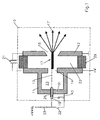
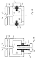
- Fig.1 schematically shows the formation of a arranged in a discharge space 10 electrode system.
- the discharge space 10 is filled with gas of predetermined gas pressure and may be formed by suitably formed electrodes of the electrode system itself.
- the gas pressure is adjustable.
- the equipment of the discharge vessel 10 required for adjusting the gas pressure and a configuration of the electrode system which is adapted thereto are present, but not shown.
- the electrode 12 is formed as an anode with a central opening 15 which widens conically starting from an electrode gap 22.
- the electrode 11 is formed as a cathode, as a hollow cathode with a cavity 23 which is connected via an opening 14 of the cathode to the electrode gap 22.
- the openings 14,15 are aligned and form an axis of symmetry 13 of the electrode system.
- the electrodes 11, 12 are insulated from one another. An insulator 29 serving for this purpose determines the electrode spacing.
- the electrode system is able to form field lines when an electrical high voltage in the range of, for example, a few 10 kV is applied, which in any case extend in the region of the electrode gap 22 rectilinearly and parallel to the axis of symmetry 13. If the voltage is increased in pulses starting from a predetermined low value, the result is a loading ramp or an increase in voltage. It comes to Ionisationsvorêtn that focus due to the field strength ratios in the electrode gap 22.
- the voltage rise and the gas pressure are coordinated so that it comes as a result of ionization to a gas discharge on the left branch of the Paschenkurve in which a plasma channel or its plasma is not built on a single short-term electron avalanche, but in several stages on Sekundärionisationsreae.
- the plasma distribution is already highly cylindrically symmetric in the starting phase, as the schematic representation of the plasma in the Fig.1 should express.
- the forming plasma 17 is a source of the radiation 17 'to be generated, an electron beam.
- the formed plasma may be referred to as start plasma. It can serve the energy input from an energy store in self-breakdown mode.
- Fig.1 shows a capacitor bank 21 as energy storage, which discharges after reaching the predetermined ignition voltage and thereby allows to feed current pulses in the two-digit kilo-ampere range in the plasma.
- the resulting Lorentz forces of the magnetic field constrict the plasma, resulting in a high luminance and in particular for the formation of extreme ultraviolet radiation and soft X-radiation, which has the required wavelengths, in particular for EUV lithography.
- FIG. 1 shown electrode system is provided in the region of the electrode 11 with a trigger device.
- the electrode 11 in the axis of symmetry 13, a trigger electrode 19, which is held by an insulator 26 in the bottom 30 of the electrode 11.
- the insulator 26 serves to allow the trigger electrode 19 to be given a potential different from that of the electrode 11.
- the trigger electrode 19 has a parasitic capacitance 31 with respect to the electrode 11, measured in parallel with a switch 32, with which both electrodes 19,11 can be brought to the same potential.
- the electrode 12 is formed as an anode and grounded as shown.
- the cathode is at a negative potential -V while the trigger electrode 19 is at a potential -V + V t .
- the potential of the trigger electrode before the start of the triggering process is therefore slightly higher than that of the electrode 11.
- a trigger pulse is triggered by closing the switch 32, wherein the potential of the trigger electrode 19 is pulled down to that of the electrode 11.
- Typical time constants for a change in the potential of the trigger electrode 19 are advantageously in the range of a few nanoseconds to a few hundred nanoseconds.
- FIG.1 schematically illustrated electrode assembly is typically formed so that between the electrodes 11,12 a distance of 1 to 10 mm is present.
- the smallest passage of the openings 14,15 is typically 1 to 10 mm.
- the volume of the space 23 in the hollow cathode formed electrode 11 is typically 1 to 10 cc.
- the gas pressure is between 0.01 and 1 mbar.
- the electrode voltage is typically 3 to 30 kV and the potential difference between the trigger electrode 19 and the electrode 11 is between 50 volts and 1000 volts.
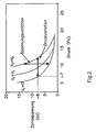
- the ignition voltage in which there is a breakdown between the electrodes 11,12, and the pressure corresponding to in Fig.2 shown curve interdependent.
- the Fig.2 refers to the left branch of the Paschen curve.
- the left curve of the Fig.2 applies to the operation of the ungetriggered device.
- V 0
- the trigger voltage that is, the potential difference between the trigger electrode 19 and the electrode 1
- V t is not equal to 0 but, for example, equal to V 1 or V 2 .
- V t can be achieved by suitable sizing of the trigger voltage V t , that the device can be operated with different parameters. For a predetermined voltage at the electrodes 11,12, the possibility arises to off Fig.2 apparent pressure variation.
- the off Fig.2 apparent voltage variation possible. Accordingly, however, the time of the breakthrough with the trigger signal can be set precisely without thereby entering a work area in which the difficulties described above occur.
- repetition frequencies can be ensured, as they are necessary for the required use, for example in the range of 10 to 20 kHz.
- Operating intervals for predetermined fixed repetition frequencies are also possible, as a result of which the energy required per se for generating the desired radiation can be saved between the operating intervals. The stability of the operating point is significantly improved.
- the triggering is done by the in Fig.1 achieved circuit shown.
- the capacitor bank 21 is charged by applying the electrode 11 to negative voltage while the electrode 12 is grounded.
- the connection of the two electrodes 11,12 via a low-inductance circuit with the capacitor bank 21.
- a high-impedance circuit connects the trigger electrode 19 to the electrode 11, wherein the connection can be opened by the switch 32.
- V t there is a potential difference V t at the trigger electrode 19 opposite to the electrode 11.
- the voltages at the electrodes 11,12 and the gas pressure of the Electrode gap or the space 23 of the electrode 11 is set so that upon application of a trigger voltage V t ignition of the plasma 17 can not take place. If the switch 32 is closed, however, the potential difference V t is eliminated and the trigger electrode 19 receives the potential of the electrode 11, wherein a protective resistor 33 protects the voltage source of the trigger voltage.
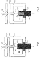
- 3 to 11 show trigger electrodes 19, which are arranged coaxially with the axis of symmetry 13, which is formed by the electrodes 11,12 and their openings 14,15.
- the trigger electrodes 19 are the 3 to 8 designed so that they face the opening 14 an end face 34. However, at least this end face 34 is in each case provided with a respectively differently designed shielding 35.
- Each shield 35 is at least as large as corresponds to the diameter of the openings 14,15. The shield 35 is thus present in the vicinity of the trigger electrode 19 in the formation region of the particle beam.
- the shield 35 is formed as an insulator in the form of a layer applied to the end face 34 of the trigger electrode 19 layer.
- the cross-section of this body is, for example, circular cylindrical, to be inserted in a conventional manner in a bore of the trigger electrode 19, which is introduced from the end face 34 ago.
- the trigger electrode 19 is the same as in FIG Figure 4 trained. In their bore, however, different shields 35 are used.
- the shield 35 of Figure 5 is again a cylindrical body, but which has an equiaxed depression 36 which is formed as a blind hole.
- the diameter of the blind bore is matched to the diameter of the potential particle beam.
- the shield 35 of Figure 6 is formed with a recess 36 which tapers conically away from the openings 14,15. An approximately forming particle beam strikes comparatively large areas of the shield 35, so that the beam energy is distributed over a larger surface, which prevents local thermal heating.
- the Fig.5,6 For example, the depressions are suitable for absorbing sputtering products which are formed as a result of a particle beam and which can deposit on the inner walls of the depressions 36 and therefore hardly disturb the other surfaces of the arrangement.
- the trigger electrodes of the Fig.7,8 are characterized by the fact that they are completely isolated from their shielding at least against the space 23 adjacent to the first electrode 11.
- the shield 35 is a coating that leaves free the surface of the trigger electrode 19 at any point. As a result, there can not be any inhomogeneities of the electric field that would be caused by such release. Under certain discharge conditions, however, it may happen that accumulate on the surface of this shield 35 electrical charges that can cause a shielding of the trigger voltage. Shielding the trigger voltage would cause the device to malfunction.
- Such shields can be prevented if the shield 35 with a residual conductivity is large enough to neutralize the built surface discharges or dismantle. However, this residual conductivity is not large enough to allow a current flow between the electrode 12 and the trigger electrode 19, which discharges the capacitor bank 21 significantly.
- Figure 8 shows such a shield 35 with a suitable residual conductivity.
- the dimensions can vary within wide limits.
- the trigger electrode 19 may for example be designed as a thin wire, which then expediently according to Fig.7,8 is coated.
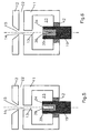
- the trigger electrodes 19 of the 9 to 11 are hollow cylindrical. These trigger electrodes are also arranged coaxially with the axis of symmetry 13. As a result of their hollow cylindrical design and the field formation, moreover, a particle beam forming in the region of the axis of symmetry 13 can not reach the trigger electrode 19 and have a disruptive or destructive effect there.
- the trigger electrode 19 is closed by a metallic bottom 37, which is at ground potential and insulated from the hollow cylindrical trigger electrode 19. Between the bottom 37 and the electrode 12, no particle beam can form, because this electrode is also at ground potential as an anode.
- FIG 11 is a bottom 38 formed as an insulator and thus has a similar effect with respect to the particle beam, as to the 3 to 6 described shields.
- the bottom 39 of the hollow cylindrical trigger electrode 19 is designed as a metal electrode, which is conductively connected to the electrode 11, the cathode.
- Charge carriers of particle beams present in the symmetry axis are supplied by means of the metallic bottom 39 via a connecting line 40 of the electrode 12.
- Figure 12 The embodiments of Figure 12 and 13 are alternative arrangements too Figure 11 , In all cases, charged particles located in the symmetry axis 13 or in the space 23 are fed to the electrode 11.
- the trigger electrode 19 is designed as an annular disc. This annular disk is installed transversely to the axis of symmetry 13 of the electrodes 11, 12 in the first electrode 11. Theirs in Figure 12 Upper and lower halves are conductively connected by a dashed line 41, so have the same potential.
- the arrangement of the trigger electrode 19 is cylindrically symmetric with respect to the axis of symmetry 13. That is in the case of Figure 13 no longer the case. In this embodiment may - except for the line 41 - be seen from the side configuration, as in Figure 12 was presented.
- the symmetry axis 13 is in Figure 13 however perpendicular to the plane of representation and Figure 13 shows two identically formed parts 19 'and 19''of a trigger electrode, which are arranged coaxially and transversely to the axis of symmetry 13.
- the parts 19 ', 19'' represent electrode pins.
- the trigger electrode can also have several parts.
- the shields 35 used in the trigger electrodes 19 are made of temperature-resistant insulating materials, such as Al 2 O 3 , quartz or silicon carbide. All materials used for shields 35 are thermally well connected to the trigger electrode 19.
- the trigger electrode 19 or its parts 19 ', 19'' is installed in the first electrode 11 isolated / are.
- the in the FIGS. 3 to 13 shown insulation 42 perform the same functions as the insulator 26 of Fig.1 , The relevant insulation 42 is temperature resistant.
Landscapes
- Physics & Mathematics (AREA)
- Engineering & Computer Science (AREA)
- Plasma & Fusion (AREA)
- Optics & Photonics (AREA)
- General Physics & Mathematics (AREA)
- Exposure And Positioning Against Photoresist Photosensitive Materials (AREA)
- X-Ray Techniques (AREA)
- Plasma Technology (AREA)
- Physical Or Chemical Processes And Apparatus (AREA)
Priority Applications (7)
| Application Number | Priority Date | Filing Date | Title |
|---|---|---|---|
| TW091104540A TWI284916B (en) | 2001-04-06 | 2002-03-12 | Method and device for producing extreme ultraviolet radiation and soft x-ray radiation |
| US10/474,121 US7126143B2 (en) | 2001-04-06 | 2002-03-23 | Method and device for producing extreme ultraviolet radiation and soft x-ray radiation |
| CNB02807825XA CN1311716C (zh) | 2001-04-06 | 2002-03-23 | 产生远紫外辐照和软x射线辐照的方法和装置 |
| JP2002580685A JP4330344B2 (ja) | 2001-04-06 | 2002-03-23 | 超紫外線及び軟x線の発生方法及び装置 |
| DE10291549T DE10291549D2 (de) | 2001-04-06 | 2002-03-23 | Verfahren und Vorrichtung zum Erzeugen von extrem ultravioletter Strahlung und weicher Röntgenstrahlung |
| EP02729817A EP1374650A1 (de) | 2001-04-06 | 2002-03-23 | Verfahren und vorrichtung zum erzeugen von extrem ultravioletter strahlung und weicher röntgenstrahlung |
| PCT/DE2002/001085 WO2002082872A1 (de) | 2001-04-06 | 2002-03-23 | Verfahren und vorrichtung zum erzeugen von extrem ultravioletter strahlung und weicher röntgenstrahlung |
Applications Claiming Priority (4)
| Application Number | Priority Date | Filing Date | Title |
|---|---|---|---|
| DE10117377 | 2001-04-06 | ||
| DE10117377 | 2001-04-06 | ||
| DE10139677 | 2001-08-11 | ||
| DE10139677A DE10139677A1 (de) | 2001-04-06 | 2001-08-11 | Verfahren und Vorrichtung zum Erzeugen von extrem ultravioletter Strahlung und weicher Röntgenstrahlung |
Publications (2)
| Publication Number | Publication Date |
|---|---|
| EP1248499A1 EP1248499A1 (de) | 2002-10-09 |
| EP1248499B1 true EP1248499B1 (de) | 2010-05-26 |
Family
ID=26009027
Family Applications (2)
| Application Number | Title | Priority Date | Filing Date |
|---|---|---|---|
| EP01125762A Expired - Lifetime EP1248499B1 (de) | 2001-04-06 | 2001-10-29 | Verfahren und Vorrichtung zum Erzeugen von extrem ultravioletter Strahlung |
| EP02729817A Withdrawn EP1374650A1 (de) | 2001-04-06 | 2002-03-23 | Verfahren und vorrichtung zum erzeugen von extrem ultravioletter strahlung und weicher röntgenstrahlung |
Family Applications After (1)
| Application Number | Title | Priority Date | Filing Date |
|---|---|---|---|
| EP02729817A Withdrawn EP1374650A1 (de) | 2001-04-06 | 2002-03-23 | Verfahren und vorrichtung zum erzeugen von extrem ultravioletter strahlung und weicher röntgenstrahlung |
Country Status (8)
| Country | Link |
|---|---|
| US (1) | US7126143B2 (cg-RX-API-DMAC7.html) |
| EP (2) | EP1248499B1 (cg-RX-API-DMAC7.html) |
| JP (1) | JP4330344B2 (cg-RX-API-DMAC7.html) |
| CN (1) | CN1311716C (cg-RX-API-DMAC7.html) |
| AT (1) | ATE469533T1 (cg-RX-API-DMAC7.html) |
| DE (3) | DE10139677A1 (cg-RX-API-DMAC7.html) |
| TW (1) | TWI284916B (cg-RX-API-DMAC7.html) |
| WO (1) | WO2002082872A1 (cg-RX-API-DMAC7.html) |
Families Citing this family (26)
| Publication number | Priority date | Publication date | Assignee | Title |
|---|---|---|---|---|
| DE10238096B3 (de) * | 2002-08-21 | 2004-02-19 | Fraunhofer-Gesellschaft zur Förderung der angewandten Forschung e.V. | Gasentladungslampe |
| US6770895B2 (en) | 2002-11-21 | 2004-08-03 | Asml Holding N.V. | Method and apparatus for isolating light source gas from main chamber gas in a lithography tool |
| DE10256663B3 (de) * | 2002-12-04 | 2005-10-13 | Fraunhofer-Gesellschaft zur Förderung der angewandten Forschung e.V. | Gasentladungslampe für EUV-Strahlung |
| DE10260458B3 (de) * | 2002-12-19 | 2004-07-22 | Xtreme Technologies Gmbh | Strahlungsquelle mit hoher durchschnittlicher EUV-Strahlungsleistung |
| JP2004226244A (ja) * | 2003-01-23 | 2004-08-12 | Ushio Inc | 極端紫外光源および半導体露光装置 |
| DE10310623B8 (de) | 2003-03-10 | 2005-12-01 | Fraunhofer-Gesellschaft zur Förderung der angewandten Forschung e.V. | Verfahren und Vorrichtung zum Erzeugen eines Plasmas durch elektrische Entladung in einem Entladungsraum |
| US6919573B2 (en) | 2003-03-20 | 2005-07-19 | Asml Holding N.V | Method and apparatus for recycling gases used in a lithography tool |
| DE10336273A1 (de) * | 2003-08-07 | 2005-03-10 | Fraunhofer Ges Forschung | Vorrichtung zur Erzeugung von EUV- und weicher Röntgenstrahlung |
| DE10359464A1 (de) | 2003-12-17 | 2005-07-28 | Fraunhofer-Gesellschaft zur Förderung der angewandten Forschung e.V. | Verfahren und Vorrichtung zum Erzeugen von insbesondere EUV-Strahlung und/oder weicher Röntgenstrahlung |
| JP5503108B2 (ja) | 2004-11-29 | 2014-05-28 | コーニンクレッカ フィリップス エヌ ヴェ | 約1nmから約30nmの波長範囲の放射線を発生させる方法および機器、ならびにリソグラフィー装置 |
| DE102004058500A1 (de) | 2004-12-04 | 2006-06-08 | Philips Intellectual Property & Standards Gmbh | Verfahren und Vorrichtung zum Betreiben einer elektrischen Entladevorrichtung |
| DE102005025624B4 (de) | 2005-06-01 | 2010-03-18 | Xtreme Technologies Gmbh | Anordnung zur Erzeugung von intensiver kurzwelliger Strahlung auf Basis eines Gasentladungsplasmas |
| US20080203325A1 (en) * | 2005-06-14 | 2008-08-28 | Koninklijke Philips Electronics, N.V. | Method of Protecting a Radiation Source Producing Euv-Radiation and/or Soft X-Rays Against Short Circuits |
| DE102006022823B4 (de) * | 2006-05-12 | 2010-03-25 | Xtreme Technologies Gmbh | Anordnung zur Erzeugung von EUV-Strahlung auf Basis eines Gasentladungsplasmas |
| US7687788B2 (en) * | 2007-07-16 | 2010-03-30 | Asml Netherlands B.V. | Debris prevention system, radiation system, and lithographic apparatus |
| US8493548B2 (en) * | 2007-08-06 | 2013-07-23 | Asml Netherlands B.V. | Lithographic apparatus and device manufacturing method |
| US7655925B2 (en) | 2007-08-31 | 2010-02-02 | Cymer, Inc. | Gas management system for a laser-produced-plasma EUV light source |
| US20090134129A1 (en) * | 2007-11-27 | 2009-05-28 | General Electric Company | Ablative plasma gun apparatus and system |
| DE102007060807B4 (de) * | 2007-12-18 | 2009-11-26 | Fraunhofer-Gesellschaft zur Förderung der angewandten Forschung e.V. | Gasentladungsquelle, insbesondere für EUV-Strahlung |
| NL1036595A1 (nl) * | 2008-02-28 | 2009-08-31 | Asml Netherlands Bv | Device constructed and arranged to generate radiation, lithographic apparatus, and device manufacturing method. |
| EP2308272B1 (en) * | 2008-07-28 | 2012-09-19 | Philips Intellectual Property & Standards GmbH | Method and device for generating euv radiation or soft x-rays |
| US20110109226A1 (en) * | 2009-11-06 | 2011-05-12 | Agilent Technologies, Inc. | Microplasma device with cavity for vacuum ultraviolet irradiation of gases and methods of making and using the same |
| CN102625557A (zh) * | 2012-03-30 | 2012-08-01 | 大连理工大学 | 大气压裸电极冷等离子体射流发生装置 |
| KR101542333B1 (ko) * | 2014-12-26 | 2015-08-05 | 한국과학기술연구원 | 다중 가스셀 모듈을 이용한 극자외선 빔 생성장치 |
| US11373845B2 (en) * | 2020-06-05 | 2022-06-28 | Applied Materials, Inc. | Methods and apparatus for symmetrical hollow cathode electrode and discharge mode for remote plasma processes |
| CN114442437B (zh) * | 2020-10-30 | 2024-05-17 | 上海宏澎能源科技有限公司 | 光源装置 |
Family Cites Families (10)
| Publication number | Priority date | Publication date | Assignee | Title |
|---|---|---|---|---|
| US4201921A (en) * | 1978-07-24 | 1980-05-06 | International Business Machines Corporation | Electron beam-capillary plasma flash x-ray device |
| FR2551614B1 (fr) | 1983-09-02 | 1986-03-21 | Centre Nat Rech Scient | Source intense de rayons x mous, a compression cylindrique de plasma, ce plasma etant obtenu a partir d'une feuille explosee |
| DE3332711A1 (de) * | 1983-09-10 | 1985-03-28 | Fa. Carl Zeiss, 7920 Heidenheim | Vorrichtung zur erzeugung einer plasmaquelle mit hoher strahlungsintensitaet im roentgenbereich |
| CA1308472C (en) * | 1988-04-26 | 1992-10-06 | Volker Bruckner | Excitation stage for gas lasers with a multi-channel pseudo spark gap and use of the excitation circuit |
| DE19753696A1 (de) | 1997-12-03 | 1999-06-17 | Fraunhofer Ges Forschung | Vorrichtung und Verfahren zur Erzeugung von Extrem-Ultraviolettstrahlung und weicher Röntgenstrahlung aus einer Gasentladung |
| DE19962160C2 (de) * | 1999-06-29 | 2003-11-13 | Fraunhofer Ges Forschung | Vorrichtungen zur Erzeugung von Extrem-Ultraviolett- und weicher Röntgenstrahlung aus einer Gasentladung |
| TWI246872B (en) * | 1999-12-17 | 2006-01-01 | Asml Netherlands Bv | Radiation source for use in lithographic projection apparatus |
| US6667484B2 (en) * | 2000-07-03 | 2003-12-23 | Asml Netherlands B.V. | Radiation source, lithographic apparatus, device manufacturing method, and device manufactured thereby |
| TW503669B (en) * | 2000-07-04 | 2002-09-21 | Lambda Physik Ag | Method of producing short-wave radiation from a gas-discharge plasma and device for implementing it |
| RU2206186C2 (ru) | 2000-07-04 | 2003-06-10 | Государственный научный центр Российской Федерации Троицкий институт инновационных и термоядерных исследований | Способ получения коротковолнового излучения из газоразрядной плазмы и устройство для его реализации |
-
2001
- 2001-08-11 DE DE10139677A patent/DE10139677A1/de not_active Withdrawn
- 2001-10-29 DE DE50115489T patent/DE50115489D1/de not_active Expired - Lifetime
- 2001-10-29 EP EP01125762A patent/EP1248499B1/de not_active Expired - Lifetime
- 2001-10-29 AT AT01125762T patent/ATE469533T1/de not_active IP Right Cessation
-
2002
- 2002-03-12 TW TW091104540A patent/TWI284916B/zh active
- 2002-03-23 JP JP2002580685A patent/JP4330344B2/ja not_active Expired - Fee Related
- 2002-03-23 EP EP02729817A patent/EP1374650A1/de not_active Withdrawn
- 2002-03-23 DE DE10291549T patent/DE10291549D2/de not_active Expired - Fee Related
- 2002-03-23 CN CNB02807825XA patent/CN1311716C/zh not_active Expired - Fee Related
- 2002-03-23 WO PCT/DE2002/001085 patent/WO2002082872A1/de not_active Ceased
- 2002-03-23 US US10/474,121 patent/US7126143B2/en not_active Expired - Fee Related
Also Published As
| Publication number | Publication date |
|---|---|
| EP1374650A1 (de) | 2004-01-02 |
| ATE469533T1 (de) | 2010-06-15 |
| JP2004530269A (ja) | 2004-09-30 |
| TWI284916B (en) | 2007-08-01 |
| DE10291549D2 (de) | 2004-04-15 |
| US7126143B2 (en) | 2006-10-24 |
| JP4330344B2 (ja) | 2009-09-16 |
| DE10139677A1 (de) | 2002-10-17 |
| CN1311716C (zh) | 2007-04-18 |
| EP1248499A1 (de) | 2002-10-09 |
| WO2002082872A1 (de) | 2002-10-17 |
| US20040183037A1 (en) | 2004-09-23 |
| CN1531840A (zh) | 2004-09-22 |
| DE50115489D1 (de) | 2010-07-08 |
Similar Documents
| Publication | Publication Date | Title |
|---|---|---|
| EP1248499B1 (de) | Verfahren und Vorrichtung zum Erzeugen von extrem ultravioletter Strahlung | |
| EP0140005B1 (de) | Vorrichtung zur Erzeugung einer Plasmaquelle mit hoher Strahlungsintensität in Röntgenbereich | |
| DE68926962T2 (de) | Plasma elektronengewehr fur ionen aus einer entfernten quelle | |
| DE60103762T2 (de) | Z-pinch-plasma-röntgenquelle mit oberflächenentladung-vorionisierung | |
| DE69219190T2 (de) | Hohlkathode-Plasmaschalter mit Magnetfeld | |
| EP1036488B1 (de) | Vorrichtung und verfahren zur erzeugung von extrem-ultraviolettstrahlung und weicher röntgenstrahlung aus einer gasentladung | |
| DE102005025624B4 (de) | Anordnung zur Erzeugung von intensiver kurzwelliger Strahlung auf Basis eines Gasentladungsplasmas | |
| WO1989000354A1 (fr) | Commutateur a gaz electronique (commutateur a pseudo-etincelle) | |
| DE1789071B1 (de) | Vorrichtung zur Untersuchung plasmaphysikalischer Vorgaenge | |
| EP2347484B1 (de) | Induktionsschalter | |
| DE69013720T2 (de) | Vakuumschalter. | |
| DE102005039849B4 (de) | Vorrichtung zur Strahlungserzeugung mittels einer Gasentladung | |
| DE1539998A1 (de) | Elektronenstrahlerzeuger | |
| DE3942307A1 (de) | Vorrichtung zum schalten hoher elektrischer stroeme bei hohen spannungen | |
| DE69318137T2 (de) | Erzeugung von geladenen teilchen | |
| EP1532848B1 (de) | Gasentladungslampe | |
| EP1654914B1 (de) | Vorrichtung zur erzeugung von euv- und weicher röntgenstrahlung | |
| EP1145269B1 (de) | Verfahren zur erzeugung eines gepulsten elektronenstrahls und triggerplasmaquelle zur durchführung des verfahrens | |
| DE952739C (de) | Entladungsroehre mit ionisierbarer Gasfuellung, Gluehkathode und Anode zur Einschaltung in einen Hauptentladungskreis | |
| DE3908480C1 (cg-RX-API-DMAC7.html) | ||
| DD280338A1 (de) | Verfahren zum Betreiben eines Vakuum-Bogenentladungsverdampfers | |
| DE19627004C2 (de) | Strahlungsquelle sowie Glühkathode für den Einsatz in einer Strahlungsquelle | |
| EP4331002B1 (de) | Hohlkathodensystem zum erzeugen eines plasmas und verfahren zum betreiben eines solchen hohlkathodensystems | |
| WO2002027183A1 (de) | Plasmastrahl-zündsystem | |
| EP1123641A1 (de) | Gasgefüllter teilchenbeschleuniger mit einer gepulsten plasmaquelle |
Legal Events
| Date | Code | Title | Description |
|---|---|---|---|
| PUAI | Public reference made under article 153(3) epc to a published international application that has entered the european phase |
Free format text: ORIGINAL CODE: 0009012 |
|
| AK | Designated contracting states |
Kind code of ref document: A1 Designated state(s): AT BE CH CY DE DK ES FI FR GB GR IE IT LI LU MC NL PT SE TR |
|
| AX | Request for extension of the european patent |
Free format text: AL;LT;LV;MK;RO;SI |
|
| 17P | Request for examination filed |
Effective date: 20030311 |
|
| RAP1 | Party data changed (applicant data changed or rights of an application transferred) |
Owner name: FRAUNHOFER-GESELLSCHAFT ZUR FOERDERUNG DER ANGEWAN Owner name: PHILIPS INTELLECTUAL PROPERTY & STANDARDS GMBH |
|
| AKX | Designation fees paid |
Designated state(s): AT BE CH CY DE DK ES FI FR GB GR IE IT LI LU MC NL PT SE TR |
|
| RAP1 | Party data changed (applicant data changed or rights of an application transferred) |
Owner name: PHILIPS INTELLECTUAL PROPERTY & STANDARDS GMBH Owner name: FRAUNHOFER-GESELLSCHAFT ZUR FOERDERUNG DERANGEWAND |
|
| 17Q | First examination report despatched |
Effective date: 20050407 |
|
| 17Q | First examination report despatched |
Effective date: 20050407 |
|
| RAP1 | Party data changed (applicant data changed or rights of an application transferred) |
Owner name: FRAUNHOFER-GESELLSCHAFT ZUR FOERDERUNG DER ANGEWAN Owner name: PHILIPS INTELLECTUAL PROPERTY & STANDARDS GMBH |
|
| GRAP | Despatch of communication of intention to grant a patent |
Free format text: ORIGINAL CODE: EPIDOSNIGR1 |
|
| GRAS | Grant fee paid |
Free format text: ORIGINAL CODE: EPIDOSNIGR3 |
|
| GRAA | (expected) grant |
Free format text: ORIGINAL CODE: 0009210 |
|
| AK | Designated contracting states |
Kind code of ref document: B1 Designated state(s): AT BE CH CY DE DK ES FI FR GB GR IE IT LI LU MC NL PT SE TR |
|
| REG | Reference to a national code |
Ref country code: GB Ref legal event code: FG4D Free format text: NOT ENGLISH |
|
| REG | Reference to a national code |
Ref country code: CH Ref legal event code: EP |
|
| REG | Reference to a national code |
Ref country code: IE Ref legal event code: FG4D Free format text: LANGUAGE OF EP DOCUMENT: GERMAN |
|
| REF | Corresponds to: |
Ref document number: 50115489 Country of ref document: DE Date of ref document: 20100708 Kind code of ref document: P |
|
| REG | Reference to a national code |
Ref country code: NL Ref legal event code: T3 |
|
| PG25 | Lapsed in a contracting state [announced via postgrant information from national office to epo] |
Ref country code: SE Free format text: LAPSE BECAUSE OF FAILURE TO SUBMIT A TRANSLATION OF THE DESCRIPTION OR TO PAY THE FEE WITHIN THE PRESCRIBED TIME-LIMIT Effective date: 20100526 |
|
| PG25 | Lapsed in a contracting state [announced via postgrant information from national office to epo] |
Ref country code: FI Free format text: LAPSE BECAUSE OF FAILURE TO SUBMIT A TRANSLATION OF THE DESCRIPTION OR TO PAY THE FEE WITHIN THE PRESCRIBED TIME-LIMIT Effective date: 20100526 |
|
| PG25 | Lapsed in a contracting state [announced via postgrant information from national office to epo] |
Ref country code: CY Free format text: LAPSE BECAUSE OF FAILURE TO SUBMIT A TRANSLATION OF THE DESCRIPTION OR TO PAY THE FEE WITHIN THE PRESCRIBED TIME-LIMIT Effective date: 20100526 Ref country code: GR Free format text: LAPSE BECAUSE OF FAILURE TO SUBMIT A TRANSLATION OF THE DESCRIPTION OR TO PAY THE FEE WITHIN THE PRESCRIBED TIME-LIMIT Effective date: 20100827 |
|
| REG | Reference to a national code |
Ref country code: IE Ref legal event code: FD4D |
|
| PG25 | Lapsed in a contracting state [announced via postgrant information from national office to epo] |
Ref country code: IE Free format text: LAPSE BECAUSE OF FAILURE TO SUBMIT A TRANSLATION OF THE DESCRIPTION OR TO PAY THE FEE WITHIN THE PRESCRIBED TIME-LIMIT Effective date: 20100526 Ref country code: DK Free format text: LAPSE BECAUSE OF FAILURE TO SUBMIT A TRANSLATION OF THE DESCRIPTION OR TO PAY THE FEE WITHIN THE PRESCRIBED TIME-LIMIT Effective date: 20100526 Ref country code: PT Free format text: LAPSE BECAUSE OF FAILURE TO SUBMIT A TRANSLATION OF THE DESCRIPTION OR TO PAY THE FEE WITHIN THE PRESCRIBED TIME-LIMIT Effective date: 20100927 |
|
| PGFP | Annual fee paid to national office [announced via postgrant information from national office to epo] |
Ref country code: NL Payment date: 20101029 Year of fee payment: 10 |
|
| PG25 | Lapsed in a contracting state [announced via postgrant information from national office to epo] |
Ref country code: IT Free format text: LAPSE BECAUSE OF FAILURE TO SUBMIT A TRANSLATION OF THE DESCRIPTION OR TO PAY THE FEE WITHIN THE PRESCRIBED TIME-LIMIT Effective date: 20100526 |
|
| PLBE | No opposition filed within time limit |
Free format text: ORIGINAL CODE: 0009261 |
|
| STAA | Information on the status of an ep patent application or granted ep patent |
Free format text: STATUS: NO OPPOSITION FILED WITHIN TIME LIMIT |
|
| BERE | Be: lapsed |
Owner name: KONINKLIJKE PHILIPS ELECTRONICS N.V. Effective date: 20101031 Owner name: FRAUNHOFER-GESELLSCHAFT ZUR FORDERUNG DER ANGEWAN Effective date: 20101031 Owner name: PHILIPS INTELLECTUAL PROPERTY & STANDARDS G.M.B.H. Effective date: 20101031 |
|
| 26N | No opposition filed |
Effective date: 20110301 |
|
| PG25 | Lapsed in a contracting state [announced via postgrant information from national office to epo] |
Ref country code: MC Free format text: LAPSE BECAUSE OF NON-PAYMENT OF DUE FEES Effective date: 20101031 |
|
| PGFP | Annual fee paid to national office [announced via postgrant information from national office to epo] |
Ref country code: DE Payment date: 20101227 Year of fee payment: 10 |
|
| REG | Reference to a national code |
Ref country code: CH Ref legal event code: PL |
|
| REG | Reference to a national code |
Ref country code: DE Ref legal event code: R097 Ref document number: 50115489 Country of ref document: DE Effective date: 20110228 |
|
| GBPC | Gb: european patent ceased through non-payment of renewal fee |
Effective date: 20101029 |
|
| PG25 | Lapsed in a contracting state [announced via postgrant information from national office to epo] |
Ref country code: LI Free format text: LAPSE BECAUSE OF NON-PAYMENT OF DUE FEES Effective date: 20101031 Ref country code: CH Free format text: LAPSE BECAUSE OF NON-PAYMENT OF DUE FEES Effective date: 20101031 Ref country code: FR Free format text: LAPSE BECAUSE OF NON-PAYMENT OF DUE FEES Effective date: 20101102 |
|
| REG | Reference to a national code |
Ref country code: FR Ref legal event code: ST Effective date: 20110630 |
|
| PG25 | Lapsed in a contracting state [announced via postgrant information from national office to epo] |
Ref country code: GB Free format text: LAPSE BECAUSE OF NON-PAYMENT OF DUE FEES Effective date: 20101029 Ref country code: BE Free format text: LAPSE BECAUSE OF NON-PAYMENT OF DUE FEES Effective date: 20101031 |
|
| REG | Reference to a national code |
Ref country code: AT Ref legal event code: MM01 Ref document number: 469533 Country of ref document: AT Kind code of ref document: T Effective date: 20101029 |
|
| PG25 | Lapsed in a contracting state [announced via postgrant information from national office to epo] |
Ref country code: AT Free format text: LAPSE BECAUSE OF NON-PAYMENT OF DUE FEES Effective date: 20101029 |
|
| REG | Reference to a national code |
Ref country code: NL Ref legal event code: V1 Effective date: 20120501 |
|
| PG25 | Lapsed in a contracting state [announced via postgrant information from national office to epo] |
Ref country code: DE Free format text: LAPSE BECAUSE OF NON-PAYMENT OF DUE FEES Effective date: 20120501 Ref country code: NL Free format text: LAPSE BECAUSE OF NON-PAYMENT OF DUE FEES Effective date: 20120501 |
|
| REG | Reference to a national code |
Ref country code: DE Ref legal event code: R119 Ref document number: 50115489 Country of ref document: DE Effective date: 20120501 |
|
| PG25 | Lapsed in a contracting state [announced via postgrant information from national office to epo] |
Ref country code: LU Free format text: LAPSE BECAUSE OF NON-PAYMENT OF DUE FEES Effective date: 20101029 |
|
| PG25 | Lapsed in a contracting state [announced via postgrant information from national office to epo] |
Ref country code: TR Free format text: LAPSE BECAUSE OF FAILURE TO SUBMIT A TRANSLATION OF THE DESCRIPTION OR TO PAY THE FEE WITHIN THE PRESCRIBED TIME-LIMIT Effective date: 20100526 |
|
| PG25 | Lapsed in a contracting state [announced via postgrant information from national office to epo] |
Ref country code: ES Free format text: LAPSE BECAUSE OF FAILURE TO SUBMIT A TRANSLATION OF THE DESCRIPTION OR TO PAY THE FEE WITHIN THE PRESCRIBED TIME-LIMIT Effective date: 20100906 |