EP1248352A2 - Circuits et procédés pour la synchronization des régulateurs à découpage à fréquence non-constante avec une boucle de verouillage de phase - Google Patents
Circuits et procédés pour la synchronization des régulateurs à découpage à fréquence non-constante avec une boucle de verouillage de phase Download PDFInfo
- Publication number
- EP1248352A2 EP1248352A2 EP20020007264 EP02007264A EP1248352A2 EP 1248352 A2 EP1248352 A2 EP 1248352A2 EP 20020007264 EP20020007264 EP 20020007264 EP 02007264 A EP02007264 A EP 02007264A EP 1248352 A2 EP1248352 A2 EP 1248352A2
- Authority
- EP
- European Patent Office
- Prior art keywords
- switching
- switching regulator
- circuit
- phase locked
- regulators
- Prior art date
- Legal status (The legal status is an assumption and is not a legal conclusion. Google has not performed a legal analysis and makes no representation as to the accuracy of the status listed.)
- Granted
Links
- 238000000034 method Methods 0.000 title claims abstract description 60
- 230000001360 synchronised effect Effects 0.000 claims abstract description 38
- 230000000630 rising effect Effects 0.000 claims description 15
- 230000001105 regulatory effect Effects 0.000 claims description 6
- 230000001960 triggered effect Effects 0.000 claims 10
- 230000001276 controlling effect Effects 0.000 claims 6
- 230000001052 transient effect Effects 0.000 abstract description 6
- 239000003990 capacitor Substances 0.000 description 10
- 238000010586 diagram Methods 0.000 description 10
- 230000007423 decrease Effects 0.000 description 6
- 238000004891 communication Methods 0.000 description 4
- 238000004146 energy storage Methods 0.000 description 3
- 238000005516 engineering process Methods 0.000 description 3
- 239000004065 semiconductor Substances 0.000 description 3
- 230000000694 effects Effects 0.000 description 2
- 230000033228 biological regulation Effects 0.000 description 1
- 238000006243 chemical reaction Methods 0.000 description 1
- 230000003247 decreasing effect Effects 0.000 description 1
- 230000005669 field effect Effects 0.000 description 1
- 229910044991 metal oxide Inorganic materials 0.000 description 1
- 150000004706 metal oxides Chemical class 0.000 description 1
- 230000003071 parasitic effect Effects 0.000 description 1
Images
Classifications
-
- H—ELECTRICITY
- H02—GENERATION; CONVERSION OR DISTRIBUTION OF ELECTRIC POWER
- H02M—APPARATUS FOR CONVERSION BETWEEN AC AND AC, BETWEEN AC AND DC, OR BETWEEN DC AND DC, AND FOR USE WITH MAINS OR SIMILAR POWER SUPPLY SYSTEMS; CONVERSION OF DC OR AC INPUT POWER INTO SURGE OUTPUT POWER; CONTROL OR REGULATION THEREOF
- H02M3/00—Conversion of dc power input into dc power output
- H02M3/02—Conversion of dc power input into dc power output without intermediate conversion into ac
- H02M3/04—Conversion of dc power input into dc power output without intermediate conversion into ac by static converters
- H02M3/10—Conversion of dc power input into dc power output without intermediate conversion into ac by static converters using discharge tubes with control electrode or semiconductor devices with control electrode
- H02M3/145—Conversion of dc power input into dc power output without intermediate conversion into ac by static converters using discharge tubes with control electrode or semiconductor devices with control electrode using devices of a triode or transistor type requiring continuous application of a control signal
- H02M3/155—Conversion of dc power input into dc power output without intermediate conversion into ac by static converters using discharge tubes with control electrode or semiconductor devices with control electrode using devices of a triode or transistor type requiring continuous application of a control signal using semiconductor devices only
- H02M3/156—Conversion of dc power input into dc power output without intermediate conversion into ac by static converters using discharge tubes with control electrode or semiconductor devices with control electrode using devices of a triode or transistor type requiring continuous application of a control signal using semiconductor devices only with automatic control of output voltage or current, e.g. switching regulators
- H02M3/158—Conversion of dc power input into dc power output without intermediate conversion into ac by static converters using discharge tubes with control electrode or semiconductor devices with control electrode using devices of a triode or transistor type requiring continuous application of a control signal using semiconductor devices only with automatic control of output voltage or current, e.g. switching regulators including plural semiconductor devices as final control devices for a single load
- H02M3/1584—Conversion of dc power input into dc power output without intermediate conversion into ac by static converters using discharge tubes with control electrode or semiconductor devices with control electrode using devices of a triode or transistor type requiring continuous application of a control signal using semiconductor devices only with automatic control of output voltage or current, e.g. switching regulators including plural semiconductor devices as final control devices for a single load with a plurality of power processing stages connected in parallel
Definitions
- This invention relates generally to switching voltage regulators. More specifically, the present invention provides circuits and methods for synchronizing non-constant frequency switching regulators with a phase locked loop.
- Voltage regulators are an essential component of most electronic devices which operate at a specified DC voltage.
- the electronic devices are powered with a source voltage that is fluctuating (i.e., provided by a power supply connected into a wall socket) or at an inappropriate amplitude (i.e., provided by a battery).
- the purpose of a voltage regulator is to convert the source voltage into the operating DC voltage of the electronic devices.
- Switching voltage regulators employ one or more switching elements and an inductor, transformer, or a capacitor as an energy storage element between the source and the load.
- the switching elements may be, for example, power metal-oxide semiconductor field-effect transistor (MOSFET) switches.
- MOSFET power metal-oxide semiconductor field-effect transistor
- the switching regulator regulates the voltage across the load by varying the ON-OFF times of the switching elements so that power is transmitted through the switching elements and into the energy storage element in the form of discrete current pulses.
- the current pulses may be generated by one-shot timers or other circuitry.
- the energy storage element then converts these current pulses into a steady load current so that the load voltage is regulated.
- Switching regulators include control circuitry to control the ON-OFF times of the switching elements.
- the percentage of time that a switching element is ON is referred to as its duty cycle.
- the duty cycle can be varied in three ways by: (1) fixing the frequency of the pulses and varying the ON or OFF time of each pulse; (2) fixing the ON or OFF time of each pulse and varying the frequency of the pulses; or (3) varying both the ON and OFF times of each pulse and varying the frequency of the pulses (e.g., hysteretic mode control).
- Examples of prior art constant frequency switching regulators include the LT1307, LTC1625, and LT1074, developed by Linear Technology Corporation, of Milpitas, CA.
- non-constant frequency switching regulators examples include the MAX1710 (constant on-time), developed by Maxim Integrated Products, Inc., of Sunnyvale, CA, the CS5120 (constant off-time), developed by ON Semiconductor, of Phoenix, AZ, and the LT1500, LTC1148, and LTC1778 of Linear Technology Corporation.
- Constant frequency switching regulators are in general preferred to non-constant frequency switching regulators, since the frequency can be selected to avoid noise-sensitive regions. For example, when using switching regulators in communications equipment such as wireless devices, it is desirable to keep the switching frequency away from the communication frequencies of the communications equipment. Constant frequency operation also enables multiple power converters to be synchronized when it becomes necessary to deliver higher power levels to the output.
- constant frequency switching regulators are in general more complex to design, have a slower transient response, and cannot operate over as wide a range of duty cycles as non-constant frequency switching regulators.
- Switching regulators must be able to operate efficiently at low duty cycles and over a wide range of input and output voltages to provide the voltages required by modern electronic devices, which may be very low compared to the source voltages.
- today's microprocessors requiring faster transient response and lower operating voltages than previous generations, every effort must be made to improve the transient response and increase the duty cycle range of switching regulators, while meeting cost goals.
- Non-constant frequency regulators such as the MAX1710 and the LTC1778 are able to achieve approximately constant frequency operation through the use of a flexible one shot timer to control the ON-time of one of the switching elements.
- the one shot timer allows the switching regulators to operate at very low duty cycles and convert high input voltages to low output voltages. However, the switching frequency can still vary significantly due to second order effects in the switching regulator.
- non-constant frequency switching regulators are synchronized with a phase locked loop.
- the phase locked loop controls the duty cycle of the switching transistors in the switching regulator by adjusting the I ON and V ON inputs of the one-shot timer used in the switching regulator.
- the circuits and methods of the present invention are applicable to both synchronous and non-synchronous switching regulators employing current-mode control, voltage-mode control, or a hybrid of current-mode and voltage-mode control.
- circuits and methods of the present invention may be used to synchronize a variety of switching regulators, such as boost (step-up), buck (step-down), or buck-boost switching regulators, with constant on-time, constant off-time, or hysteretic mode control.
- switching regulators such as boost (step-up), buck (step-down), or buck-boost switching regulators, with constant on-time, constant off-time, or hysteretic mode control.
- the present invention enables a non-constant frequency switching regulator to be synchronized with a phase locked loop to achieve constant frequency operation in steady state while having a wider duty cycle range and faster transient response than a constant frequency switching regulator.
- the present invention enables multiple regulators to be synchronized and operated in parallel to deliver higher power levels to the output.
- the present invention provides methods for synchronizing non-constant frequency switching regulators with a phase locked loop.
- the operation of an illustrative and previously known non-constant frequency synchronous switching regulator is described. Then, the methods for synchronizing such previously known regulators with a phase locked loop are disclosed.
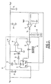
- Switching regulator 10 typically is used for DC-to-DC conversion of an unregulated supply voltage V IN , such as a battery, to a regulated output voltage V OUT for driving a load R L .
- V IN unregulated supply voltage
- V OUT regulated output voltage
- R L is simply shown as a resistor, it may be, for example, a portable communication device or a computer.
- Examples of step-down, non-constant frequency synchronous switching regulators using a one shot timer to control the duty cycle of the switching transistors include the LTC1778, the LTC3711, and the LTC3714, sold by Linear Technology Corporation, of Milpitas, California, and the MAX1710, sold by Maxim Integrated Products, Inc., of Sunnyvale, California.
- the LTC1778, the LTC3711, and the LTC3714 use current-mode control, whereas the MAX1710 uses a hybrid of current-mode and voltage-mode control.
- Switching regulator 10 operates as follows: at the beginning of a cycle, one shot timer 11 generates a pulse that causes driver 12 to turn ON main switching transistor 13 and driver 14 to turn OFF synchronous switching transistor 15. This results in a voltage of approximately V IN -V OUT across inductor 16, causing the current in this inductor to increase.
- the output of one shot timer 11 goes low, causing driver 12 to turn OFF main switching transistor 13 and driver 14 to turn ON synchronous switching transistor 15.
- a voltage of -V OUT is applied across inductor 16, causing the current in this inductor to decrease.
- inductor current flows through synchronous switch 15, it creates a voltage equal to the product of the inductor current and the ON-resistance of switch 15. This voltage is sensed by current amplifier 17 and applied to current comparator 18. When the sense voltage drops below the control voltage V C , the output of current comparator 18 goes high and initiates another pulse from one shot timer 11, thereby repeating the cycle. During the time that synchronous switch 15 is off, blanking circuitry 19 disables the output of current comparator 18. The frequency at which one shot timer 11 operates is referred to as the switching frequency. Inductor 16 and capacitor 24 form a low-pass filter to remove undesirable harmonics of the switching frequency from output voltage V OUT .
- the control voltage V C determines the inductor current through the current-mode loop comprising current sense amplifier 17, current comparator 18, one shot timer 11, and drivers 12 and 14 with switches 13 and 15.
- the control voltage is determined by the voltage error loop comprised of resistor divider 20, error amplifier 21, compensation components 22, and current comparator 18.
- the control voltage V C corresponds to the inductor current valley. If V OUT decreases, the resulting voltage drop at the input of error amplifier 21 causes an increase in the control voltage V C that appears across compensation components 22. This results in an increase in the average inductor current, causing V OUT to increase until the negative input to error amplifier 21 matches the reference. Conversely, if V OUT increases, the control voltage V C is temporarily reduced, decreasing V OUT until the negative input to error amplifier 21 again matches the reference. In this way, the control voltage V C is continuously adjusted such that the output voltage is maintained constant.
- one shot timer 11 allows switching regulator 10 to turn on main switch 13 for a very small amount of time.
- Small and constant switch on-times allow switching regulator 10 to operate at very low duty cycles and convert high input voltages to low output voltages.
- a constant on-time requires that the off-time vary with changes in the input and output voltages as well as with load current. Therefore, the switching frequency will also vary.
- one shot timer 11 accepts V IN and V OUT as inputs to generate an on-time pulse that is proportional to V OUT and inversely proportional to V IN .
- This maintains the switching frequency substantially constant because the on-time changes appropriately as V IN and V OUT vary.
- second order effects such as parasitic resistances and switching losses can cause the required on-time at a particular frequency to deviate from that given by one shot timer 11. The result is that the switching frequency can still vary significantly.
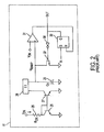
- FIG. 2 a schematic diagram of an illustrative prior art one shot timer to be used in accordance with the synchronous switching voltage regulator of FIG. 1 is described.
- the input voltage V IN of synchronous switching voltage regulator 10 of FIG. 1 is connected to the I ON input of one shot timer 11, while the output voltage V OUT of regulator 10 of FIG. 1 is connected to the V ON input.
- one-shot timer 11 contains input IN and output OUT.
- One shot timer 11 operates as follows. First, the input voltage V IN minus the 0.7V from transistor 26 appears across timing resistor 25 (R ON ). Then, the current I ON through resistor R ON is transferred to timing capacitor 29 through current mirrors 26-27 and 28. While the input IN to one shot timer 11 is low, the current I ON flows out through reset switch 32, causing the output of comparator 31 to be low.
- latch 33 When the input IN to one shot timer 11 goes high, latch 33 is set and its Q output goes high. This turns off switch 32 and sets output OUT high. Because switch 32 is OFF, timing capacitor 29 is charged up by the mirrored current from the I ON input. When the voltage V RAMP across timing capacitor 29 reaches the output voltage V OUT , the output of comparator 31 goes high, thereby resetting latch 33. The result is that one shot timer 11 generates an output pulse that is proportional to V OUT and approximately inversely proportional to V IN .
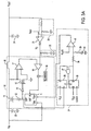
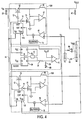
- FIG. 3A a schematic diagram of an exemplary embodiment of the non-constant frequency synchronous switching voltage regulator of FIG. 1 synchronized with a phase locked loop in accordance with the principles of the present invention is described.
- switching voltage regulator 10 of FIG. 1 is synchronized with phase locked loop 34 to control the on-time of one shot timer 11 so that the switching frequency is locked to a reference clock.
- phase locked loop 34 to control the on-time of one shot timer 11 so that the switching frequency is locked to a reference clock.
- Phase locked loop 34 includes AND gate 37 and data flip flops 35 and 36.
- flip flop outputs are both zero, a rising edge from CLOCK sets flip flop 36, and a subsequent rising edge from the OUT output of one shot timer 11 sets flip flop 35.
- AND gate 37 causes both flip flops 35 and 36 to reset.
- the output of flip flop 36 is a square wave having a rising edge corresponding to the rising edge of the clock and whose falling edge corresponds to the rising edge from the OUT output of one shot timer 11.
- a loop filter comprising resistors 38 and 39, and capacitor 40 provides an average DC value from the output of flip flop 36.
- the on-time of one shot timer 11 is controlled as follows. When the duty cycle of flip flop 36 is less than 50%, the average DC value provided by flip flop 36 is less than V cc /2, causing amplifier 41 to increase the V ON input to one shot timer 11.
- the on-time of switching regulator 10 is increased as described above in connection with FIG. 2. A longer on-time increases the phase delay between CLOCK and the OUT output of one-shot timer 11 as well as the duty cycle of flip flop 36. Analogously, when the duty cycle of flip flop 36 is greater than 50%, the output of amplifier 41 is reduced. Consequently, the on-time of switching regulator 10 decreases. The phase delay between the reference clock and the OUT output of one shot timer 11 also decreases. Phase locked loop 34 therefore continuously adjusts the on-time of one shot timer 11 to maintain the duty cycle of flip flop 36 at 50%. This maintains switching regulator 10 at the same frequency as CLOCK with a 180° phase delay.
- phase locked loop 34 controls the I ON input of one shot timer 11 rather than the V ON input as in the circuit in FIG. 3A.
- the polarity of the inputs to amplifier 41 have also been reversed.
- the duty cycle of flip flop 36 is less than 50%, the output of amplifier 41 decreases, causing a corresponding decrease in the voltage at the I ON input of one shot timer 11. This increases the on-time of switching regulator 10.
- switching regulator 10 is kept at the same frequency as CLOCK with a 180° phase delay.
- phase locked loop 34 is used to synchronize switching regulator 10 of FIG. 1, it will be understood by one skilled in the art that phase locked loop 34 may be used to synchronize other types of non-constant frequency switching regulator circuits, including synchronous and non-synchronous regulators, such as boost (step-up), buck (step-down), or buck-boost switching regulators, with constant on-time or constant off-time, and using any of several other control techniques.
- control techniques include current-mode control with other current sense elements such as a sense resistor or current sense transformer in a variety of locations, voltage-mode control, as well as hybrid control techniques such as sensing based on output capacitor voltage change. Examples of switching regulators using hybrid control techniques include the MAX1710, sold by Maxim Integrated Products, Inc., of Sunnyvale, California, and the CS5120, sold by ON Semiconductor, of Phoenix, AZ.
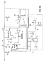
- Switching voltage regulators 10A and 10B operate independently and are connected in parallel, sharing common input capacitor 23, common output capacitor 42, and common current control voltage V C set by feedback network 43, error amplifier 44, and compensation network 45.
- the output OUT of one shot timer 11B of switching regulator 10B forms the CLOCK input to phase locked loop 46.
- Phase locked loop 46 controls the on-time of switching regulator 10A in the same manner as described above in FIG. 3A.
- switching regulator 10A and switching regulator 10B operate at the same constant switching frequency with a 180° phase delay.
- the system forms a two-phase switching voltage regulator with reduced input and output ripple currents as well as reduced inductor size and capacitance when compared to a single switching voltage regulator.
- phase locked loop 46 may be used to synchronize other types of non-constant frequency switching regulator circuits, including synchronous and non-synchronous regulators, such as boost (step-up), buck (step-down), or buck-boost switching regulators, with constant on-time, constant off-time, or hysteretic control, and using any of several other control techniques.
- control techniques include current-mode control with other current sense elements such as a sense resistor or current sense transformer in a variety of locations, voltage-mode control, as well as hybrid control techniques such as sensing based on output capacitor voltage change.
- phase locked loop 46 may be used to synchronize a plurality of switching regulator circuits to form multiple power converters having two or more phases, multiple inputs and a single output, and multiple outputs with a single input.
Landscapes
- Engineering & Computer Science (AREA)
- Power Engineering (AREA)
- Dc-Dc Converters (AREA)
- Stabilization Of Oscillater, Synchronisation, Frequency Synthesizers (AREA)
Applications Claiming Priority (2)
| Application Number | Priority Date | Filing Date | Title |
|---|---|---|---|
| US827872 | 2001-04-06 | ||
| US09/827,872 US6476589B2 (en) | 2001-04-06 | 2001-04-06 | Circuits and methods for synchronizing non-constant frequency switching regulators with a phase locked loop |
Publications (3)
| Publication Number | Publication Date |
|---|---|
| EP1248352A2 true EP1248352A2 (fr) | 2002-10-09 |
| EP1248352A3 EP1248352A3 (fr) | 2004-03-31 |
| EP1248352B1 EP1248352B1 (fr) | 2008-02-06 |
Family
ID=25250385
Family Applications (1)
| Application Number | Title | Priority Date | Filing Date |
|---|---|---|---|
| EP02007264A Expired - Lifetime EP1248352B1 (fr) | 2001-04-06 | 2002-03-28 | Circuits et procédés pour la synchronisation des régulateurs à découpage à fréquence non-constante avec une boucle de verrouillage de phase |
Country Status (6)
| Country | Link |
|---|---|
| US (3) | US6476589B2 (fr) |
| EP (1) | EP1248352B1 (fr) |
| JP (1) | JP4056780B2 (fr) |
| AT (1) | ATE385623T1 (fr) |
| DE (1) | DE60224896T2 (fr) |
| TW (1) | TW554613B (fr) |
Cited By (3)
| Publication number | Priority date | Publication date | Assignee | Title |
|---|---|---|---|---|
| EP1531538A2 (fr) | 2003-11-11 | 2005-05-18 | Leopold Kostal GmbH & Co. KG | Procédé de commande d'un convertisseur élévateur, convertisseur élévateur multiphasé et son utilisation |
| US8680831B2 (en) | 2011-04-01 | 2014-03-25 | Richtek Technology Corp | Constant frequency on-time control system and method and voltage regulator using the same |
| US8912775B2 (en) | 2011-04-12 | 2014-12-16 | Infineon Technologies Ag | Power factor correction circuit having multiple switched-mode converter circuits |
Families Citing this family (117)
| Publication number | Priority date | Publication date | Assignee | Title |
|---|---|---|---|---|
| US6476589B2 (en) * | 2001-04-06 | 2002-11-05 | Linear Technology Corporation | Circuits and methods for synchronizing non-constant frequency switching regulators with a phase locked loop |
| DE10125334A1 (de) * | 2001-05-23 | 2002-12-05 | Infineon Technologies Ag | Gleichspannungswandler mit Schaltregler |
| US20030016545A1 (en) * | 2001-06-05 | 2003-01-23 | Bel-Fuse, Inc. | Buck regulator with adaptive auxiliary voltage flyback regulator |
| US6667602B2 (en) * | 2002-03-08 | 2003-12-23 | Visteon Global Technologies, Inc. | Low frequency switching voltage pre-regulator |
| US6664774B2 (en) * | 2002-03-27 | 2003-12-16 | Semtech Corporation | Offset peak current mode control circuit for multiple-phase power converter |
| AU2003220665A1 (en) * | 2002-04-03 | 2003-10-20 | International Rectifier Corporation | Synchronous buck converter improvements |
| JP3742780B2 (ja) * | 2002-05-09 | 2006-02-08 | 松下電器産業株式会社 | Dc−dcコンバータ |
| US6670794B1 (en) * | 2002-07-12 | 2003-12-30 | Richtek Technology Corp. | Multi-phase DC-to-DC buck converter with multi-phase current balance and adjustable load regulation |
| US7020786B2 (en) * | 2002-07-23 | 2006-03-28 | Dell Products L.P. | System and method for selecting a voltage output reference |
| US7058374B2 (en) * | 2002-10-15 | 2006-06-06 | Skyworks Solutions, Inc. | Low noise switching voltage regulator |
| US7394445B2 (en) | 2002-11-12 | 2008-07-01 | Power-One, Inc. | Digital power manager for controlling and monitoring an array of point-of-load regulators |
| US7456617B2 (en) | 2002-11-13 | 2008-11-25 | Power-One, Inc. | System for controlling and monitoring an array of point-of-load regulators by a host |
| US6833691B2 (en) | 2002-11-19 | 2004-12-21 | Power-One Limited | System and method for providing digital pulse width modulation |
| US7882372B2 (en) | 2002-12-21 | 2011-02-01 | Power-One, Inc. | Method and system for controlling and monitoring an array of point-of-load regulators |
| US7836322B2 (en) | 2002-12-21 | 2010-11-16 | Power-One, Inc. | System for controlling an array of point-of-load regulators and auxiliary devices |
| US7266709B2 (en) | 2002-12-21 | 2007-09-04 | Power-One, Inc. | Method and system for controlling an array of point-of-load regulators and auxiliary devices |
| US7249267B2 (en) | 2002-12-21 | 2007-07-24 | Power-One, Inc. | Method and system for communicating filter compensation coefficients for a digital power control system |
| US7673157B2 (en) | 2002-12-21 | 2010-03-02 | Power-One, Inc. | Method and system for controlling a mixed array of point-of-load regulators through a bus translator |
| US7737961B2 (en) | 2002-12-21 | 2010-06-15 | Power-One, Inc. | Method and system for controlling and monitoring an array of point-of-load regulators |
| US7743266B2 (en) | 2002-12-21 | 2010-06-22 | Power-One, Inc. | Method and system for optimizing filter compensation coefficients for a digital power control system |
| TWI234058B (en) * | 2003-01-02 | 2005-06-11 | Richtek Techohnology Corp | Switching type voltage regulator and its method |
| US7023190B2 (en) | 2003-02-10 | 2006-04-04 | Power-One, Inc. | ADC transfer function providing improved dynamic regulation in a switched mode power supply |
| US7710092B2 (en) | 2003-02-10 | 2010-05-04 | Power-One, Inc. | Self tracking ADC for digital power supply control systems |
| US6936999B2 (en) | 2003-03-14 | 2005-08-30 | Power-One Limited | System and method for controlling output-timing parameters of power converters |
| JP3710454B2 (ja) * | 2003-03-31 | 2005-10-26 | Tdk株式会社 | 電源装置及びその制御装置 |
| US6819577B1 (en) | 2003-05-19 | 2004-11-16 | Texas Instruments Incorporated | Distributing clock and programming phase shift in multiphase parallelable converters |
| ITMI20031315A1 (it) * | 2003-06-27 | 2004-12-28 | St Microelectronics Srl | Dispositivo per la correzione del fattore di potenza in alimentatori a commutazione forzata. |
| US6906499B2 (en) * | 2003-06-27 | 2005-06-14 | Seagate Technology Llc | Current mode bang-bang controller in a switching voltage regulator |
| WO2005022735A1 (fr) * | 2003-08-27 | 2005-03-10 | Fraunhofer-Gesellschaft zur Förderung der angewandten Forschung e.V. | Dispositif de commande servant a commander un commutateur de charge dans un regulateur a decoupage et procede pour commander un commutateur de charge |
| US7313176B1 (en) * | 2003-09-11 | 2007-12-25 | Xilinx, Inc. | Programmable on chip regulators with bypass |
| US7532542B2 (en) * | 2004-01-20 | 2009-05-12 | Shotspotter, Inc. | System and method for improving the efficiency of an acoustic sensor |
| US7250746B2 (en) * | 2004-03-31 | 2007-07-31 | Matsushita Electric Industrial Co., Ltd. | Current mode switching regulator with predetermined on time |
| US7199636B2 (en) * | 2004-03-31 | 2007-04-03 | Matsushita Electric Industrial Co., Ltd. | Active diode |
| US7405497B2 (en) * | 2004-04-13 | 2008-07-29 | Electrovaya Inc. | Integrated power supply system |
| US7268526B1 (en) * | 2004-04-21 | 2007-09-11 | National Semiconductor Corporation | Switch mode power supply control circuit |
| US7372238B1 (en) * | 2004-04-29 | 2008-05-13 | National Semiconductor Corporation | Apparatus and method for step-down switching voltage regulation |
| US7045993B1 (en) * | 2004-04-29 | 2006-05-16 | National Semiconductor Corporation | Apparatus and method for step-down switching voltage regulation |
| US7045992B1 (en) | 2004-06-22 | 2006-05-16 | National Semiconductor Corporation | Apparatus and method for start-up for a synchronous switching regulator |
| US6956361B1 (en) * | 2004-07-14 | 2005-10-18 | Delphi Technologies, Inc. | DC/DC converter employing synchronous rectification |
| US7282894B2 (en) * | 2004-08-25 | 2007-10-16 | Matsushita Electric Industrial Co., Ltd. | Method and apparatus for performing lossless sensing and negative inductor currents in a high side switch |
| JP4630763B2 (ja) * | 2004-08-25 | 2011-02-09 | パナソニック株式会社 | 固定周波数電流モードのスイッチングレギュレータにおける高次の傾き補償 |
| US7282900B2 (en) * | 2004-08-25 | 2007-10-16 | Matsushita Electric Industrial Co., Ltd. | Performance controller for a step down current mode switching regulator |
| JP2006067730A (ja) * | 2004-08-27 | 2006-03-09 | Sanken Electric Co Ltd | 力率改善回路 |
| TWI242928B (en) * | 2004-09-10 | 2005-11-01 | Richtek Techohnology Corp | Electronic circuit using normally-on junction field effect transistor |
| US7579819B1 (en) | 2004-11-10 | 2009-08-25 | National Semiconductor Corporation | Apparatus and method for flywheel current injection for a regulator |
| US7221134B1 (en) * | 2004-11-10 | 2007-05-22 | National Semiconductor Corporation | Apparatus and method for flywheel current injection for a regulator |
| JP4832056B2 (ja) * | 2004-11-18 | 2011-12-07 | パナソニック株式会社 | 高効率高スルーレートのスイッチングレギュレータ/アンプ |
| JP2006158097A (ja) * | 2004-11-30 | 2006-06-15 | Renesas Technology Corp | 電源制御用半導体集積回路および電子部品並びに電源装置 |
| US7071664B1 (en) * | 2004-12-20 | 2006-07-04 | Texas Instruments Incorporated | Programmable voltage regulator configurable for double power density and reverse blocking |
| US7394231B2 (en) * | 2005-02-08 | 2008-07-01 | Linear Technology Corporation | Current-mode control for switched step up-step down regulators |
| US7256570B2 (en) * | 2005-02-08 | 2007-08-14 | Linear Technology Corporation | Light load current-mode control for switched step up-step down regulators |
| US7466112B2 (en) * | 2005-02-08 | 2008-12-16 | Linear Technology Corporation | Variable frequency current-mode control for switched step up-step down regulators |
| US7365525B2 (en) | 2005-02-08 | 2008-04-29 | Linear Technology Corporation | Protection for switched step up/step down regulators |
| US7602158B1 (en) * | 2005-03-21 | 2009-10-13 | National Semiconductor Corporation | Power circuit for generating non-isolated low voltage power in a standby condition |
| US7919952B1 (en) * | 2005-03-21 | 2011-04-05 | Microsemi Corporation | Automatic gain control technique for current monitoring in current-mode switching regulators |
| US20060215680A1 (en) * | 2005-03-28 | 2006-09-28 | Camagna John R | Method for high voltage power feed on differential cable pairs |
| US7239115B2 (en) | 2005-04-04 | 2007-07-03 | Power-One, Inc. | Digital pulse width modulation controller with preset filter coefficients |
| US7327149B2 (en) | 2005-05-10 | 2008-02-05 | Power-One, Inc. | Bi-directional MOS current sense circuit |
| US7425819B2 (en) * | 2005-06-16 | 2008-09-16 | Microsemi Corporation | Slope compensation circuit |
| US7391199B2 (en) * | 2005-07-20 | 2008-06-24 | Matsushita Electric Industrial Co., Ltd. | DC-DC converter |
| US7688046B2 (en) * | 2005-07-25 | 2010-03-30 | Apple Inc. | Power converters having varied switching frequencies |
| US7342383B1 (en) | 2005-11-07 | 2008-03-11 | National Semiconductor Corporation | Apparatus and method for smooth DCM-to-CCM transition in a multi-phase DC-DC converter |
| US7466569B2 (en) * | 2005-11-16 | 2008-12-16 | System General Corporation | Power converter having phase lock circuit for quasi-resonant soft switching |
| JP4493045B2 (ja) * | 2005-12-05 | 2010-06-30 | パナソニック株式会社 | スイッチングレギュレータ回路 |
| US7528587B2 (en) * | 2005-12-27 | 2009-05-05 | Linear Technology Corporation | Switched converter with variable peak current and variable off-time control |
| JP4753729B2 (ja) * | 2006-01-27 | 2011-08-24 | パナソニック株式会社 | スイッチング制御回路 |
| TWI308996B (en) * | 2006-03-22 | 2009-04-21 | Anpec Electronics Corp | Switching regulator capable of fixing frequency |
| US7498864B2 (en) * | 2006-04-04 | 2009-03-03 | Freescale Semiconductor, Inc. | Electronic fuse for overcurrent protection |
| TWI319134B (en) * | 2006-06-16 | 2010-01-01 | Mitac Int Corp | Power switch device and method for cluster computer |
| US7495424B1 (en) * | 2006-08-11 | 2009-02-24 | National Semiconductor Corporation | Overload compensation circuit with improved recovery response for a power supply |
| US20080084239A1 (en) * | 2006-09-08 | 2008-04-10 | Matsushita Electric Industrial Co., Ltd. | Regulated charge pump circuit |
| JP4629648B2 (ja) * | 2006-11-28 | 2011-02-09 | ザインエレクトロニクス株式会社 | コンパレータ方式dc−dcコンバータ |
| US7598715B1 (en) | 2007-04-04 | 2009-10-06 | National Semiconductor Corporation | Apparatus and method for reverse current correction for a switching regulator |
| US8446136B2 (en) * | 2007-04-13 | 2013-05-21 | Advanced Analogic Technologies, Inc. | Pseudo fixed frequency switch-mode DC/DC voltage regulator control method |
| US7936160B1 (en) | 2007-04-25 | 2011-05-03 | National Semiconductor Corporation | Apparatus and method for valley emulated current mode control |
| TW200903959A (en) * | 2007-07-13 | 2009-01-16 | Richtek Technology Corp | Switching voltage converter capable of covering switching noise and the method thereof |
| US8350546B2 (en) * | 2007-08-15 | 2013-01-08 | Advanced Analogic Technologies, Inc. | High voltage SEPIC converter |
| US7737668B2 (en) * | 2007-09-07 | 2010-06-15 | Panasonic Corporation | Buck-boost switching regulator |
| US7683719B2 (en) * | 2007-09-07 | 2010-03-23 | Panasonic Corporation | Internal frequency compensation circuit for integrated circuit controllers |
| US7834613B2 (en) | 2007-10-30 | 2010-11-16 | Power-One, Inc. | Isolated current to voltage, voltage to voltage converter |
| US7679341B2 (en) * | 2007-12-12 | 2010-03-16 | Monolithic Power Systems, Inc. | External control mode step down switching regulator |
| US7923974B2 (en) * | 2008-01-04 | 2011-04-12 | Chil Semiconductor Corporation | Modification of switch activation order in a power supply |
| US7868595B1 (en) * | 2008-06-17 | 2011-01-11 | National Semiconductor Corporation | Apparatus and method for soft-start mode transition in a switching regulator |
| US20100045245A1 (en) * | 2008-08-19 | 2010-02-25 | Advanced Analogic Technologies, Inc. | Control Method for DC/DC Converters and Switching Regulators |
| JP5093037B2 (ja) * | 2008-10-03 | 2012-12-05 | サンケン電気株式会社 | 負荷駆動回路 |
| US8203320B2 (en) * | 2009-01-07 | 2012-06-19 | Linear Technology Corporation | Switching mode converters |
| US8188723B2 (en) * | 2009-01-22 | 2012-05-29 | Infineon Technologies Ag | Switching converter and method to control a switching converter |
| JP5402469B2 (ja) * | 2009-09-28 | 2014-01-29 | サンケン電気株式会社 | 電力変換装置及び制御回路 |
| US8258767B2 (en) * | 2010-01-13 | 2012-09-04 | Alpha & Omega Semiconductor, Inc. | Power conversion system and power control method for reducing cross regulation effect |
| US8330441B1 (en) * | 2010-01-25 | 2012-12-11 | National Semiconductor Corporation | Technique for reducing crosstalk interference between integrated switching regulators |
| US9397571B2 (en) | 2010-06-23 | 2016-07-19 | Volterra Semiconductor Corporation | Controlled delivery of a charging current to a boost capacitor of a voltage regulator |
| US9203301B2 (en) | 2010-06-23 | 2015-12-01 | Volterra Semiconductor Corporation | Feedback for controlling the switching frequency of a voltage regulator |
| US8629669B2 (en) | 2010-07-27 | 2014-01-14 | Volterra Semiconductor Corporation | Sensing and feedback in a current mode control voltage regulator |
| JP2012050191A (ja) * | 2010-08-25 | 2012-03-08 | Rohm Co Ltd | スイッチングレギュレータ |
| TWI427908B (zh) * | 2010-12-30 | 2014-02-21 | Realtek Semiconductor Corp | 單電感雙輸出電源轉換器與其驅動方法 |
| JP5772191B2 (ja) | 2011-04-28 | 2015-09-02 | ミツミ電機株式会社 | スイッチング電源装置 |
| US8953341B2 (en) | 2011-05-09 | 2015-02-10 | Infineon Technologies Ag | Converter with reduced power consumption |
| KR101832409B1 (ko) | 2011-05-17 | 2018-02-27 | 삼성디스플레이 주식회사 | 게이트 구동부 및 이를 포함하는 액정 표시 장치 |
| US8643350B2 (en) * | 2011-06-11 | 2014-02-04 | Shenzhen China Star Optoelectronics Technology Co., Ltd. | Self-driven synchronous rectification boost converter having high step-up ratio |
| JP5752513B2 (ja) * | 2011-07-29 | 2015-07-22 | ブラザー工業株式会社 | 電源システム、それを備えた画像形成装置 |
| JP5834790B2 (ja) * | 2011-11-09 | 2015-12-24 | ブラザー工業株式会社 | 電源システム、同電源システムを備えた画像形成装置および電源システムの制御方法 |
| TWI446699B (zh) * | 2011-12-27 | 2014-07-21 | Richtek Technology Corp | 具有降壓調節能力的升壓轉換器及其降壓調節方法 |
| US9195246B2 (en) | 2012-02-09 | 2015-11-24 | Volterra Semiconductor Corporation | Virtual output voltage sensing for feed-forward control of a voltage regulator |
| US8957655B2 (en) * | 2012-03-16 | 2015-02-17 | Micrel, Inc. | Last gasp hold-up circuit using adaptive constant on time control |
| US9281747B2 (en) | 2012-06-26 | 2016-03-08 | Volterra Semiconductor Corporation | Voltage regulator control using information from a load |
| CN102751874B (zh) * | 2012-06-27 | 2015-01-07 | 电子科技大学 | 自适应恒定导通时间控制电路 |
| EP2750276A1 (fr) | 2012-12-28 | 2014-07-02 | Dialog Semiconductor GmbH | Convertisseur abaisseur de tension à mode de courant contrôlé à boucle à verrouillage de phase |
| JP6304577B2 (ja) | 2013-01-31 | 2018-04-04 | ブラザー工業株式会社 | 電源システム、同電源システムを備えた画像形成装置および電源システムの制御方法 |
| JP6111705B2 (ja) | 2013-02-01 | 2017-04-12 | ブラザー工業株式会社 | 電源システム |
| JP6020219B2 (ja) | 2013-02-06 | 2016-11-02 | ブラザー工業株式会社 | 電源システム |
| JP6044380B2 (ja) | 2013-02-18 | 2016-12-14 | ブラザー工業株式会社 | 電源システム、同電源システムを備えた画像形成装置 |
| CN105322766B (zh) | 2014-06-13 | 2018-09-07 | 立锜科技股份有限公司 | 固定导通或固定关闭时间切换式电源供应器及其控制电路 |
| US9748842B1 (en) * | 2016-07-18 | 2017-08-29 | Texas Instruments Incorporated | Sense circuit for voltage converter |
| US10218366B1 (en) | 2017-11-27 | 2019-02-26 | Linear Technology Holding Llc | Phase locked loop calibration for synchronizing non-constant frequency switching regulators |
| US11081963B2 (en) * | 2019-11-27 | 2021-08-03 | Infineon Technologies Austria Ag | Slope detection and correction for current sensing using on-state resistance of a power switch |
| US11289998B2 (en) | 2020-07-31 | 2022-03-29 | Texas Instruments Incorporated | Current limiting technique for buck converters |
| US11223276B1 (en) * | 2020-10-30 | 2022-01-11 | Monolithic Power Systems, Inc. | Adaptive constant on time converter and the method thereof |
Citations (5)
| Publication number | Priority date | Publication date | Assignee | Title |
|---|---|---|---|---|
| EP0090237A2 (fr) * | 1982-03-30 | 1983-10-05 | FIAR FABBRICA ITALIANA APPARECCHIATURE RADIOELETTRICHE S.p.A. | Dispositif électronique de commande de tension |
| US4929882A (en) * | 1987-06-23 | 1990-05-29 | National Semiconductor Corporation | Apparatus for converting DC to DC having non-feed back variable hysteretic current-mode control for maintaining approximately constant frequency |
| US5045712A (en) * | 1985-03-28 | 1991-09-03 | Raytheon Company | Synchronized switched mode power supplies |
| US5130561A (en) * | 1990-08-29 | 1992-07-14 | Alcatel Network Systems, Inc. | Switching mode power supplies with controlled synchronization |
| US5929620A (en) * | 1996-11-07 | 1999-07-27 | Linear Technology Corporation | Switching regulators having a synchronizable oscillator frequency with constant ramp amplitude |
Family Cites Families (96)
| Publication number | Priority date | Publication date | Assignee | Title |
|---|---|---|---|---|
| US3458798A (en) | 1966-09-15 | 1969-07-29 | Ibm | Solid state rectifying circuit arrangements |
| DE1638009B2 (de) | 1968-01-23 | 1972-08-24 | Danfoss A/S, Nordborg (Danemark) | Gleichspannungsgespeiste, geregelte gleichspannungsversorgung |
| US3571697A (en) | 1968-12-16 | 1971-03-23 | Collins Radio Co | Variable impedance switching regulator |
| US3581186A (en) | 1969-03-19 | 1971-05-25 | Motorola Inc | Reduced forward voltage drop rectifying circuit |
| US3579091A (en) | 1969-05-16 | 1971-05-18 | Bell Telephone Labor Inc | Switching regulator with random noise generator |
| US3582758A (en) | 1969-09-30 | 1971-06-01 | Ibm | Rectifier using low saturation voltage transistors |
| US3772588A (en) | 1971-10-01 | 1973-11-13 | Cogar Corp | Dual control loop switching regulator |
| US3733540A (en) | 1972-02-03 | 1973-05-15 | Motorola Inc | Switching regulator sweep starting protection circuit |
| US3725766A (en) * | 1972-08-17 | 1973-04-03 | Lorain Prod Corp | Frequency compensating circuit for voltage regulators |
| US3784893A (en) | 1973-01-10 | 1974-01-08 | Bell Telephone Labor Inc | High voltage shutdown protection circuit with bias arrangement to decrease the voltage shutdown point with increasing load |
| FR2220114B1 (fr) | 1973-03-01 | 1976-11-05 | Silec Semi Conducteurs | |
| US3863128A (en) | 1973-07-30 | 1975-01-28 | Honeywell Inc | Voltage monitoring controlling and protecting apparatus employing programmable unijunction transistor |
| US3879647A (en) | 1974-06-07 | 1975-04-22 | Bell Telephone Labor Inc | DC to DC converter with regulation having accelerated soft start into active control region of regulation and fast response overcurrent limiting features |
| US4013939A (en) | 1974-12-30 | 1977-03-22 | Trw Inc. | Multiple feedback control apparatus for power conditioning equipment |
| US4035710A (en) | 1975-10-20 | 1977-07-12 | International Business Machines Corporation | Pulse width modulated voltage regulator-converter/power converter having means for improving the static stability characteristics thereof |
| US4071884A (en) | 1976-06-14 | 1978-01-31 | Micro Components Corporation | Integrated circuit high voltage DC converter |
| US4160288A (en) | 1978-05-17 | 1979-07-03 | Communications Satellite Corp. | Active filter circuit for regulated dc to dc power supplies |
| US4309650A (en) | 1979-06-18 | 1982-01-05 | Bell Telephone Laboratories, Incorporated | Average current controlled switching regulator utilizing digital control techniques |
| US4326245A (en) | 1981-02-23 | 1982-04-20 | Siemens Corporation | Current foldback circuit for a DC power supply |
| US4462069A (en) | 1981-08-14 | 1984-07-24 | American Standard Inc. | d.c. To d.c. voltage regulator having an input protection circuit, a d.c. to d.c. inverter, a saturable reactor regulator, and main and auxiliary rectifying and filtering circuits |
| US4395675A (en) | 1981-10-22 | 1983-07-26 | Bell Telephone Laboratories, Incorporated | Transformerless noninverting buck boost switching regulator |
| US4428015A (en) | 1981-12-22 | 1984-01-24 | Hughes Aircraft Company | Overcurrent limiter circuit for switching regulator power supplies |
| US4458199A (en) | 1982-02-04 | 1984-07-03 | Varo, Inc. | Link regulator with feed forward switching control |
| US4479174A (en) | 1982-11-03 | 1984-10-23 | Reliance Electric Company | Efficiency increasing circuit for switching power supplies operating at low power levels |
| US4566769A (en) | 1982-12-29 | 1986-01-28 | Olympus Optical Co., Ltd. | Power supply unit for electronic flash |
| US4493017A (en) | 1983-01-24 | 1985-01-08 | Reliance Electric Company | Single drive transformer with regenerative winding for p.w.m. supply having alternately conducting power devices |
| US4554499A (en) | 1983-05-03 | 1985-11-19 | Genentech, Inc. | Computer controlled motor |
| JPS6032565A (ja) | 1983-07-30 | 1985-02-19 | Matsushita Electric Works Ltd | 電源回路 |
| US4541041A (en) | 1983-08-22 | 1985-09-10 | General Electric Company | Full load to no-load control for a voltage fed resonant inverter |
| US4519024A (en) | 1983-09-02 | 1985-05-21 | At&T Bell Laboratories | Two-terminal transistor rectifier circuit arrangement |
| US4634892A (en) | 1984-01-16 | 1987-01-06 | National Semiconductor Corporation | Pulse width modulator circuit for switching regulators |
| JPS60156269A (ja) | 1984-01-25 | 1985-08-16 | Fujitsu Ltd | 直流−直流コンバ−タ |
| US4578630A (en) | 1984-11-23 | 1986-03-25 | At&T Bell Laboratories | Buck boost switching regulator with duty cycle limiting |
| US4716514A (en) | 1984-12-13 | 1987-12-29 | Unitrode Corporation | Synchronous power rectifier |
| US4634956A (en) | 1985-01-10 | 1987-01-06 | Motorola, Inc. | DC to DC converter |
| US4706177A (en) | 1985-11-14 | 1987-11-10 | Elliot Josephson | DC-AC inverter with overload driving capability |
| DE3541308C1 (en) | 1985-11-22 | 1987-02-05 | Philips Patentverwaltung | DC power supply generator e.g. for gas discharge lamp - obtains regulated DC from mains supply giving sinusoidal input to filter and rectifier |
| DE3541307C1 (en) | 1985-11-22 | 1987-02-05 | Philips Patentverwaltung | DC power supply generator e.g. for gas discharge lamp - obtains regulated DC voltage from mains supply giving sinusoidal input to filter and rectifier |
| US4674020A (en) | 1985-12-13 | 1987-06-16 | Siliconix Incorporated | Power supply having dual ramp control circuit |
| US4672518A (en) | 1986-07-30 | 1987-06-09 | American Telephone And Telegraph Co., At&T Bell Labs | Current mode control arrangement with load dependent ramp signal added to sensed current waveform |
| US4727308A (en) | 1986-08-28 | 1988-02-23 | International Business Machines Corporation | FET power converter with reduced switching loss |
| US4672303A (en) | 1986-08-28 | 1987-06-09 | International Business Machines Corporation | Inductor current control circuit |
| US4683529A (en) | 1986-11-12 | 1987-07-28 | Zytec Corporation | Switching power supply with automatic power factor correction |
| US4823070A (en) | 1986-11-18 | 1989-04-18 | Linear Technology Corporation | Switching voltage regulator circuit |
| US4709315A (en) | 1986-11-24 | 1987-11-24 | Rockwell International Corporation | Isolated controller circuit |
| US4801859A (en) | 1986-12-23 | 1989-01-31 | Sundstrand Corporation | Boost/buck DC/DC converter |
| US4754385A (en) | 1987-01-30 | 1988-06-28 | Varo, Inc. | Two transistor flyback switching converter with current sensing for discontinuous operation |
| US4928200A (en) | 1987-04-02 | 1990-05-22 | Cherry Semiconductor Corporation | Overcurrent protection for switching mode power converter |
| US4819122A (en) | 1987-04-02 | 1989-04-04 | Cherry Semiconductor Corporation | Over-current timer modulator |
| DE3717815A1 (de) | 1987-05-27 | 1988-12-15 | Bayer Ag | Fungizide mittel auf basis von substituierten cyanamiden |
| JPS63307510A (ja) | 1987-06-09 | 1988-12-15 | Seiko Instr & Electronics Ltd | シリ−ズボルテ−ジレギュレ−タ逆流防止回路 |
| US4813066A (en) | 1987-07-13 | 1989-03-14 | American Telephone And Telegraph Company, At&T Information Systems | Battery feed circuit for a telephone system |
| US4814684A (en) | 1987-09-30 | 1989-03-21 | Trw Inc. | Apparatus for extending the Vout/Vin ratio of a DC-to-DC converter |
| US4837495A (en) | 1987-10-13 | 1989-06-06 | Astec U.S.A. (Hk) Limited | Current mode converter with controlled slope compensation |
| US4843532A (en) | 1988-07-01 | 1989-06-27 | General Electric Company | Regulating pulse width modulator for power supply with high speed shutoff |
| US4870555A (en) | 1988-10-14 | 1989-09-26 | Compaq Computer Corporation | High-efficiency DC-to-DC power supply with synchronous rectification |
| US4866587A (en) | 1988-12-22 | 1989-09-12 | American Telephone And Telegraph Company At&T Bell Laboratories | Electronic ringing signal generator |
| US4922404A (en) | 1989-03-15 | 1990-05-01 | General Electric Company | Method and apparatus for gating of synchronous rectifier |
| JP2686135B2 (ja) | 1989-03-28 | 1997-12-08 | 松下電工株式会社 | 定電流電源回路 |
| US4884183A (en) | 1989-03-29 | 1989-11-28 | General Electric Company | Dual-mode controlled pulse width modulator |
| US4902957A (en) | 1989-04-27 | 1990-02-20 | International Business Machines Corporation | DC/DC converter |
| DE3914799A1 (de) | 1989-05-05 | 1990-11-08 | Standard Elektrik Lorenz Ag | Durchflusswandler |
| US4931716A (en) | 1989-05-05 | 1990-06-05 | Milan Jovanovic | Constant frequency zero-voltage-switching multi-resonant converter |
| US5028861A (en) | 1989-05-24 | 1991-07-02 | Motorola, Inc. | Strobed DC-DC converter with current regulation |
| US5184129A (en) | 1989-09-13 | 1993-02-02 | Advanced Micro Devices, Inc. | Switchable DAC with current surge protection |
| JPH03113986A (ja) | 1989-09-27 | 1991-05-15 | Toshiba Corp | カメラエンコーダシステム |
| US5066900A (en) | 1989-11-14 | 1991-11-19 | Computer Products, Inc. | Dc/dc converter switching at zero voltage |
| US4996638A (en) | 1990-02-15 | 1991-02-26 | Northern Telecom Limited | Method of feedback regulating a flyback power converter |
| JPH0442771A (ja) | 1990-06-06 | 1992-02-13 | Fujitsu Ltd | 高効率型dc/dcコンバータ |
| JP2682202B2 (ja) | 1990-06-08 | 1997-11-26 | 日本電気株式会社 | 電界効果トランジスタを用いた整流回路 |
| FR2663169A1 (fr) | 1990-06-08 | 1991-12-13 | Alcatel Espace | Dispositif de regulation d'un parametre par une structure bidirectionnelle en courant. |
| JP2681409B2 (ja) | 1990-06-19 | 1997-11-26 | ファナック株式会社 | Dc―dcコンバータ |
| JPH0488870A (ja) | 1990-07-30 | 1992-03-23 | Nec Corp | スイッチングレギュレータ回路 |
| JPH04101286A (ja) | 1990-08-21 | 1992-04-02 | Toshiba Corp | ナンバプレート情報読取装置 |
| JPH0780346B2 (ja) | 1990-09-19 | 1995-08-30 | 凸版印刷株式会社 | サインパネル及びサインパネルの製造方法 |
| JPH04175908A (ja) | 1990-11-09 | 1992-06-23 | Mitsubishi Electric Corp | スイッチング・レギュレータ |
| US5081411A (en) | 1990-12-20 | 1992-01-14 | Honeywell Inc. | AC/DC two-wire control techniques |
| US5134355A (en) | 1990-12-31 | 1992-07-28 | Texas Instruments Incorporated | Power factor correction control for switch-mode power converters |
| US5068575A (en) | 1991-02-21 | 1991-11-26 | Eastman Kodak Company | Indirect storage capacitor voltage sensing means for a flyback type DC-to-DC converter |
| US5237606A (en) | 1991-05-01 | 1993-08-17 | Charles Industries, Ltd. | Enhanced synchronous rectifier |
| US5097196A (en) | 1991-05-24 | 1992-03-17 | Rockwell International Corporation | Zero-voltage-switched multiresonant DC to DC converter |
| US5309078A (en) | 1991-07-11 | 1994-05-03 | Sgs-Thomson Microelectronics, Inc. | Synchronous rectification method for reducing power dissipation in motor drivers in PWM mode |
| US5177676A (en) | 1991-09-27 | 1993-01-05 | Exide Electronics Corporation | Voltage source with enhanced source impedance control |
| US5179511A (en) | 1991-10-16 | 1993-01-12 | Illinois Institute Of Technology | Self-regulating class E resonant power converter maintaining operation in a minimal loss region |
| US5315497A (en) * | 1991-11-07 | 1994-05-24 | Premier Power, Inc. | Symmetrical universal AC-AC power conditioner |
| US5408162A (en) | 1992-03-26 | 1995-04-18 | Linear Technology Corporation | Fluorescent lamp power supply and control unit |
| US5548189A (en) | 1992-03-26 | 1996-08-20 | Linear Technology Corp. | Fluorescent-lamp excitation circuit using a piezoelectric acoustic transformer and methods for using same |
| US5982645A (en) * | 1992-08-25 | 1999-11-09 | Square D Company | Power conversion and distribution system |
| US5396412A (en) | 1992-08-27 | 1995-03-07 | Alliedsignal Inc. | Synchronous rectification and adjustment of regulator output voltage |
| US5335162A (en) | 1993-01-15 | 1994-08-02 | Toko America, Inc. | Primary side controller for regulated power converters |
| US5481178A (en) | 1993-03-23 | 1996-01-02 | Linear Technology Corporation | Control circuit and method for maintaining high efficiency over broad current ranges in a switching regulator circuit |
| US5602465A (en) | 1994-08-30 | 1997-02-11 | International Rectifier Corporation | Method and circuit to improve output voltage regulation and noise rejection of a power factor control stage |
| US5568044A (en) | 1994-09-27 | 1996-10-22 | Micrel, Inc. | Voltage regulator that operates in either PWM or PFM mode |
| US5627460A (en) | 1994-12-28 | 1997-05-06 | Unitrode Corporation | DC/DC converter having a bootstrapped high side driver |
| US5875104A (en) * | 1997-06-26 | 1999-02-23 | Vlt Corporation | Operating switching power converters in a phased power sharing array |
| US6476589B2 (en) * | 2001-04-06 | 2002-11-05 | Linear Technology Corporation | Circuits and methods for synchronizing non-constant frequency switching regulators with a phase locked loop |
-
2001
- 2001-04-06 US US09/827,872 patent/US6476589B2/en not_active Expired - Lifetime
-
2002
- 2002-03-28 TW TW091106147A patent/TW554613B/zh not_active IP Right Cessation
- 2002-03-28 DE DE60224896T patent/DE60224896T2/de not_active Expired - Lifetime
- 2002-03-28 EP EP02007264A patent/EP1248352B1/fr not_active Expired - Lifetime
- 2002-03-28 AT AT02007264T patent/ATE385623T1/de not_active IP Right Cessation
- 2002-04-05 JP JP2002104583A patent/JP4056780B2/ja not_active Expired - Lifetime
- 2002-07-15 US US10/197,357 patent/US6774611B2/en not_active Expired - Lifetime
-
2004
- 2004-07-02 US US10/883,892 patent/US7019497B2/en not_active Expired - Lifetime
Patent Citations (5)
| Publication number | Priority date | Publication date | Assignee | Title |
|---|---|---|---|---|
| EP0090237A2 (fr) * | 1982-03-30 | 1983-10-05 | FIAR FABBRICA ITALIANA APPARECCHIATURE RADIOELETTRICHE S.p.A. | Dispositif électronique de commande de tension |
| US5045712A (en) * | 1985-03-28 | 1991-09-03 | Raytheon Company | Synchronized switched mode power supplies |
| US4929882A (en) * | 1987-06-23 | 1990-05-29 | National Semiconductor Corporation | Apparatus for converting DC to DC having non-feed back variable hysteretic current-mode control for maintaining approximately constant frequency |
| US5130561A (en) * | 1990-08-29 | 1992-07-14 | Alcatel Network Systems, Inc. | Switching mode power supplies with controlled synchronization |
| US5929620A (en) * | 1996-11-07 | 1999-07-27 | Linear Technology Corporation | Switching regulators having a synchronizable oscillator frequency with constant ramp amplitude |
Cited By (4)
| Publication number | Priority date | Publication date | Assignee | Title |
|---|---|---|---|---|
| EP1531538A2 (fr) | 2003-11-11 | 2005-05-18 | Leopold Kostal GmbH & Co. KG | Procédé de commande d'un convertisseur élévateur, convertisseur élévateur multiphasé et son utilisation |
| EP1531538A3 (fr) * | 2003-11-11 | 2008-07-30 | Leopold Kostal GmbH & Co. KG | Procédé de commande d'un convertisseur élévateur, convertisseur élévateur multiphasé et son utilisation |
| US8680831B2 (en) | 2011-04-01 | 2014-03-25 | Richtek Technology Corp | Constant frequency on-time control system and method and voltage regulator using the same |
| US8912775B2 (en) | 2011-04-12 | 2014-12-16 | Infineon Technologies Ag | Power factor correction circuit having multiple switched-mode converter circuits |
Also Published As
| Publication number | Publication date |
|---|---|
| TW554613B (en) | 2003-09-21 |
| US20020145409A1 (en) | 2002-10-10 |
| JP4056780B2 (ja) | 2008-03-05 |
| US7019497B2 (en) | 2006-03-28 |
| DE60224896T2 (de) | 2008-05-21 |
| ATE385623T1 (de) | 2008-02-15 |
| DE60224896D1 (de) | 2008-03-20 |
| EP1248352A3 (fr) | 2004-03-31 |
| US20050001602A1 (en) | 2005-01-06 |
| US6476589B2 (en) | 2002-11-05 |
| EP1248352B1 (fr) | 2008-02-06 |
| US6774611B2 (en) | 2004-08-10 |
| JP2002325432A (ja) | 2002-11-08 |
| US20020180413A1 (en) | 2002-12-05 |
Similar Documents
| Publication | Publication Date | Title |
|---|---|---|
| US6476589B2 (en) | Circuits and methods for synchronizing non-constant frequency switching regulators with a phase locked loop | |
| US7208921B2 (en) | DC-DC regulator with switching frequency responsive to load | |
| US9293988B2 (en) | Current mode PWM boost converter with frequency dithering | |
| US7948280B2 (en) | Controller including a sawtooth generator and method of operating the same | |
| US7675762B2 (en) | Multi-voltage power supply | |
| US8169205B2 (en) | Control for regulator fast transient response and low EMI noise | |
| US8148967B2 (en) | PWM clock generation system and method to improve transient response of a voltage regulator | |
| US11374483B2 (en) | DC-DC converter having a switch on-time control loop with a switched-capacitor circuit for error-based adjustment | |
| US9621041B2 (en) | Buck-boost converter control circuits and techniques | |
| US7256570B2 (en) | Light load current-mode control for switched step up-step down regulators | |
| JP4640984B2 (ja) | Dc−dcコンバータの制御回路および制御方法 | |
| KR20080023648A (ko) | 임의의 esr을 갖는 출력 캐패시터를 사용할 수 있도록고정된 온-타임을 이용하여 버크 조정기에서 리플을발생하는 방법 | |
| KR20180033178A (ko) | 인덕터 전류에 기반하여 부스트 스위칭 조절기를 제어하기 위한 회로들 및 방법들 | |
| CN105406696A (zh) | 用以使电流模式切换转换器稳定的前馈回路 | |
| US10243464B2 (en) | Power regulator with prevention of inductor current reversal | |
| US11394287B2 (en) | Adjustable power save mode threshold for switching converter |
Legal Events
| Date | Code | Title | Description |
|---|---|---|---|
| PUAI | Public reference made under article 153(3) epc to a published international application that has entered the european phase |
Free format text: ORIGINAL CODE: 0009012 |
|
| AK | Designated contracting states |
Kind code of ref document: A2 Designated state(s): AT BE CH CY DE DK ES FI FR GB GR IE IT LI LU MC NL PT SE TR |
|
| AX | Request for extension of the european patent |
Free format text: AL;LT;LV;MK;RO;SI |
|
| PUAL | Search report despatched |
Free format text: ORIGINAL CODE: 0009013 |
|
| AK | Designated contracting states |
Kind code of ref document: A3 Designated state(s): AT BE CH CY DE DK ES FI FR GB GR IE IT LI LU MC NL PT SE TR |
|
| AX | Request for extension of the european patent |
Extension state: AL LT LV MK RO SI |
|
| 17P | Request for examination filed |
Effective date: 20040930 |
|
| AKX | Designation fees paid |
Designated state(s): AT BE CH CY DE DK ES FI FR GB GR IE IT LI LU MC NL PT SE TR |
|
| 17Q | First examination report despatched |
Effective date: 20050222 |
|
| GRAP | Despatch of communication of intention to grant a patent |
Free format text: ORIGINAL CODE: EPIDOSNIGR1 |
|
| GRAS | Grant fee paid |
Free format text: ORIGINAL CODE: EPIDOSNIGR3 |
|
| GRAA | (expected) grant |
Free format text: ORIGINAL CODE: 0009210 |
|
| AK | Designated contracting states |
Kind code of ref document: B1 Designated state(s): AT BE CH CY DE DK ES FI FR GB GR IE IT LI LU MC NL PT SE TR |
|
| REG | Reference to a national code |
Ref country code: GB Ref legal event code: FG4D |
|
| REG | Reference to a national code |
Ref country code: CH Ref legal event code: EP |
|
| REG | Reference to a national code |
Ref country code: IE Ref legal event code: FG4D |
|
| REF | Corresponds to: |
Ref document number: 60224896 Country of ref document: DE Date of ref document: 20080320 Kind code of ref document: P |
|
| PG25 | Lapsed in a contracting state [announced via postgrant information from national office to epo] |
Ref country code: FI Free format text: LAPSE BECAUSE OF FAILURE TO SUBMIT A TRANSLATION OF THE DESCRIPTION OR TO PAY THE FEE WITHIN THE PRESCRIBED TIME-LIMIT Effective date: 20080206 Ref country code: ES Free format text: LAPSE BECAUSE OF FAILURE TO SUBMIT A TRANSLATION OF THE DESCRIPTION OR TO PAY THE FEE WITHIN THE PRESCRIBED TIME-LIMIT Effective date: 20080517 |
|
| PG25 | Lapsed in a contracting state [announced via postgrant information from national office to epo] |
Ref country code: AT Free format text: LAPSE BECAUSE OF FAILURE TO SUBMIT A TRANSLATION OF THE DESCRIPTION OR TO PAY THE FEE WITHIN THE PRESCRIBED TIME-LIMIT Effective date: 20080206 |
|
| ET | Fr: translation filed | ||
| PG25 | Lapsed in a contracting state [announced via postgrant information from national office to epo] |
Ref country code: BE Free format text: LAPSE BECAUSE OF FAILURE TO SUBMIT A TRANSLATION OF THE DESCRIPTION OR TO PAY THE FEE WITHIN THE PRESCRIBED TIME-LIMIT Effective date: 20080206 |
|
| PG25 | Lapsed in a contracting state [announced via postgrant information from national office to epo] |
Ref country code: MC Free format text: LAPSE BECAUSE OF NON-PAYMENT OF DUE FEES Effective date: 20080331 Ref country code: PT Free format text: LAPSE BECAUSE OF FAILURE TO SUBMIT A TRANSLATION OF THE DESCRIPTION OR TO PAY THE FEE WITHIN THE PRESCRIBED TIME-LIMIT Effective date: 20080707 Ref country code: DK Free format text: LAPSE BECAUSE OF FAILURE TO SUBMIT A TRANSLATION OF THE DESCRIPTION OR TO PAY THE FEE WITHIN THE PRESCRIBED TIME-LIMIT Effective date: 20080206 Ref country code: SE Free format text: LAPSE BECAUSE OF FAILURE TO SUBMIT A TRANSLATION OF THE DESCRIPTION OR TO PAY THE FEE WITHIN THE PRESCRIBED TIME-LIMIT Effective date: 20080506 |
|
| REG | Reference to a national code |
Ref country code: CH Ref legal event code: PL |
|
| PLBE | No opposition filed within time limit |
Free format text: ORIGINAL CODE: 0009261 |
|
| STAA | Information on the status of an ep patent application or granted ep patent |
Free format text: STATUS: NO OPPOSITION FILED WITHIN TIME LIMIT |
|
| 26N | No opposition filed |
Effective date: 20081107 |
|
| PG25 | Lapsed in a contracting state [announced via postgrant information from national office to epo] |
Ref country code: IE Free format text: LAPSE BECAUSE OF NON-PAYMENT OF DUE FEES Effective date: 20080328 Ref country code: CH Free format text: LAPSE BECAUSE OF NON-PAYMENT OF DUE FEES Effective date: 20080331 Ref country code: LI Free format text: LAPSE BECAUSE OF NON-PAYMENT OF DUE FEES Effective date: 20080331 |
|
| PG25 | Lapsed in a contracting state [announced via postgrant information from national office to epo] |
Ref country code: CY Free format text: LAPSE BECAUSE OF FAILURE TO SUBMIT A TRANSLATION OF THE DESCRIPTION OR TO PAY THE FEE WITHIN THE PRESCRIBED TIME-LIMIT Effective date: 20080206 |
|
| PG25 | Lapsed in a contracting state [announced via postgrant information from national office to epo] |
Ref country code: LU Free format text: LAPSE BECAUSE OF NON-PAYMENT OF DUE FEES Effective date: 20080328 |
|
| PG25 | Lapsed in a contracting state [announced via postgrant information from national office to epo] |
Ref country code: TR Free format text: LAPSE BECAUSE OF FAILURE TO SUBMIT A TRANSLATION OF THE DESCRIPTION OR TO PAY THE FEE WITHIN THE PRESCRIBED TIME-LIMIT Effective date: 20080206 |
|
| PG25 | Lapsed in a contracting state [announced via postgrant information from national office to epo] |
Ref country code: GR Free format text: LAPSE BECAUSE OF FAILURE TO SUBMIT A TRANSLATION OF THE DESCRIPTION OR TO PAY THE FEE WITHIN THE PRESCRIBED TIME-LIMIT Effective date: 20080507 |
|
| REG | Reference to a national code |
Ref country code: FR Ref legal event code: PLFP Year of fee payment: 14 |
|
| REG | Reference to a national code |
Ref country code: FR Ref legal event code: PLFP Year of fee payment: 15 |
|
| REG | Reference to a national code |
Ref country code: FR Ref legal event code: PLFP Year of fee payment: 16 |
|
| REG | Reference to a national code |
Ref country code: FR Ref legal event code: PLFP Year of fee payment: 17 |
|
| PGFP | Annual fee paid to national office [announced via postgrant information from national office to epo] |
Ref country code: FR Payment date: 20210219 Year of fee payment: 20 Ref country code: NL Payment date: 20210219 Year of fee payment: 20 |
|
| REG | Reference to a national code |
Ref country code: DE Ref legal event code: R082 Ref document number: 60224896 Country of ref document: DE Representative=s name: VOSSIUS & PARTNER PATENTANWAELTE RECHTSANWAELT, DE Ref country code: DE Ref legal event code: R081 Ref document number: 60224896 Country of ref document: DE Owner name: ANALOG DEVICES INTERNATIONAL UNLIMITED COMPANY, IE Free format text: FORMER OWNER: LINEAR TECHNOLOGY CORP., MILPITAS, CALIF., US |
|
| PGFP | Annual fee paid to national office [announced via postgrant information from national office to epo] |
Ref country code: DE Payment date: 20210217 Year of fee payment: 20 Ref country code: GB Payment date: 20210219 Year of fee payment: 20 |
|
| REG | Reference to a national code |
Ref country code: GB Ref legal event code: 732E Free format text: REGISTERED BETWEEN 20210930 AND 20211006 |
|
| PGFP | Annual fee paid to national office [announced via postgrant information from national office to epo] |
Ref country code: IT Payment date: 20210217 Year of fee payment: 20 |
|
| REG | Reference to a national code |
Ref country code: NL Ref legal event code: PD Owner name: ANALOG DEVICES INTERNATIONAL UNLIMITED COMPANY; IE Free format text: DETAILS ASSIGNMENT: CHANGE OF OWNER(S), ASSIGNMENT; FORMER OWNER NAME: LINEAR TECHNOLOGY LLC Effective date: 20211216 |
|
| REG | Reference to a national code |
Ref country code: DE Ref legal event code: R071 Ref document number: 60224896 Country of ref document: DE |
|
| REG | Reference to a national code |
Ref country code: NL Ref legal event code: MK Effective date: 20220327 |
|
| REG | Reference to a national code |
Ref country code: GB Ref legal event code: PE20 Expiry date: 20220327 |
|
| PG25 | Lapsed in a contracting state [announced via postgrant information from national office to epo] |
Ref country code: GB Free format text: LAPSE BECAUSE OF EXPIRATION OF PROTECTION Effective date: 20220327 |