EP1237236B1 - Vorrichtung und Verfahren für das Schneiden des Geflechts von abgeschirmtem Draht - Google Patents
Vorrichtung und Verfahren für das Schneiden des Geflechts von abgeschirmtem Draht Download PDFInfo
- Publication number
- EP1237236B1 EP1237236B1 EP02004766A EP02004766A EP1237236B1 EP 1237236 B1 EP1237236 B1 EP 1237236B1 EP 02004766 A EP02004766 A EP 02004766A EP 02004766 A EP02004766 A EP 02004766A EP 1237236 B1 EP1237236 B1 EP 1237236B1
- Authority
- EP
- European Patent Office
- Prior art keywords
- braid
- punch
- guide member
- shielded wire
- opening
- Prior art date
- Legal status (The legal status is an assumption and is not a legal conclusion. Google has not performed a legal analysis and makes no representation as to the accuracy of the status listed.)
- Expired - Lifetime
Links
- 238000005520 cutting process Methods 0.000 title claims description 31
- 238000000034 method Methods 0.000 title claims description 9
- 238000010008 shearing Methods 0.000 claims description 5
- 239000002184 metal Substances 0.000 description 5
- 238000003754 machining Methods 0.000 description 3
- 230000001154 acute effect Effects 0.000 description 2
- 239000004020 conductor Substances 0.000 description 1
- 238000002788 crimping Methods 0.000 description 1
- 238000003780 insertion Methods 0.000 description 1
- 230000037431 insertion Effects 0.000 description 1
- 230000001788 irregular Effects 0.000 description 1
- 238000004519 manufacturing process Methods 0.000 description 1
- 238000003672 processing method Methods 0.000 description 1
- 238000004080 punching Methods 0.000 description 1
- 239000011347 resin Substances 0.000 description 1
- 229920005989 resin Polymers 0.000 description 1
- 230000007306 turnover Effects 0.000 description 1
- 239000002699 waste material Substances 0.000 description 1
Images


Classifications
-
- H—ELECTRICITY
- H01—ELECTRIC ELEMENTS
- H01R—ELECTRICALLY-CONDUCTIVE CONNECTIONS; STRUCTURAL ASSOCIATIONS OF A PLURALITY OF MUTUALLY-INSULATED ELECTRICAL CONNECTING ELEMENTS; COUPLING DEVICES; CURRENT COLLECTORS
- H01R43/00—Apparatus or processes specially adapted for manufacturing, assembling, maintaining, or repairing of line connectors or current collectors or for joining electric conductors
- H01R43/28—Apparatus or processes specially adapted for manufacturing, assembling, maintaining, or repairing of line connectors or current collectors or for joining electric conductors for wire processing before connecting to contact members, not provided for in groups H01R43/02 - H01R43/26
-
- H—ELECTRICITY
- H01—ELECTRIC ELEMENTS
- H01R—ELECTRICALLY-CONDUCTIVE CONNECTIONS; STRUCTURAL ASSOCIATIONS OF A PLURALITY OF MUTUALLY-INSULATED ELECTRICAL CONNECTING ELEMENTS; COUPLING DEVICES; CURRENT COLLECTORS
- H01R9/00—Structural associations of a plurality of mutually-insulated electrical connecting elements, e.g. terminal strips or terminal blocks; Terminals or binding posts mounted upon a base or in a case; Bases therefor
- H01R9/03—Connectors arranged to contact a plurality of the conductors of a multiconductor cable, e.g. tapping connections
- H01R9/05—Connectors arranged to contact a plurality of the conductors of a multiconductor cable, e.g. tapping connections for coaxial cables
-
- Y—GENERAL TAGGING OF NEW TECHNOLOGICAL DEVELOPMENTS; GENERAL TAGGING OF CROSS-SECTIONAL TECHNOLOGIES SPANNING OVER SEVERAL SECTIONS OF THE IPC; TECHNICAL SUBJECTS COVERED BY FORMER USPC CROSS-REFERENCE ART COLLECTIONS [XRACs] AND DIGESTS
- Y10—TECHNICAL SUBJECTS COVERED BY FORMER USPC
- Y10T—TECHNICAL SUBJECTS COVERED BY FORMER US CLASSIFICATION
- Y10T29/00—Metal working
- Y10T29/49—Method of mechanical manufacture
- Y10T29/49002—Electrical device making
- Y10T29/49117—Conductor or circuit manufacturing
- Y10T29/49123—Co-axial cable
Definitions
- the sheath of the tip of a shielded wire cut into segments of a prescribed length is stripped using a tabletop tool so that the braid of conductive metal is exposed.
- the braid is cut into segments each having a prescribed length.
- the braid is folded back toward the contact using a center punching.
- the shield pipe is squeezed using a squeezing machine.
- the inner face at the tip of the shielded wire is stripped using the tabletop tool so that a terminal is connected to a core wire by a crimping machine (The shape and other details of the shield contact and shield pipe can be seen from Fig. 3).
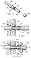
- Fig. 6 is an enlarged view of the cutting means such as the die 107 and punch 108 in Fig. 4.
- the die 107 is formed in a circular shape.
- the punch 108 is movable into an inner diameter portion 107a of the die 107.
- the inner diameter portion 107a is constituted by a horizontal narrow segment with a uniform inner diameter. This portion is successive to a front vertical plane 107b and a rear tapered plane 107c.
- the edge at the front end of the inner diameter portion 107a serves as a shearing blade.
- the outer periphery of the die is stepped and the stepped portion is engaged with an outer front half frame 117a so that it is not movable forward.
- the main part of the cutting device inclusive of the punch 108 and die 107 moves backward along a guide rail 119 by the function of the servo motor and ball screw shaft (not shown) so that the shielded wire 105 is extracted from the die 107.
- the braid opening pallets 110 are operated several times in its empty state, owing to its vibration, the refuse of the braid is thrown into a waste box.
Landscapes
- Engineering & Computer Science (AREA)
- Manufacturing & Machinery (AREA)
- Removal Of Insulation Or Armoring From Wires Or Cables (AREA)
- Processing Of Terminals (AREA)
Claims (5)
- Geflechtschneidevorrichtung für einen abgeschirmten Draht, aufweisend:gekennzeichnet durcheine Matrize (107), welche außerhalb des bloßgelegten Geflechts (22) des abgeschirmten Drahtes (15) angeordnet ist,Mittel (125) zum Öffnen des Geflechts (22),einen Stempel (108), der in das Innere des Geflechts (22) vorrückbar ist, wobei der Stempel (108) ein Ende hat, das als Scherblatt fungiert,
ein Führungselement (109), welches das Ende des Stempels (108) abdeckt, zum Führen des Geflechts (22) in eine Richtung, um es weiter zu öffnen, und zum Führen einer inneren Ummantelung (24) von dem abgeschirmten Draht (15) im Innern des Geflechts (22) zum Innern des Stempels (108), wobei das Führungselement (109) nach außen geöffnet und nach hinten bewegt wird, um es von dem Stempel (108) außer Eingriff zu bringen, wenn der Stempel (108) zum Schneiden des Geflechts (22) ins Innere des Geflechts (22) vorrückt. - Geflechtschneidevorrichtung gemäß Anspruch 1, wobei das Öffnungsmittel (125) aufweist:ein Paar Öffnungsbacken (110), die für ein freies Öffnen und Schließen gestaltet sind,ein Paar Gleitelemente (126, 127) mit dem Paar Öffnungsbacken (110) daran fixiert,ein Verbindungsglied (128) zum Bewegen des Paars Gleitelemente (126, 127) in entgegengesetzte Richtungen undAntriebsmittel (113, 114) zum Schwingbewegen des Verbindungsgliedes (128).
- Geflechtschneidevorrichtung gemäß Anspruch 1 oder 2, wobei das Führungselement (109) zwei Segmente aufweist, welche voneinander trennbar sind, wobei, wenn der Stempel vorrückt, die zwei Segmente des Führungselementes (109) durch Antriebsmittel (123) und ein Bewegungsmittel (122, 124) nach außen geöffnet werden, um zurückzuweichen.
- Verfahren zum Schneiden eines Geflechts eines abgeschirmten Drahts unter Verwendung der Geflechtschneidevorrichtung aus Anspruch 1, mit folgenden Schritten:Öffnen eines bloßgelegten Geflechts (22) des abgeschirmten Drahtes (15),weiteres Öffnen des Geflechts (22) durch ein Führungselement (109) entlang einer äußeren Neigung des Führungselementes (109), während eine innere Ummantelung (24) des abgeschirmten Drahtes (15) im Inneren des Geflechts (22) in das Innere eines kreisförmigen Stempels (108) geführt wird, welcher durch das Führungselement (109) abgedeckt wird,nach außen hin Öffnen und nach hinten Bewegen des Führungselementes (109), um dieses vom Stempel (108) zu lösen, undAbscheren des Geflechts (22) in eine erforderliche Länge zwischen dem Stempel (108) und der außerhalb des Geflechts (22) angeordneten Matrize (107), während der Stempel (108) im Innern des Geflechts (122) vorgerückt wird.
- Verfahren zum Schneiden eines Geflechts eines abgeschirmten Drahts gemäß Anspruch 4, wobei das Führungselement (109) nach dem Öffnen des Geflechts (22) entlang einer äußeren Neigung des Führungselementes (109) durch Trennen der beiden Segmente des Führungselementes (109) von dem Stempel (108) gelöst wird, so dass das Geflecht (22) weiter nach außen ausgeweitet wird.
Applications Claiming Priority (2)
| Application Number | Priority Date | Filing Date | Title |
|---|---|---|---|
| JP2001058476 | 2001-03-02 | ||
| JP2001058476A JP3908915B2 (ja) | 2001-03-02 | 2001-03-02 | シールド電線の編組切断装置及び編組切断方法 |
Publications (3)
| Publication Number | Publication Date |
|---|---|
| EP1237236A2 EP1237236A2 (de) | 2002-09-04 |
| EP1237236A3 EP1237236A3 (de) | 2004-01-02 |
| EP1237236B1 true EP1237236B1 (de) | 2005-06-01 |
Family
ID=18918193
Family Applications (1)
| Application Number | Title | Priority Date | Filing Date |
|---|---|---|---|
| EP02004766A Expired - Lifetime EP1237236B1 (de) | 2001-03-02 | 2002-03-01 | Vorrichtung und Verfahren für das Schneiden des Geflechts von abgeschirmtem Draht |
Country Status (4)
| Country | Link |
|---|---|
| US (1) | US6659140B2 (de) |
| EP (1) | EP1237236B1 (de) |
| JP (1) | JP3908915B2 (de) |
| DE (1) | DE60204369T2 (de) |
Families Citing this family (21)
| Publication number | Priority date | Publication date | Assignee | Title |
|---|---|---|---|---|
| JP3790416B2 (ja) * | 2000-11-06 | 2006-06-28 | 矢崎総業株式会社 | シールド電線の加工方法と加工装置 |
| EP1515403B1 (de) * | 2003-09-10 | 2007-10-24 | komax Holding AG | Kabelbearbeitungseinrichtung |
| JP2005229770A (ja) * | 2004-02-16 | 2005-08-25 | Yazaki Corp | シールド電線の編組切断装置 |
| DE102005024683B4 (de) * | 2005-05-30 | 2011-02-03 | Rosenberger Hochfrequenztechnik Gmbh & Co. Kg | Verfahren zum Vorbereiten eines Kabelendes für die Montage eines Steckverbinders |
| US7632147B2 (en) * | 2008-03-04 | 2009-12-15 | Nexus, Incorporated | Shielded cable plug and jack assembly |
| JP5095491B2 (ja) | 2008-05-09 | 2012-12-12 | 矢崎総業株式会社 | スリーブ挿入装置 |
| JP5362270B2 (ja) * | 2008-07-03 | 2013-12-11 | 矢崎総業株式会社 | シールド電線、及び該シールド電線の編組端末処理方法、並びに、編組端末処理装置 |
| DE102012020798B3 (de) * | 2012-10-23 | 2014-04-10 | Rosenberger Hochfrequenztechnik Gmbh & Co. Kg | Vorrichtung und Verfahren zum Bearbeiten eines Endes eines Kabels |
| DE202013002575U1 (de) | 2013-03-15 | 2013-04-17 | Rosenberger Hochfrequenztechnik Gmbh & Co. Kg | Steckverbinder |
| DE102015009989A1 (de) | 2015-07-31 | 2017-02-02 | Komax SLE GmbH & Co. KG | Kabelklemmvorrichtung zur Aufweitung für Schirmgeflechten von Kabeln |
| CN107196175B (zh) * | 2017-07-07 | 2023-07-07 | 深圳市日研精密机械有限公司 | 一种单头打端子单头插胶壳机以及线材插胶壳的方法 |
| DE102018117132B4 (de) * | 2018-07-16 | 2024-05-02 | Metzner Maschinenbau Gmbh | Vorrichtung und Verfahren zum Bearbeiten eines Endes eines elektrischen Kabels |
| CN108963720A (zh) * | 2018-07-17 | 2018-12-07 | 吉林省中赢高科技有限公司 | 一种线缆屏蔽网翻转装置 |
| US11018483B2 (en) * | 2018-09-04 | 2021-05-25 | Te Connectivity Corporation | Cable preparation machine |
| US11056852B2 (en) | 2018-09-05 | 2021-07-06 | TE Connectivity Services Gmbh | Cable preparation machine |
| CN109500913A (zh) * | 2019-01-09 | 2019-03-22 | 深圳市沃尔新能源电气科技股份有限公司 | 线缆屏蔽的裁剪装置 |
| DE102019130308A1 (de) | 2019-03-29 | 2020-10-01 | Metzner Holding GmbH | Vorrichtung und Verfahren zur Montage eines elektrischen Steckverbinders |
| JP7157100B2 (ja) * | 2020-06-05 | 2022-10-19 | 矢崎総業株式会社 | 編組折返し切断装置及び編組折返し切断方法 |
| CN114336224B (zh) * | 2020-09-30 | 2025-12-30 | 泰科电子(上海)有限公司 | 同轴线缆加工装置及加工同轴线缆的方法 |
| US12438347B2 (en) * | 2021-11-29 | 2025-10-07 | Aptiv Technologies AG | Method of cutting shielding conductor of a high voltage cable and apparatus to be used therefore |
| US20250385496A1 (en) * | 2024-06-17 | 2025-12-18 | Te Connectivity Solutions Gmbh | Method for Cable Braid Folding |
Family Cites Families (5)
| Publication number | Priority date | Publication date | Assignee | Title |
|---|---|---|---|---|
| US4719697A (en) * | 1985-08-05 | 1988-01-19 | Amp Incorporated | Method of preparing coaxial cable for termination |
| US4763410A (en) * | 1987-07-20 | 1988-08-16 | Amp Incorporated | Method for braided coaxial cable preparation |
| DE4027904C2 (de) * | 1990-09-03 | 1994-04-14 | Siemens Ag | Vorrichtung zur Bearbeitung von abgeschirmten elektrischen Leitungen |
| US6243947B1 (en) * | 1998-09-22 | 2001-06-12 | Sumitomo Wiring Systems, Ltd. | Method for processing an end of a shielded cable |
| US6363604B1 (en) * | 1999-05-21 | 2002-04-02 | Autonetworks Technologies, Ltd. | Method and apparatus for cutting braided sheath of shielding wire |
-
2001
- 2001-03-02 JP JP2001058476A patent/JP3908915B2/ja not_active Expired - Fee Related
-
2002
- 2002-02-27 US US10/083,603 patent/US6659140B2/en not_active Expired - Lifetime
- 2002-03-01 DE DE60204369T patent/DE60204369T2/de not_active Expired - Lifetime
- 2002-03-01 EP EP02004766A patent/EP1237236B1/de not_active Expired - Lifetime
Also Published As
| Publication number | Publication date |
|---|---|
| EP1237236A3 (de) | 2004-01-02 |
| DE60204369T2 (de) | 2006-03-16 |
| DE60204369D1 (de) | 2005-07-07 |
| JP2002262427A (ja) | 2002-09-13 |
| US20020121159A1 (en) | 2002-09-05 |
| US6659140B2 (en) | 2003-12-09 |
| EP1237236A2 (de) | 2002-09-04 |
| JP3908915B2 (ja) | 2007-04-25 |
Similar Documents
| Publication | Publication Date | Title |
|---|---|---|
| EP1237236B1 (de) | Vorrichtung und Verfahren für das Schneiden des Geflechts von abgeschirmtem Draht | |
| JP3803013B2 (ja) | シールド電線加工装置及びシールド電線加工方法 | |
| EP2871737B1 (de) | Abisoliervorrichtung und -Verfahren | |
| DE69926701T2 (de) | Verarbeitungsverfahren und -apparat eines Kabelendes | |
| KR100225316B1 (ko) | 와이어압착소켓 커넥터 제조 방법 및 장치 | |
| US7607217B2 (en) | Device for processing a wire | |
| US6776196B2 (en) | Braid folding unit and a braid folding method of a shielded wire | |
| US6363604B1 (en) | Method and apparatus for cutting braided sheath of shielding wire | |
| JP3117114B2 (ja) | 圧接ハーネス製造装置及び圧接ハーネス製造方法 | |
| DE69009368T2 (de) | Vorrichtung und Verfahren zur Drahtbearbeitung. | |
| EP1079478B1 (de) | Verfahren zum Abtrennen und/oder Entfernen der Isolierung von Kabeln, sowie eine Vorrichtung zur Durchführung dieses Verfahrens | |
| EP3713023A1 (de) | Abisoliervorrichtung sowie verfahren | |
| DE2928704A1 (de) | Vorrichtung zum gleichzeitigen anschluss einer reihe von kabeln an entsprechende kontakte | |
| JPH0817107B2 (ja) | 自動圧接機におけるシールドリボンケーブルの切断処理方法及びその装置 | |
| US5085114A (en) | Method for facilitating removal of insulation from wires | |
| US6442833B1 (en) | Method of stripping electric wire | |
| JP2002142325A (ja) | シールド電線の加工方法と加工装置 | |
| JP2001045623A (ja) | シールド電線の編組シールド切断方法及び切断装置 | |
| US3431621A (en) | Apparatus for connecting corresponding wires of pairs of wires to each other | |
| DE68923071T2 (de) | Leiterentmantelung und -abschluss in Multiaderkabeln. | |
| US3555672A (en) | High speed semiautomatic termination of coaxial cable | |
| US6289573B1 (en) | Apparatus for making up a cable | |
| CN116565662A (zh) | 一种带端子电线的制造方法 | |
| EP0989637A1 (de) | Einrichtung zur Konfektionierung eines Kabels | |
| EP0994539B1 (de) | Einrichtung zur Konfektionierung eines Kabels |
Legal Events
| Date | Code | Title | Description |
|---|---|---|---|
| PUAI | Public reference made under article 153(3) epc to a published international application that has entered the european phase |
Free format text: ORIGINAL CODE: 0009012 |
|
| AK | Designated contracting states |
Kind code of ref document: A2 Designated state(s): AT BE CH CY DE DK ES FI FR GB GR IE IT LI LU MC NL PT SE TR |
|
| AX | Request for extension of the european patent |
Free format text: AL;LT;LV;MK;RO;SI |
|
| PUAL | Search report despatched |
Free format text: ORIGINAL CODE: 0009013 |
|
| AK | Designated contracting states |
Kind code of ref document: A3 Designated state(s): AT BE CH CY DE DK ES FI FR GB GR IE IT LI LU MC NL PT SE TR |
|
| AX | Request for extension of the european patent |
Extension state: AL LT LV MK RO SI |
|
| RIC1 | Information provided on ipc code assigned before grant |
Ipc: 7H 02G 1/12 A |
|
| 17P | Request for examination filed |
Effective date: 20040227 |
|
| 17Q | First examination report despatched |
Effective date: 20040513 |
|
| AKX | Designation fees paid |
Designated state(s): CH DE FR LI |
|
| RIC1 | Information provided on ipc code assigned before grant |
Ipc: 7H 01R 43/28 B Ipc: 7H 02G 1/12 A |
|
| RIC1 | Information provided on ipc code assigned before grant |
Ipc: 7H 02G 1/12 A Ipc: 7H 01R 43/28 B |
|
| RIC1 | Information provided on ipc code assigned before grant |
Ipc: 7H 01R 43/28 B Ipc: 7H 02G 1/12 A |
|
| RIN1 | Information on inventor provided before grant (corrected) |
Inventor name: YAMAKAWA, NOBUAKI,C/O YAZAKI PARTS CO., LTD. |
|
| GRAP | Despatch of communication of intention to grant a patent |
Free format text: ORIGINAL CODE: EPIDOSNIGR1 |
|
| GRAS | Grant fee paid |
Free format text: ORIGINAL CODE: EPIDOSNIGR3 |
|
| GRAA | (expected) grant |
Free format text: ORIGINAL CODE: 0009210 |
|
| AK | Designated contracting states |
Kind code of ref document: B1 Designated state(s): CH DE FR LI |
|
| REG | Reference to a national code |
Ref country code: CH Ref legal event code: EP |
|
| REF | Corresponds to: |
Ref document number: 60204369 Country of ref document: DE Date of ref document: 20050707 Kind code of ref document: P |
|
| REG | Reference to a national code |
Ref country code: CH Ref legal event code: NV Representative=s name: PATENTANWAELTE SCHAAD, BALASS, MENZL & PARTNER AG |
|
| PLBE | No opposition filed within time limit |
Free format text: ORIGINAL CODE: 0009261 |
|
| STAA | Information on the status of an ep patent application or granted ep patent |
Free format text: STATUS: NO OPPOSITION FILED WITHIN TIME LIMIT |
|
| ET | Fr: translation filed | ||
| 26N | No opposition filed |
Effective date: 20060302 |
|
| REG | Reference to a national code |
Ref country code: FR Ref legal event code: PLFP Year of fee payment: 15 |
|
| REG | Reference to a national code |
Ref country code: FR Ref legal event code: PLFP Year of fee payment: 16 |
|
| REG | Reference to a national code |
Ref country code: FR Ref legal event code: PLFP Year of fee payment: 17 |
|
| PGFP | Annual fee paid to national office [announced via postgrant information from national office to epo] |
Ref country code: DE Payment date: 20200218 Year of fee payment: 19 |
|
| PGFP | Annual fee paid to national office [announced via postgrant information from national office to epo] |
Ref country code: CH Payment date: 20200313 Year of fee payment: 19 |
|
| PGFP | Annual fee paid to national office [announced via postgrant information from national office to epo] |
Ref country code: FR Payment date: 20200214 Year of fee payment: 19 |
|
| REG | Reference to a national code |
Ref country code: DE Ref legal event code: R119 Ref document number: 60204369 Country of ref document: DE |
|
| REG | Reference to a national code |
Ref country code: CH Ref legal event code: PL |
|
| PG25 | Lapsed in a contracting state [announced via postgrant information from national office to epo] |
Ref country code: CH Free format text: LAPSE BECAUSE OF NON-PAYMENT OF DUE FEES Effective date: 20210331 Ref country code: LI Free format text: LAPSE BECAUSE OF NON-PAYMENT OF DUE FEES Effective date: 20210331 Ref country code: FR Free format text: LAPSE BECAUSE OF NON-PAYMENT OF DUE FEES Effective date: 20210331 Ref country code: DE Free format text: LAPSE BECAUSE OF NON-PAYMENT OF DUE FEES Effective date: 20211001 |