EP1237236B1 - Apparatus and method for cutting braid of shielded wire - Google Patents
Apparatus and method for cutting braid of shielded wire Download PDFInfo
- Publication number
- EP1237236B1 EP1237236B1 EP02004766A EP02004766A EP1237236B1 EP 1237236 B1 EP1237236 B1 EP 1237236B1 EP 02004766 A EP02004766 A EP 02004766A EP 02004766 A EP02004766 A EP 02004766A EP 1237236 B1 EP1237236 B1 EP 1237236B1
- Authority
- EP
- European Patent Office
- Prior art keywords
- braid
- punch
- guide member
- shielded wire
- opening
- Prior art date
- Legal status (The legal status is an assumption and is not a legal conclusion. Google has not performed a legal analysis and makes no representation as to the accuracy of the status listed.)
- Expired - Lifetime
Links
- 238000005520 cutting process Methods 0.000 title claims description 31
- 238000000034 method Methods 0.000 title claims description 9
- 238000010008 shearing Methods 0.000 claims description 5
- 239000002184 metal Substances 0.000 description 5
- 238000003754 machining Methods 0.000 description 3
- 230000001154 acute effect Effects 0.000 description 2
- 239000004020 conductor Substances 0.000 description 1
- 238000002788 crimping Methods 0.000 description 1
- 238000003780 insertion Methods 0.000 description 1
- 230000037431 insertion Effects 0.000 description 1
- 230000001788 irregular Effects 0.000 description 1
- 238000004519 manufacturing process Methods 0.000 description 1
- 238000003672 processing method Methods 0.000 description 1
- 238000004080 punching Methods 0.000 description 1
- 239000011347 resin Substances 0.000 description 1
- 229920005989 resin Polymers 0.000 description 1
- 230000007306 turnover Effects 0.000 description 1
- 239000002699 waste material Substances 0.000 description 1
Images


Classifications
-
- H—ELECTRICITY
- H01—ELECTRIC ELEMENTS
- H01R—ELECTRICALLY-CONDUCTIVE CONNECTIONS; STRUCTURAL ASSOCIATIONS OF A PLURALITY OF MUTUALLY-INSULATED ELECTRICAL CONNECTING ELEMENTS; COUPLING DEVICES; CURRENT COLLECTORS
- H01R43/00—Apparatus or processes specially adapted for manufacturing, assembling, maintaining, or repairing of line connectors or current collectors or for joining electric conductors
- H01R43/28—Apparatus or processes specially adapted for manufacturing, assembling, maintaining, or repairing of line connectors or current collectors or for joining electric conductors for wire processing before connecting to contact members, not provided for in groups H01R43/02 - H01R43/26
-
- H—ELECTRICITY
- H01—ELECTRIC ELEMENTS
- H01R—ELECTRICALLY-CONDUCTIVE CONNECTIONS; STRUCTURAL ASSOCIATIONS OF A PLURALITY OF MUTUALLY-INSULATED ELECTRICAL CONNECTING ELEMENTS; COUPLING DEVICES; CURRENT COLLECTORS
- H01R9/00—Structural associations of a plurality of mutually-insulated electrical connecting elements, e.g. terminal strips or terminal blocks; Terminals or binding posts mounted upon a base or in a case; Bases therefor
- H01R9/03—Connectors arranged to contact a plurality of the conductors of a multiconductor cable, e.g. tapping connections
- H01R9/05—Connectors arranged to contact a plurality of the conductors of a multiconductor cable, e.g. tapping connections for coaxial cables
-
- Y—GENERAL TAGGING OF NEW TECHNOLOGICAL DEVELOPMENTS; GENERAL TAGGING OF CROSS-SECTIONAL TECHNOLOGIES SPANNING OVER SEVERAL SECTIONS OF THE IPC; TECHNICAL SUBJECTS COVERED BY FORMER USPC CROSS-REFERENCE ART COLLECTIONS [XRACs] AND DIGESTS
- Y10—TECHNICAL SUBJECTS COVERED BY FORMER USPC
- Y10T—TECHNICAL SUBJECTS COVERED BY FORMER US CLASSIFICATION
- Y10T29/00—Metal working
- Y10T29/49—Method of mechanical manufacture
- Y10T29/49002—Electrical device making
- Y10T29/49117—Conductor or circuit manufacturing
- Y10T29/49123—Co-axial cable
Definitions
- the sheath of the tip of a shielded wire cut into segments of a prescribed length is stripped using a tabletop tool so that the braid of conductive metal is exposed.
- the braid is cut into segments each having a prescribed length.
- the braid is folded back toward the contact using a center punching.
- the shield pipe is squeezed using a squeezing machine.
- the inner face at the tip of the shielded wire is stripped using the tabletop tool so that a terminal is connected to a core wire by a crimping machine (The shape and other details of the shield contact and shield pipe can be seen from Fig. 3).
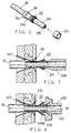
- Fig. 6 is an enlarged view of the cutting means such as the die 107 and punch 108 in Fig. 4.
- the die 107 is formed in a circular shape.
- the punch 108 is movable into an inner diameter portion 107a of the die 107.
- the inner diameter portion 107a is constituted by a horizontal narrow segment with a uniform inner diameter. This portion is successive to a front vertical plane 107b and a rear tapered plane 107c.
- the edge at the front end of the inner diameter portion 107a serves as a shearing blade.
- the outer periphery of the die is stepped and the stepped portion is engaged with an outer front half frame 117a so that it is not movable forward.
- the main part of the cutting device inclusive of the punch 108 and die 107 moves backward along a guide rail 119 by the function of the servo motor and ball screw shaft (not shown) so that the shielded wire 105 is extracted from the die 107.
- the braid opening pallets 110 are operated several times in its empty state, owing to its vibration, the refuse of the braid is thrown into a waste box.
Landscapes
- Engineering & Computer Science (AREA)
- Manufacturing & Machinery (AREA)
- Removal Of Insulation Or Armoring From Wires Or Cables (AREA)
- Processing Of Terminals (AREA)
Description
- This invention relates to an apparatus and method for effectively automatically cutting a braid of a shielded wire having a relatively large diameter for use in an electric vehicle and others.
- Traditionally, a shielded wire was processed manually in all the steps.
- Specifically, the sheath of the tip of a shielded wire cut into segments of a prescribed length is stripped using a tabletop tool so that the braid of conductive metal is exposed. The braid is cut into segments each having a prescribed length. With a shield contact of conductive metal manually inserted into the shielded wire, the braid is folded back toward the contact using a center punching. With a shield pipe of conductive metal manually inserted in the shielded wire and braid sandwiched between and kept in contact with the shield contact and the shield pipe, the shield pipe is squeezed using a squeezing machine. Further, the inner face at the tip of the shielded wire is stripped using the tabletop tool so that a terminal is connected to a core wire by a crimping machine (The shape and other details of the shield contact and shield pipe can be seen from Fig. 3).
- The shielded wire is used in such a mode that a connecting flange is combined with the shield pipe and earth-connected to a vehicle body along the outer surface of the housing of resin. The terminal of the shielded wire is connected to a motor, inverter or battery of an electric vehicle.
- EP 1 054 494 discloses a braid cutting apparatus according to the preamble of claim 1.
- However, in the above conventional means for cutting the braid of the shielded wire, the braid was manually cut using snips. Therefore, the length of each of the segments of the cut braid is uneven. The tip of cut braid is liable to be irregular. The quality is not stable, and a large number of man-hours is required. This presents a problem of increasing the production cost.
- In view of the above problem, a first object of this invention is to provide an apparatus according to claim 1, which can cut the braid of a shielded wire into precise lengths cleanly with no irregularity and effectively with a small number of man-hours.
- A second object of this invention is to provide a method according to
claim 4 for cutting the braid of a shielded wire into precise lengths cleanly with no irregularity and effectively with a small number of man-hours. - In order to attain the above first object, in accordance with this invention, there is provided a braid cutting apparatus for a shielded wire described in claim 1 is comprising: a die located outside an exposed braid of the shielded wire; means for opening the braid; a punch which is to advance inside the braid; and a guide member for guiding the braid in a direction to open further and an inner shin of the shielded wire inside the braid to an inside of the punch.
- In this configuration, the exposed braid of the shielded wire is inserted into the inside of die, the braid is opened outwardly in taper by a braid opening means, the inner sheath of the shielded wire is inserted in the inside of the punch, and the braid is further opened in taper outwardly by a guide member. For this reason, the tip of the punch is inserted surely and smoothly inside the braid, i.e. between the braid and the inner sheath of the shielded wire so that the braid can be surely sheared between the punch and the die.
- In the above apparatus, preferably, the opening means comprises: a pair of opening pallets which are freely reclosable, a pair of sliding members with the pair of opening pallets fixed; a link for moving the pair of sliding members in opposite directions; and driving means for swinging the link.
- In this configuration, the link is swung by the driving means so that the pair of sliders are opened or closed simultaneously with the opening pallets. Therefore, the braid of the shielded wire is pressed repeatedly by the opening pallets under appropriate force. Accordingly, the braid can be surely opened in a trumpet without being injured.
- In the apparatus described above, preferably, the guide member is made dividable, and when the punch advances, the guide member is opened outwardly by the driving means and a moving means to retreat.
- In this configuration, since the guide member opens and retreats, when it is opens, the braid is opened further outwardly. For this reason, the punch is inserted more surely inside the braid.
- In order to attain the second object, there is provided a method of cutting a braid of a shielded wire comprising the steps of: opening an exposed braid of the shielded wire, further opening the braid along an outer slope of a guide member while guiding an inner sheath of the shielded wire inside the braid to an inside of a circular punch, and shearing the braid into a required length between the punch and a die located outside the braid while advancing the punch inside the braid.
- In this configuration, the braid opened primarily opened by the opening means is guided along the outer slope of the guide member so that it is further (secondarily) opened greatly outwardly. The inner sheath of the shielded wire is smoothly inserted into the guide member, i.e. inside the punch along the inner slope of the guide member.
- In the method described above, preferably, after the braid is opened along an outer slope of the guide member, the guide member is opened outwardly.
- In this configuration, since the braid is opened further outwardly when the guide member is opened, the punch is inserted more surely inside the braid. Thus, the tip of the punch and that of the braid do not interfere with each other so that the braid does not bend inwardly. This prevents poor cutting of the braid.
- The above and other objects and features of this invention will be more apparent from the following description taken in conjunction with the accompanying drawings.
-
- Fig. 1 is a schematic perspective view of an embodiment of a shielded wire machining device inclusive of a braid cutting device of a shielded wire according to this invention;
- Figs. 2A to 2J are plan views showing the machining method of the shielded wire;
- Fig. 3 is an exploded perspective view showing the state on the way of machining the shielded wire;
- Fig. 4 is a side view of an embodiment of the braid cutting device for a shielded wire according to this invention;
- Fig. 5 is a front view showing the braid turn-over means of the braid cutting device;
- Fig. 6 is a sectional view of the main part of the braid cutting means in Fig. 8;
- Fig. 7 is a view for explaining the state of cutting the braid; and
- Fig. 8 is a view showing the function of a guide member.
-
- Now referring to the drawings, an explanation will be given of an embodiment of this invention.
- Fig. 1 schematically shows an embodiment of a shielded wire processing device including a device for cutting the braid of a shielded wire according to this invention.
- A shielded wire processing apparatus, generally 1 includes individual devices arranged successively from the right side, i.e., an
operation console 2 for performing a change in a product number, switching between a manual operation and an automatic operation, etc., awire setting device 3, a shieldcontact fitting device 4, asheath incision device 5, asheath extracting device 6, abraid cutting device 7, a braid fold-back device 8, shield pipe inserting device 9 (8 and 9 are illustrated as a single device for brevity of illustration) , sheath pipe squeezing device 10, a peeling device 11, aterminal squeezing device 12, aproduct drawing device 13, and aconveying device 14 for moving a shieldedwire 15 along therespective devices 3 to 13. Thesedevices 3 to 13 are arranged in parallel at substantially regular intervals. - In Fig. 1,
reference numeral 16 denotes a hopper for supplying a shield contact, andreference numeral 17 denotes a hopper for supplying a shield pipe. The shieldedwires 15 each may a thick wire having a sectional area of about 15 mm2. The shieldedwires 15 folded back in a U-shape or not folded back are set one by one in parallel in thewire setting device 3 at the right end of theconveying device 14. - Now referring to Figs. 1 and 2, an explanation will be given of a shielded wire processing method using the shielded wire processing device 1, and its operation.
- First, as seen from Fig. 2A, the shielded
wire 15 cut into a segment having a prescribed length is set in theshield setting device 3 by an operator. The only operation performed by the operator is to set the wire. When the shieldedwire 15 is set, thewire conveying device 14 is shifted by one pitch leftward to convey the shieldedwire 15 to the adjacent shieldcontact inserting device 4. - As seen from Fig. 2B, a ring-
shaped shield contact 19 of conductive metal is fit over the shieldedwire 15 by the shieldcontact fitting device 4. As also seen from Fig. 3, theshield contact 19 is composed of a large-diameter segment 19a and a small-diameter segment 19b which are stepped. The shieldedwire 15 inserted into theshield contact 19 is conveyed to thesheath incision device 5 by theconveyer device 14. As seen from Fig. 2C, acircular incision 21 is made on the insulating sheath (outer sheath) 20 of the shieldedwire 15 at a prescribed position located nearer to the tip of the wire than theshield contact 19. - The shielded
wire 15 is conveyed to thesheath drawing device 6. As seen from Fig. 2D, thesheath 20 is drawn out so that an internalmetallic braid 22 is exposed over a prescribed length. It is needless to say that thebraid 22 is composed of slender metallic wires which are knitted in a crossing manner as seen from Fig. 3. The shielded wire is conveyed to thebraid cutting device 7. As seen from Fig. 2E, the exposedbraid 22 is cut into a prescribed length so that an insulatinginner sheath 24 is exposed. - The shielded
wire 15 is conveyed to the braid fold-back device 8. As seen from Fig. 2F, thebraid 22 is folded back toward the small-diameter portion 19b of theshield contact 19. Further, a ring-shapedshield pipe 23 of conductive metal is inserted the from the tip side of the shieldedwire 15 so that the braid 22 (not shown) is sandwiched between and brought in contact with the outer surface of thesmall diameter portion 19b of theshield contact 19 and the inner surface of theshield pipe 23. The angle of fold-back of thebraid 22 ranges from 90° to 180°. - The shielded
wire 15 is conveyed to the shield pipe squeezing device 10. As seen from Fig. 2H, theshield pipe 23 is squeezed in a hexagon so that it is fixed to theshield contact 19. Since thebraid 23 is sandwiched between theshield contact 19 and theshield pipe 23, theshield contact 19 and theshield pipe 23 are firmly fixed to the shieldedwire 15. - The shielded
wire 15 is conveyed to the peeling device 11. As seen from Fig. 21, the tip side of theinner sheath 24 is peeled over a prescribed length so that a core (conductor) is exposed. Further, the shieldedwire 15 is conveyed to theterminal squeezing device 12. As seen from Fig. 2J, a terminal 26 is crimped on the exposedcore 25. Finally, theproduct 27 of the shielded wire is taken from the shielded wire processing device 1 into an external pallet (not shown) with the aid of theproduct drawing device 13. - Incidentally, the
terminal squeezing device 12 may be provided separately from the shielded wire processing device 1. - Now referring to Figs. 4 to 8, an explanation will be given of an embodiment of a device for cutting the braid of a shielded wire and the braid cutting method according to this invention.
- In Fig. 4,
reference numeral 107 denotes a ring-shaped die for cutting a braid; 109 a ring-shaped guide member; 110 a ring-shaped braid opening pallet; 111 an air-actuated or hydraulic horizontal cylinder for primarily advancing apunch 108; and 112 a large-sized and strong air-actuated or hydraulic cylinder for secondarily advancing thepunch 108 and cutting thebraid 22 of the shieldedwire 15 between the die 107 and thepunch 108.Reference numerals 113 and 114 (Fig. 5) denote air cylinders (driving means) for laterally opening/closing the ring-shapedbraid opening pallet 110, respectively. - The shielded
wire 15 is caught by achuck 115 in its intermediate portion in the longitudinal direction. The shieldedwire 15 is also supported by a supporting chuck (supporting member) 116 in its tip side so that it is movable in the longitudinal direction. Thechuck 115 includes a pair of left and right catching pallets. Thechuck 115 is opened/closed by theair chuck cylinder 105. The wire chuck in the conveyer device 4 (Fig. 1) has the same structure. - The supporting
chuck 116 includes a pair of left and right symmetrical closable pallets which do not catch the shieldedwire 15, but horizontally supports it in light contact therewith. Thedie 107 is located ahead of the supportingchuck 116. Aframe 117 to which thedie 107 is fixed and the supportingchuck 116 are integrally fixed to ahorizontal base plate 118. Thebase plate 118 is adapted to be slidable in the longitudinal direction of the wire along aguide rail 119. - The
base plate 118 is driven back and forth by a ball screw shaft (not shown) . Aprimary cylinder 111 with a small diameter for moving a punch is attached to theframe 120 extended upright at the rear of thebase plate 118. Asecondary cylinder 112 with a large diameter is adapted to be movable back and forth relative to aframe 120 by a guiding means 121 such as a guide rail. A horizontal air cylinder (moving means) 122 with a small diameter for moving the guide member back and forth is attached to thesecondary cylinder 112. Theguide member 109 in a chuck-system is coupled with an opening/closing cylinder 123 which is in turn coupled with arod 124 of the movingcylinder 122. - As seen from Fig. 5, a braid opening means 125 has a pair of left and right
braid opening pallets 110 which are attached to sliding plates (sliding member) 126 and 127 which are movable in opposite directions. Each of the slidingplates vertical link 128 at upper and lower shaft positions. The upper end and lower end of thelink 128 are coupled with therods cylinders cylinders plates - Fig. 6 is an enlarged view of the cutting means such as the
die 107 and punch 108 in Fig. 4. Thedie 107 is formed in a circular shape. Thepunch 108 is movable into aninner diameter portion 107a of thedie 107. Theinner diameter portion 107a is constituted by a horizontal narrow segment with a uniform inner diameter. This portion is successive to a frontvertical plane 107b and a reartapered plane 107c. The edge at the front end of theinner diameter portion 107a serves as a shearing blade. The outer periphery of the die is stepped and the stepped portion is engaged with an outerfront half frame 117a so that it is not movable forward. - The
braid opening pallets 110 are kept in intimate contact with the front end of the die 107 so as to be slidable in the radial direction. Arear half frame 117b is kept in contact with the rear end of thedie 107. The taperedplane 107c is smoothly successive to the taperedplane 117c. Each of the taperedplanes braid 22 of the shielded wire (Fig. 4). - The
punch 108 is cylindrically shaped, and composed of a thin segment 108a with a small diameter on the tip side and athick segment 108b with a large diameter backward successive thereto. The inner diameter of the thin segment 108a is equal to that of thethick segment 108b. The outer diameter of the thin segment 108a is smaller than that of thethick segment 108b. Theouter edge 108c at the tip of the thin segment 108a serves as a shearing blade. - The thin segment 108a advances into the inner diameter portion 109c of the
guide member 109 with a slight gap therefrom. Theguide member 109 is formed in a circular shape divided into two left and right segments. Theguide member 109 has aninner slope 109a for wire guiding, which covers the tip of the thin segment 108a of thepunch 108, and anouter slope 109b for braid guiding. - The
inner slope 109a is formed is a short length whereas theouter slope 109b is formed in a relatively long length extended backward. Theinner slope 109a is successive to a circularvertical plane 109d with which the tip of the thin segment 108a of thepunch 108 is in contact. The minimum inner diameter of theguide member 109 is equal to the inner diameter of the thin segment 108a of thepunch 108. Bothslopes guide member 109 is formed in a wedge shape in section. Theguide member 109 is provided integrally to or separately from a pair of left andright arms 104 which can be opened/closed freely. Specifically, the onesemi-circular guide member 109 and the othersemi-circular guide member 109 are attached to the onearm 104 and theother arm 104, respectively. - The pair of left and
right guide members 109 are opened/closed by an opening/closing cylinder 123 (Fig. 4). In opening the guide members, thepunch 108 advances toward thedie 107. Thebraid opening pallet 110 has a slightly acute circular tip, whose degree is less than a cutter. In the description of the specification, the "front" of the shieldedwire 15 is coincident to the "front" of thedie 107. In contrast, the "front" of thepunch 108 is opposite to the "front" of theguide member 109. - In Fig. 4, the
horizontal base plate 118 is advanced slidably by a ball screwing shaft and servo motor so that the tip of the shielded wire 15 (exposed portion of the braid 22) is inserted into thedie 107. In this state, a pair of upper andlower cylinders link 128 swings so that thebraid opening pallets 110 repeatedly open/close integrally to the pair of left andright slide plates pallets 110 press thebraid 22 of the shieldedwire 15 against theinner sheath 24 several times (four to five times) so that thebraid 22 is gradually expanded in diameter outwardly. Accordingly, thecircular punch 108 can be inserted comparatively easily between thebraid 22 of thewire 15 andinner sheath 24. - In the state where the
braid 22 has been expanded, thesecondary cylinder 112, punch 108 and guidemember 109 are advanced by the operation of extending theprimary cylinder 111 as shown in Fig. 4. Then, as shown in Fig. 8, theinner sheath 24 of the shieldedwire 15 is initially (slightly) inserted into the inner diameter portion (inner space) of thepunch 108. Simultaneously, the opened portion of thebraid 22 slides along theouter slope 109b of theguide member 109 so that it is further opened. Since theguide member 109 is opened left and right, thebraid 22 is extended more outwardly. In this state, theguide member 109 is moved backward. - The operation of the
guide member 109 of opening the braid further facilitates the insertion of thepunch 108. When the shieldedwire 15 is inserted, the tip of thepunch 108 is completely housed in the inner diameter portion 109c of theguide member 109 so that interference between the tip of the inner sheath of the shieldedwire 15 and that of the tip of thepunch 108 is prevented. Thus, the wire can be smoothly inserted. - The
guide member 109 is opened outwardly, and moved backward by the compressing operation of thehorizontal air cylinder 122 as shown in Fig. 4 so that thesecondary cylinder 112 is extended. Then, thepunch 108 is inserted into the opened portion of thebraid 22 as shown in Fig. 7. At this time, thebraid 22 is sandwiched between the outer periphery of thepunch 108 and the inner periphery of thedie 7 and sheared or cut instantaneously. This is performed to exclude the redundant segment at the tip of thebraid 22 and define the protruding length of thebraid 22 of theouter sheath 20. - The main part of the cutting device inclusive of the
punch 108 and die 107 moves backward along aguide rail 119 by the function of the servo motor and ball screw shaft (not shown) so that the shieldedwire 105 is extracted from thedie 107. In this state, when thebraid opening pallets 110 are operated several times in its empty state, owing to its vibration, the refuse of the braid is thrown into a waste box. - By moving forward or backward the main part of the cutting device using the servo motor and ball screw shaft, the cutting length of the
braid 22 can be adjusted freely so as to correspond to the shieldedwires 15 of the several product numbers. In this case, thebraid 22 is turned over so that theinner sheath 24 is located on the inner wall of thepunch 108. In this state, thebraid 22 is cut by the outside of thepunch 108 so that only thebraid 22 can be surely cut without injuring theinner sheath 24 and thecore 25. - The shielded
wire 15 with thebraid 22 thus partially cut is sent to the adjacent braid fold-back device 8 by the conveying device 14 (Fig. 1).
Claims (5)
- A braid cutting apparatus for a shielded wire comprising:a die (107) located outside an exposed braid (22) of the shielded wire (15);means (125) for opening said braid (22);a punch (108) which is to advance inside said braid (22), wherein said punch (108) has a tip serving as a shearing blade; characterised by
a guide member (109), which covers the tip of said punch (108) for guiding the braid (22) in a direction to open further and for guiding an inner sheath (24) of said shielded wire (15) inside said braid (22) to an inside of said punch (108), wherein said guide member (109) is opened outwardly and moved backwards in order to disengage from said punch (108) when advancing the punch (108) inside said braid (22) for cutting the braid (22). - A braid cutting apparatus according to claim 1, wherein said opening means (125) comprises:a pair of opening pallets (110) which are formed to be freely opened and closed,a pair of sliding members (126, 127) with said pair of opening pallets (110) fixed;a link (128) for moving said pair of sliding members (126, 127) in opposite directions; anddriving means (113, 114) for swinging said link (128).
- A braid cutting apparatus according to claim 1 or 2, wherein said guide member (109) comprises two segments which are dividable from each other, and when said punch advances, said two segments of the guide member (109) are opened outwardly by driving means (123) and a moving means (122, 124) to retreat.
- A method of cutting a braid of a shielded wire using the braid cutting apparatus of claim 1, comprising the steps of:opening an exposed braid (22) of the shielded wire (15),further opening said braid (22) by a guide member (109) along an outer slope of said guide member (109) while guiding an inner sheath (24) of said shielded wire (15) inside said braid (22) to an inside of a circular punch (108) covered by said guide member (109),opening outwardly and moving backwards of said guide member (109) in order to disengage from said punch (108), andshearing said braid (22) into a required length between said punch (108) and a die (107) located outside said braid (22) while advancing said punch (108) inside said braid (22).
- A method of cutting a braid of a shielded wire according to claim 4, wherein after said braid (22) is opened along an outer slope of said guide member (109), said guide member (109) disengaging from the punch (108) by dividing two segments of said guide member (109) so that the braid (22) is extended more outwardly.
Applications Claiming Priority (2)
| Application Number | Priority Date | Filing Date | Title |
|---|---|---|---|
| JP2001058476 | 2001-03-02 | ||
| JP2001058476A JP3908915B2 (en) | 2001-03-02 | 2001-03-02 | Braided cutting device for shielded wire and braided cutting method |
Publications (3)
| Publication Number | Publication Date |
|---|---|
| EP1237236A2 EP1237236A2 (en) | 2002-09-04 |
| EP1237236A3 EP1237236A3 (en) | 2004-01-02 |
| EP1237236B1 true EP1237236B1 (en) | 2005-06-01 |
Family
ID=18918193
Family Applications (1)
| Application Number | Title | Priority Date | Filing Date |
|---|---|---|---|
| EP02004766A Expired - Lifetime EP1237236B1 (en) | 2001-03-02 | 2002-03-01 | Apparatus and method for cutting braid of shielded wire |
Country Status (4)
| Country | Link |
|---|---|
| US (1) | US6659140B2 (en) |
| EP (1) | EP1237236B1 (en) |
| JP (1) | JP3908915B2 (en) |
| DE (1) | DE60204369T2 (en) |
Families Citing this family (21)
| Publication number | Priority date | Publication date | Assignee | Title |
|---|---|---|---|---|
| JP3790416B2 (en) * | 2000-11-06 | 2006-06-28 | 矢崎総業株式会社 | Shielding wire processing method and processing equipment |
| EP1515403B1 (en) * | 2003-09-10 | 2007-10-24 | komax Holding AG | Cable processing apparatus |
| JP2005229770A (en) * | 2004-02-16 | 2005-08-25 | Yazaki Corp | Braided cutting device for shielded wire |
| DE102005024683B4 (en) * | 2005-05-30 | 2011-02-03 | Rosenberger Hochfrequenztechnik Gmbh & Co. Kg | Method of preparing a cable end for mounting a connector |
| US7632147B2 (en) * | 2008-03-04 | 2009-12-15 | Nexus, Incorporated | Shielded cable plug and jack assembly |
| JP5095491B2 (en) | 2008-05-09 | 2012-12-12 | 矢崎総業株式会社 | Sleeve insertion device |
| JP5362270B2 (en) * | 2008-07-03 | 2013-12-11 | 矢崎総業株式会社 | Shielded wire, braided terminal processing method of shielded wire, and braided terminal processing apparatus |
| DE102012020798B3 (en) * | 2012-10-23 | 2014-04-10 | Rosenberger Hochfrequenztechnik Gmbh & Co. Kg | Apparatus and method for processing an end of a cable |
| DE202013002575U1 (en) | 2013-03-15 | 2013-04-17 | Rosenberger Hochfrequenztechnik Gmbh & Co. Kg | Connectors |
| DE102015009989A1 (en) | 2015-07-31 | 2017-02-02 | Komax SLE GmbH & Co. KG | Cable clamping device for widening screen braids of cables |
| CN107196175B (en) * | 2017-07-07 | 2023-07-07 | 深圳市日研精密机械有限公司 | Single-head terminal beating single-head rubber shell inserting machine and method for wire rubber shell inserting |
| DE102018117132B4 (en) * | 2018-07-16 | 2024-05-02 | Metzner Maschinenbau Gmbh | Apparatus and method for processing an end of an electrical cable |
| CN108963720A (en) * | 2018-07-17 | 2018-12-07 | 吉林省中赢高科技有限公司 | A kind of cable shielding net turnover device |
| US11018483B2 (en) * | 2018-09-04 | 2021-05-25 | Te Connectivity Corporation | Cable preparation machine |
| US11056852B2 (en) | 2018-09-05 | 2021-07-06 | TE Connectivity Services Gmbh | Cable preparation machine |
| CN109500913A (en) * | 2019-01-09 | 2019-03-22 | 深圳市沃尔新能源电气科技股份有限公司 | The Scissoring device of cable shielding |
| DE102019130308A1 (en) | 2019-03-29 | 2020-10-01 | Metzner Holding GmbH | Device and method for assembling an electrical connector |
| JP7157100B2 (en) * | 2020-06-05 | 2022-10-19 | 矢崎総業株式会社 | Braid cuff cutting device and braid cuff cutting method |
| CN114336224B (en) * | 2020-09-30 | 2025-12-30 | 泰科电子(上海)有限公司 | Coaxial cable processing equipment and methods for processing coaxial cables |
| US12438347B2 (en) * | 2021-11-29 | 2025-10-07 | Aptiv Technologies AG | Method of cutting shielding conductor of a high voltage cable and apparatus to be used therefore |
| US20250385496A1 (en) * | 2024-06-17 | 2025-12-18 | Te Connectivity Solutions Gmbh | Method for Cable Braid Folding |
Family Cites Families (5)
| Publication number | Priority date | Publication date | Assignee | Title |
|---|---|---|---|---|
| US4719697A (en) * | 1985-08-05 | 1988-01-19 | Amp Incorporated | Method of preparing coaxial cable for termination |
| US4763410A (en) * | 1987-07-20 | 1988-08-16 | Amp Incorporated | Method for braided coaxial cable preparation |
| DE4027904C2 (en) * | 1990-09-03 | 1994-04-14 | Siemens Ag | Device for processing shielded electrical cables |
| US6243947B1 (en) * | 1998-09-22 | 2001-06-12 | Sumitomo Wiring Systems, Ltd. | Method for processing an end of a shielded cable |
| US6363604B1 (en) * | 1999-05-21 | 2002-04-02 | Autonetworks Technologies, Ltd. | Method and apparatus for cutting braided sheath of shielding wire |
-
2001
- 2001-03-02 JP JP2001058476A patent/JP3908915B2/en not_active Expired - Fee Related
-
2002
- 2002-02-27 US US10/083,603 patent/US6659140B2/en not_active Expired - Lifetime
- 2002-03-01 DE DE60204369T patent/DE60204369T2/en not_active Expired - Lifetime
- 2002-03-01 EP EP02004766A patent/EP1237236B1/en not_active Expired - Lifetime
Also Published As
| Publication number | Publication date |
|---|---|
| EP1237236A3 (en) | 2004-01-02 |
| DE60204369T2 (en) | 2006-03-16 |
| DE60204369D1 (en) | 2005-07-07 |
| JP2002262427A (en) | 2002-09-13 |
| US20020121159A1 (en) | 2002-09-05 |
| US6659140B2 (en) | 2003-12-09 |
| EP1237236A2 (en) | 2002-09-04 |
| JP3908915B2 (en) | 2007-04-25 |
Similar Documents
| Publication | Publication Date | Title |
|---|---|---|
| EP1237236B1 (en) | Apparatus and method for cutting braid of shielded wire | |
| JP3803013B2 (en) | Shielded wire processing apparatus and shielded wire processing method | |
| EP2871737B1 (en) | Insulation stripping device and method | |
| DE69926701T2 (en) | Processing method and apparatus of a cable end | |
| KR100225316B1 (en) | Wire Crimp Socket Connector Manufacturing Method and Device | |
| US7607217B2 (en) | Device for processing a wire | |
| US6776196B2 (en) | Braid folding unit and a braid folding method of a shielded wire | |
| US6363604B1 (en) | Method and apparatus for cutting braided sheath of shielding wire | |
| JP3117114B2 (en) | Pressure welding harness manufacturing apparatus and pressure welding harness manufacturing method | |
| DE69009368T2 (en) | Device and method for wire processing. | |
| EP1079478B1 (en) | Method and device for cutting and/or removing insulation from insulated cables | |
| EP3713023A1 (en) | Stripping device and method | |
| DE2928704A1 (en) | DEVICE FOR SIMULTANEOUSLY CONNECTING A ROW OF CABLES TO RELATED CONTACTS | |
| JPH0817107B2 (en) | Method and device for cutting shielded ribbon cable in automatic crimping machine | |
| US5085114A (en) | Method for facilitating removal of insulation from wires | |
| US6442833B1 (en) | Method of stripping electric wire | |
| JP2002142325A (en) | Processing method and processing equipment for shielded wires | |
| JP2001045623A (en) | Method and apparatus for cutting braided shield of shielded electric wire | |
| US3431621A (en) | Apparatus for connecting corresponding wires of pairs of wires to each other | |
| DE68923071T2 (en) | Cable stripping and termination in multi-core cables. | |
| US3555672A (en) | High speed semiautomatic termination of coaxial cable | |
| US6289573B1 (en) | Apparatus for making up a cable | |
| CN116565662A (en) | Manufacturing method of electric wire with terminal | |
| EP0989637A1 (en) | Device for assembling a cable | |
| EP0994539B1 (en) | Device for assembling a cable |
Legal Events
| Date | Code | Title | Description |
|---|---|---|---|
| PUAI | Public reference made under article 153(3) epc to a published international application that has entered the european phase |
Free format text: ORIGINAL CODE: 0009012 |
|
| AK | Designated contracting states |
Kind code of ref document: A2 Designated state(s): AT BE CH CY DE DK ES FI FR GB GR IE IT LI LU MC NL PT SE TR |
|
| AX | Request for extension of the european patent |
Free format text: AL;LT;LV;MK;RO;SI |
|
| PUAL | Search report despatched |
Free format text: ORIGINAL CODE: 0009013 |
|
| AK | Designated contracting states |
Kind code of ref document: A3 Designated state(s): AT BE CH CY DE DK ES FI FR GB GR IE IT LI LU MC NL PT SE TR |
|
| AX | Request for extension of the european patent |
Extension state: AL LT LV MK RO SI |
|
| RIC1 | Information provided on ipc code assigned before grant |
Ipc: 7H 02G 1/12 A |
|
| 17P | Request for examination filed |
Effective date: 20040227 |
|
| 17Q | First examination report despatched |
Effective date: 20040513 |
|
| AKX | Designation fees paid |
Designated state(s): CH DE FR LI |
|
| RIC1 | Information provided on ipc code assigned before grant |
Ipc: 7H 01R 43/28 B Ipc: 7H 02G 1/12 A |
|
| RIC1 | Information provided on ipc code assigned before grant |
Ipc: 7H 02G 1/12 A Ipc: 7H 01R 43/28 B |
|
| RIC1 | Information provided on ipc code assigned before grant |
Ipc: 7H 01R 43/28 B Ipc: 7H 02G 1/12 A |
|
| RIN1 | Information on inventor provided before grant (corrected) |
Inventor name: YAMAKAWA, NOBUAKI,C/O YAZAKI PARTS CO., LTD. |
|
| GRAP | Despatch of communication of intention to grant a patent |
Free format text: ORIGINAL CODE: EPIDOSNIGR1 |
|
| GRAS | Grant fee paid |
Free format text: ORIGINAL CODE: EPIDOSNIGR3 |
|
| GRAA | (expected) grant |
Free format text: ORIGINAL CODE: 0009210 |
|
| AK | Designated contracting states |
Kind code of ref document: B1 Designated state(s): CH DE FR LI |
|
| REG | Reference to a national code |
Ref country code: CH Ref legal event code: EP |
|
| REF | Corresponds to: |
Ref document number: 60204369 Country of ref document: DE Date of ref document: 20050707 Kind code of ref document: P |
|
| REG | Reference to a national code |
Ref country code: CH Ref legal event code: NV Representative=s name: PATENTANWAELTE SCHAAD, BALASS, MENZL & PARTNER AG |
|
| PLBE | No opposition filed within time limit |
Free format text: ORIGINAL CODE: 0009261 |
|
| STAA | Information on the status of an ep patent application or granted ep patent |
Free format text: STATUS: NO OPPOSITION FILED WITHIN TIME LIMIT |
|
| ET | Fr: translation filed | ||
| 26N | No opposition filed |
Effective date: 20060302 |
|
| REG | Reference to a national code |
Ref country code: FR Ref legal event code: PLFP Year of fee payment: 15 |
|
| REG | Reference to a national code |
Ref country code: FR Ref legal event code: PLFP Year of fee payment: 16 |
|
| REG | Reference to a national code |
Ref country code: FR Ref legal event code: PLFP Year of fee payment: 17 |
|
| PGFP | Annual fee paid to national office [announced via postgrant information from national office to epo] |
Ref country code: DE Payment date: 20200218 Year of fee payment: 19 |
|
| PGFP | Annual fee paid to national office [announced via postgrant information from national office to epo] |
Ref country code: CH Payment date: 20200313 Year of fee payment: 19 |
|
| PGFP | Annual fee paid to national office [announced via postgrant information from national office to epo] |
Ref country code: FR Payment date: 20200214 Year of fee payment: 19 |
|
| REG | Reference to a national code |
Ref country code: DE Ref legal event code: R119 Ref document number: 60204369 Country of ref document: DE |
|
| REG | Reference to a national code |
Ref country code: CH Ref legal event code: PL |
|
| PG25 | Lapsed in a contracting state [announced via postgrant information from national office to epo] |
Ref country code: CH Free format text: LAPSE BECAUSE OF NON-PAYMENT OF DUE FEES Effective date: 20210331 Ref country code: LI Free format text: LAPSE BECAUSE OF NON-PAYMENT OF DUE FEES Effective date: 20210331 Ref country code: FR Free format text: LAPSE BECAUSE OF NON-PAYMENT OF DUE FEES Effective date: 20210331 Ref country code: DE Free format text: LAPSE BECAUSE OF NON-PAYMENT OF DUE FEES Effective date: 20211001 |