EP1234954A2 - Variateur de phase - Google Patents
Variateur de phase Download PDFInfo
- Publication number
- EP1234954A2 EP1234954A2 EP01000590A EP01000590A EP1234954A2 EP 1234954 A2 EP1234954 A2 EP 1234954A2 EP 01000590 A EP01000590 A EP 01000590A EP 01000590 A EP01000590 A EP 01000590A EP 1234954 A2 EP1234954 A2 EP 1234954A2
- Authority
- EP
- European Patent Office
- Prior art keywords
- cams
- members
- drive
- driven
- rotation
- Prior art date
- Legal status (The legal status is an assumption and is not a legal conclusion. Google has not performed a legal analysis and makes no representation as to the accuracy of the status listed.)
- Granted
Links
Images


Classifications
-
- F—MECHANICAL ENGINEERING; LIGHTING; HEATING; WEAPONS; BLASTING
- F01—MACHINES OR ENGINES IN GENERAL; ENGINE PLANTS IN GENERAL; STEAM ENGINES
- F01L—CYCLICALLY OPERATING VALVES FOR MACHINES OR ENGINES
- F01L1/00—Valve-gear or valve arrangements, e.g. lift-valve gear
- F01L1/34—Valve-gear or valve arrangements, e.g. lift-valve gear characterised by the provision of means for changing the timing of the valves without changing the duration of opening and without affecting the magnitude of the valve lift
- F01L1/344—Valve-gear or valve arrangements, e.g. lift-valve gear characterised by the provision of means for changing the timing of the valves without changing the duration of opening and without affecting the magnitude of the valve lift changing the angular relationship between crankshaft and camshaft, e.g. using helicoidal gear
- F01L1/3442—Valve-gear or valve arrangements, e.g. lift-valve gear characterised by the provision of means for changing the timing of the valves without changing the duration of opening and without affecting the magnitude of the valve lift changing the angular relationship between crankshaft and camshaft, e.g. using helicoidal gear using hydraulic chambers with variable volume to transmit the rotating force
-
- F—MECHANICAL ENGINEERING; LIGHTING; HEATING; WEAPONS; BLASTING
- F01—MACHINES OR ENGINES IN GENERAL; ENGINE PLANTS IN GENERAL; STEAM ENGINES
- F01L—CYCLICALLY OPERATING VALVES FOR MACHINES OR ENGINES
- F01L1/00—Valve-gear or valve arrangements, e.g. lift-valve gear
- F01L1/02—Valve drive
- F01L1/024—Belt drive
-
- F—MECHANICAL ENGINEERING; LIGHTING; HEATING; WEAPONS; BLASTING
- F01—MACHINES OR ENGINES IN GENERAL; ENGINE PLANTS IN GENERAL; STEAM ENGINES
- F01L—CYCLICALLY OPERATING VALVES FOR MACHINES OR ENGINES
- F01L1/00—Valve-gear or valve arrangements, e.g. lift-valve gear
- F01L1/02—Valve drive
- F01L1/04—Valve drive by means of cams, camshafts, cam discs, eccentrics or the like
- F01L1/047—Camshafts
- F01L2001/0471—Assembled camshafts
- F01L2001/0473—Composite camshafts, e.g. with cams or cam sleeve being able to move relative to the inner camshaft or a cam adjusting rod
-
- F—MECHANICAL ENGINEERING; LIGHTING; HEATING; WEAPONS; BLASTING
- F01—MACHINES OR ENGINES IN GENERAL; ENGINE PLANTS IN GENERAL; STEAM ENGINES
- F01L—CYCLICALLY OPERATING VALVES FOR MACHINES OR ENGINES
- F01L1/00—Valve-gear or valve arrangements, e.g. lift-valve gear
- F01L1/34—Valve-gear or valve arrangements, e.g. lift-valve gear characterised by the provision of means for changing the timing of the valves without changing the duration of opening and without affecting the magnitude of the valve lift
- F01L1/344—Valve-gear or valve arrangements, e.g. lift-valve gear characterised by the provision of means for changing the timing of the valves without changing the duration of opening and without affecting the magnitude of the valve lift changing the angular relationship between crankshaft and camshaft, e.g. using helicoidal gear
- F01L2001/34486—Location and number of the means for changing the angular relationship
- F01L2001/34489—Two phasers on one camshaft
-
- Y—GENERAL TAGGING OF NEW TECHNOLOGICAL DEVELOPMENTS; GENERAL TAGGING OF CROSS-SECTIONAL TECHNOLOGIES SPANNING OVER SEVERAL SECTIONS OF THE IPC; TECHNICAL SUBJECTS COVERED BY FORMER USPC CROSS-REFERENCE ART COLLECTIONS [XRACs] AND DIGESTS
- Y10—TECHNICAL SUBJECTS COVERED BY FORMER USPC
- Y10T—TECHNICAL SUBJECTS COVERED BY FORMER US CLASSIFICATION
- Y10T74/00—Machine element or mechanism
- Y10T74/21—Elements
- Y10T74/2101—Cams
- Y10T74/2102—Adjustable
Definitions
- the present invention relates to a variable phase drive mechanism for providing drive from an engine crankshaft to two sets of cams.
- variable phase drive mechanisms that use hydraulic pressure to couple the drive and driven members to one another.
- US Patent 5,002,023 uses a conventional pair of piston/cylinder units, or jacks, to couple a drive member (a sprocket) to a driven member (a camshaft). Because the connections of the jacks to the drive and driven members must allow relative pivoting, such a design is complex and bulky and makes it difficult to establish hydraulic connections with the working chambers of the jacks. In the case of an engine with two camshafts, this patent proposes mounting such a variable phase drive mechanism on the drive sprocket of each of the camshafts to allow their phases to be varied independently of one another relative to the engine crankshaft.
- EP-0 924 393 and GB-2 319 071 use an alternative form of hydraulic coupling in which an annular space is provided between concentric drive and driven members.
- the space is divided into segment-shaped or arcuate variable volume working chambers by means of a first set of vanes extending radially inwards from the inner surface of the drive member and a second set of vanes that extend outwards from the outer surface of the driven member.
- the vanes rotate relative to one another and thereby vary the relative angular position of the drive and driven members.
- Hydraulic couplings that use radial vanes to apply a tangentially acting force rather than a linear acting force will herein be referred to as vane-type couplings.
- a variable phase drive mechanism for providing drive from an engine crankshaft to two sets of cams, the drive mechanism comprising a drive member connectable for rotation with the engine crankshaft and two driven members each connectable for rotation with a respective one of the two sets of cams, wherein the drive and driven members are all mounted for rotation about a common axis and the driven members are coupled for rotation with the drive member by means of vane-type hydraulic couplings.
- the invention also offers a significant reduction in the size of the mechanism as the entire phase shifting mechanism can be accommodated within the space normally occupied by a conventional cam drive pulley or sprocket.
- the two sets of cams can be rotatable about the same axis as one another, the engine having a camshaft assembly in which the first set of cams is mounted on an outer tube and the second set of cams is fast in rotation with an inner shaft mounted concentrically within and rotatable relative to the outer tube.
- the two sets of cams may be fixed cams on two separate camshafts each rotatable with a respective one of the driven members.
- one of the driven members may be directly connected to one of the camshafts while the other may be connected using a chain, a toothed belt or a gear train.
- the hydraulic connection between the drive member and each of the driven members may comprise at least one arcuate cavity defined between the members and a radial vane projecting from one of the members into the arcuate cavity to divide the cavity into two variable volume working chambers, the pressure in which working chambers acts on the opposite sides of the radial vane.
- an arcuate cavity defined between the members may be divided into three working chambers by two radial vanes each fast in rotation with a respective one of the members.
- the pressures in the three working chambers may varied to set the desired angular position of each of the vanes within the cavity independently of the other.
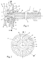
- FIG. 1 shows a section through an assembled camshaft 10 with a variable phase drive mechanism of the invention incorporated into its drive sprocket 30.
- the camshaft assembly comprises an inner shaft 14 surrounded by an outer sleeve or tube 12 which can rotate relative to the shaft 14 through a limited angle.
- One set of cams 16 is directly connected to the outer tube 12.
- a second set of cams 18 is freely journalled on the outer tube 12 and is connected to the inner shaft 14 by pins which pass through tangentially elongated slots in the outer tube 12.
- the end of the inner shaft 14 that projects at the front end of the engine carries the drive sprocket 30 which incorporates a variable phase drive mechanism of the invention which is best understood from the exploded view shown in Figure 3.
- the coupling comprises a drive member 32 in the form of a thick disk 34 which is formed with sprocket teeth 35 and is driven by the engine crankshaft.
- the drive member 32 could equally be part of a chain sprocket or a toothed belt pulley.
- the drive member 32 is formed on its opposite sides with shallow recesses 36 to receive two driven members 38 and 40.
- the first driven member 38 is keyed in for rotation with the inner shaft 14 of the assembled camshaft while the second driven member 40 is connected to the outer tube 12 by bolts 60 that are screwed into the front camshaft support 62.
- the drive member 32 is formed on each side with further arcuate blind recesses 42 and 44 which are covered by the respective driven members 38 and 40 to form sealed hydraulic cavities.
- Each of the cavities is divided into two working chambers by radial vanes 46 and 48.
- Various ports are formed in the drive member 32 to establish a hydraulic connection to the two working chambers.
- the hydraulic controls in this embodiment of the invention are completely separate from one another.
- the cavities 42 and vanes 46 form a first vane-type coupling that rotates the first driven member 38 in relation to the drive member 32, while the cavities 44 on the opposite side of the drive member 32 and the vanes 48 form a second vane-type coupling that adjusts the phase of the second driven member 40.
- the engine front cover 70 is formed with a spigot 72 that is received in a bore at the front end of the inner shaft 14. Suitable rotary seals are provided between the stationary front cover 70 and the rotating drive and driven members. Hydraulic lines 80, 82, in the engine front cover, communicate with ports 90 and 92 respectively that are formed in the driven member 40 and the drive member 32 and that lead to the working chambers on the opposite sides of the vanes 48. Similarly, hydraulic lines 84 and 86 in the front cover 70 communicate with ports 94 and 96 respectively that are formed in the drive member 32 and the driven member 38, and that lead to the working chambers on the opposite sides of the vanes 46.
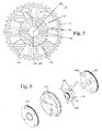
- the drive mechanism of the second embodiment of the invention comprises a drive member 132 in the form of an annular ring having teeth to enable it to be driven in synchronism with the engine crankshaft.
- the drive member 132 in this case is formed with radially inwardly extending vanes 134.
- the first driven member 138 has the form of a hub that is secured by means of a bolt 139 (see Figure 4) for rotation with the inner shaft 14 of the assembled camshaft 10.
- a second set of vanes 140 projects radially from the central hub of the first driven member.
- the second driven member 142 is in the form of a disc that is formed integrally with (or it may be connected to) the camshaft end bearing 62 for rotation with the outer tube 12 of the assembled camshaft 10.
- the plate 142 has four arcuate projections 144 which serve, as will be described below, to define the cavities.
- a cover plate is secured to the projections 144 with the driven member 138 and the drive member 132 sandwiched axially between the driven member 142 and the cover plate 146.
- each cavity has radial end surface defined by the side walls of two of the projections 144.
- the radially inner surface of each cavity is defined by the radially outer surface of the hub of the driven member 138 and the radially outer surface of each cavity is defined by the radially inner surface of the annular drive member 132.
- the axial end surfaces of the cavities are defined by the driven member 142 and the cover plate 146.
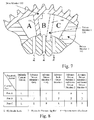
- Each of the cavities is divided into three working chambers by two vanes, the first being one of the vanes 140 projecting outwards from the driven member 138 and the second being one of the vanes 134 projecting radially inwards from the drive member 132.
- the driven member 138 is formed with ports 172, 174 that open into the cavities one on each side of each vane 140.
- the driven member 142 on the other hand is formed with angled drillings 176 that communicate with each cavity in the working chamber between the vane 134 connected to the drive member 132 and the adjacent projection 144 of the driven member 142.
- the engine has a front cover 180 that has a spigot projecting into and suitably sealed relative to the hub of the driven member 138.
- Three hydraulic lines 182, 184, 186 in the cover 180 communicate respectively with the ports 172, 174 and 176 that lead of the three working chambers of each cavity.
- one of the four cavities is shown schematically as being connected to three ports A, B and C corresponding respectively to the ports 176, 174, 172 described above.
- the table of Figure 8 shows the necessary connections to the ports A, B and C to achieve the desired independent control of the phase of the two driven members 138 and 142.
- Each of the lines 182, 184 and 186 is connected to a control valve which has three positions, termed L, P and E in the table of Figure 8. In the first position, all the ports connected to the line are closed so that oil can neither enter not leave the associated working chambers. In the position designated P in Figure 8, Pressure is applied to the associated working chambers and in the position designated E, the associated working chambers are connected to Exhaust, i.e. to a drain line leading back to the oil pump or a reservoir connected to the oil pump.
- any one or both of the driven members 138 and 142 can be moved in either direction relative to the drive member 132 by suitable selection of the position of the control valves connected to then lines 182, 184, 186.
- Port A In the second column of the table, Port A is locked so that the second driven member 142 cannot move relative to the drive member 132. Ports B and C can now be connected to pressure and exhaust respectively to advance the first drive member 138 (or the connections may be reversed to retard the first driven member 138 without affecting the phase of the second driven member 142.
- the third column shows that by locking working chamber B, the phase of the first driven member 138 may be maintained constant while the pressures in the working chambers A and C can be set to advance (or retard) the phase of the second driven member 142.
- port C is locked, thereby locking the phase of the driven members 138 and 142 relative to one another.
- Ports A and B can then be connected to the pressure supply and the return line to move the two driven members at the same time in the desired direction relative to the drive member.
- Connecting ports A and B to high pressure P while port C is connected to exhaust has the effect of collapsing working chamber C and maximising the volume of working chambers A and B. This corresponds to advancing the first driven member 138 and retarding the second driven member 142 relative to the drive member 132.
- connecting ports A and B to exhaust while pressurising chamber C has the effect or stacking the two vanes 134 and 140 at the left hand end of the cavity as shown in Figure 7; this corresponding to advancing of the second driven members 142 and retarding the phase of the first driven member 138.
- both of the illustrated embodiments of the invention described above have been shown driving an assembled camshaft having two cam sets that can move relative to another as they both rotate about the same axis.
- one of the driven members 242 is a sprocket that is freely journalled about a solid camshaft and is coupled by a chain 220 for rotation with a second camshaft 214 on which are formed the second set of cams.
- the second camshaft 216 is arranged parallel to the first camshaft 214 which is concentric with the drive member 232.
- the internal construction of the variable phase drive mechanism is in other respects the same as that of the embodiment of Figure 5 and need not therefore be described in greater detail.
- the two cam sets need not act on inlet and exhaust valves and it is alternatively possible, for example, to use the variable phase drive mechanism of the invention to drive cam sets acting on separate inlet valves or separate exhaust valves in any engine having multiple valves per cylinder.
- the phase variation can be used to alter the duration of an intake or exhaust event by effectively allowing its commencement time and its termination time to be adjusted independently of one another.
Applications Claiming Priority (2)
| Application Number | Priority Date | Filing Date | Title |
|---|---|---|---|
| GB0028175A GB2369175A (en) | 2000-11-18 | 2000-11-18 | Variable phase coupling |
| GB0028175 | 2000-11-18 |
Publications (3)
| Publication Number | Publication Date |
|---|---|
| EP1234954A2 true EP1234954A2 (fr) | 2002-08-28 |
| EP1234954A3 EP1234954A3 (fr) | 2003-01-22 |
| EP1234954B1 EP1234954B1 (fr) | 2006-07-19 |
Family
ID=9903433
Family Applications (1)
| Application Number | Title | Priority Date | Filing Date |
|---|---|---|---|
| EP01000590A Expired - Lifetime EP1234954B1 (fr) | 2000-11-18 | 2001-11-02 | Variateur de phase |
Country Status (4)
| Country | Link |
|---|---|
| US (1) | US6725817B2 (fr) |
| EP (1) | EP1234954B1 (fr) |
| DE (1) | DE60121540T2 (fr) |
| GB (1) | GB2369175A (fr) |
Cited By (15)
| Publication number | Priority date | Publication date | Assignee | Title |
|---|---|---|---|---|
| GB2413168A (en) * | 2004-04-13 | 2005-10-19 | Mechadyne Plc | Variable phase drive mechanism |
| GB2415745A (en) * | 2004-06-29 | 2006-01-04 | Mechadyne Plc | Engine with VVT drives an auxiliary device from an unphased part of the camshaft |
| EP1614867A1 (fr) * | 2004-06-21 | 2006-01-11 | Mechadyne plc | Moteur à distribution variable |
| WO2006050686A1 (fr) * | 2004-11-09 | 2006-05-18 | Mahle Ventiltrieb Gmbh | Support entre deux arbres a cames coaxiaux destine notamment a des moteurs de vehicules automobiles |
| DE102005039751A1 (de) * | 2005-08-23 | 2007-03-01 | Mahle International Gmbh | Nockenwelle |
| DE102006041918A1 (de) * | 2006-09-07 | 2008-03-27 | Mahle International Gmbh | Verstellbare Nockenwelle |
| DE102008019746A1 (de) | 2008-04-19 | 2009-10-22 | Schaeffler Kg | Vorrichtung zur variablen Einstellung der Steuerzeiten von Gaswechselventilen einer Brennkraftmaschine |
| EP2221457A2 (fr) | 2009-02-23 | 2010-08-25 | Mechadyne PLC | Système de déphasage d'arbre à cames |
| WO2011010241A1 (fr) | 2009-07-23 | 2011-01-27 | Mechadyne Plc | Ensemble de mise en phase pour moteur à combustion interne |
| EP2415979A1 (fr) | 2010-08-04 | 2012-02-08 | Hydraulik-Ring GmbH | Déphaseur d'arbre à cames |
| US8201528B2 (en) | 2008-01-04 | 2012-06-19 | Hilite Germany Gmbh | Doubled cam shaft adjuster in layered construction |
| CN103492680A (zh) * | 2011-04-04 | 2014-01-01 | 谢夫勒科技股份两合公司 | 凸轮轴调节器 |
| CN103857882A (zh) * | 2011-10-15 | 2014-06-11 | 大众汽车有限公司 | 用于内燃机的气门传动装置 |
| EP2915964A1 (fr) | 2014-03-03 | 2015-09-09 | Mechadyne International Limited | Moteur à combustion interne |
| EP3141711A1 (fr) | 2015-09-11 | 2017-03-15 | Mechadyne International Limited | Déphaseur d'arbre à cames double |
Families Citing this family (67)
| Publication number | Priority date | Publication date | Assignee | Title |
|---|---|---|---|---|
| GB2401150A (en) | 2003-04-29 | 2004-11-03 | Mechadyne Plc | I.c. engine camshaft oil supply arrangement |
| US7036473B1 (en) * | 2003-10-14 | 2006-05-02 | Grant Goracy | Adjustable cam shaft |
| JP2005155373A (ja) * | 2003-11-21 | 2005-06-16 | Mitsubishi Electric Corp | バルブタイミング調整装置 |
| DE102004020124A1 (de) * | 2004-04-24 | 2005-11-17 | Aft Atlas Fahrzeugtechnik Gmbh | Vorrichtung zur Einstellung von Ventilsteuerzeiten sowie Brennkraftmaschine mit einer derartigen Vorrichtung |
| GB2421557B (en) * | 2004-12-23 | 2009-10-28 | Mechadyne Plc | Vane-type phaser |
| GB2423565A (en) * | 2005-02-23 | 2006-08-30 | Mechadyne Plc | Inner camshaft of SCP assembly receives drive via sleeve on outer tube |
| GB2424256A (en) * | 2005-03-16 | 2006-09-20 | Mechadyne Ltd | SCP assembly with spring mounted on camshaft rather than within phaser housing |
| GB0505497D0 (en) * | 2005-03-18 | 2005-04-20 | Mechadyne Plc | Camshaft to phaser coupling |
| GB2432645B (en) * | 2005-11-28 | 2010-12-29 | Mechadyne Plc | Variable phase drive coupling |
| DE102005061187A1 (de) * | 2005-12-21 | 2007-06-28 | Mahle International Gmbh | Nockenwelle |
| DE202005021716U1 (de) | 2005-12-24 | 2009-07-02 | Mahle International Gmbh | Nockenwelle |
| GB2433974A (en) * | 2006-01-04 | 2007-07-11 | Mechadyne Plc | Mounting of a SCP (single cam phaser) camshaft on an engine |
| DE102006024793A1 (de) * | 2006-05-27 | 2007-11-29 | Mahle International Gmbh | Nockenwelle |
| JP4184392B2 (ja) * | 2006-06-27 | 2008-11-19 | 本田技研工業株式会社 | 電動機 |
| GB2444943B (en) * | 2006-12-19 | 2011-07-13 | Mechadyne Plc | Camshaft and phaser assembly |
| GB2445570B (en) * | 2007-01-09 | 2011-04-06 | Mechadyne Plc | Rotary hydraulic coupling |
| DE102007007758A1 (de) * | 2007-02-16 | 2008-08-21 | Mahle International Gmbh | Ventiltrieb eines Hubkolben-Verbrennungsmotors |
| DE102007017514A1 (de) * | 2007-04-13 | 2008-10-16 | Mahle International Gmbh | Nockenwelle |
| US8146551B2 (en) * | 2007-06-19 | 2012-04-03 | Borgwarner Inc. | Concentric cam with phaser |
| EP2171222B1 (fr) * | 2007-07-02 | 2017-11-29 | BorgWarner Inc. | Came concentrique avec clapets anti-retour dans la bobine pour un déphaseur |
| DE102007042053A1 (de) * | 2007-09-05 | 2009-03-12 | Mahle International Gmbh | Kolbenmotor |
| WO2009067789A1 (fr) * | 2007-11-26 | 2009-06-04 | Magna Powertrain Inc. | Arbre à cames concentrique avec entraînement de phase électrique |
| US7841311B2 (en) * | 2008-01-04 | 2010-11-30 | Hilite International Inc. | Variable valve timing device |
| DE102008005292B4 (de) | 2008-01-19 | 2021-01-28 | Schaeffler Technologies AG & Co. KG | Nockenwellenverstellsystem |
| US7789054B2 (en) | 2008-03-10 | 2010-09-07 | Gm Global Technology Operations, Inc. | Twin cam phaser for dual independent cam phasing |
| US7866293B2 (en) * | 2008-03-12 | 2011-01-11 | GM Global Technology Operations LLC | Concentric camshaft with improved torque resistance |
| US7849829B2 (en) | 2008-03-12 | 2010-12-14 | Gm Global Technology Operations, Inc. | Concentric camshaft with independent bearing surface for floating lobes |
| US8028666B2 (en) | 2008-03-12 | 2011-10-04 | GM Global Technology Operations LLC | Concentric camshaft with bearing sleeve and method of debris removal |
| US7966983B2 (en) * | 2008-04-10 | 2011-06-28 | GM Global Technology Operations LLC | Concentric camshaft with varying wall geometry and method of assembly |
| US7975663B2 (en) * | 2008-04-15 | 2011-07-12 | GM Global Technology Operations LLC | Dual-equal cam phasing with variable overlap |
| DE102008019745A1 (de) | 2008-04-19 | 2009-10-22 | Schaeffler Kg | Vorrichtung zur variablen Einstellung der Steuerzeiten von Gaswechselventilen einer Brennkraftmaschine |
| DE102008023098A1 (de) | 2008-05-09 | 2009-12-17 | Hydraulik-Ring Gmbh | Doppelter Nockenwellenversteller in Schichtaufbau |
| US20100012060A1 (en) * | 2008-07-21 | 2010-01-21 | Gm Global Technology Operations, Inc. | Split Lobe Design of Concentric Camshaft |
| US8584634B2 (en) * | 2008-09-19 | 2013-11-19 | Borgwarner Inc. | Phaser built into a camshaft or concentric camshafts |
| DE102008050776A1 (de) * | 2008-10-08 | 2010-04-15 | Daimler Ag | Ventiltriebvorrichtung |
| DE102009041873A1 (de) * | 2008-10-09 | 2010-04-15 | Schaeffler Kg | Nockenwellenversteller für die innere Nockenwelle eines konzentrischen Nockenwellenaufbaus |
| GB2467333A (en) | 2009-01-30 | 2010-08-04 | Mechadyne Plc | Single camshaft phaser and camshaft for i.c. engines |
| WO2010096437A2 (fr) | 2009-02-17 | 2010-08-26 | Cummins Inc. | Appareil, système et procédé d'actionnement de soupapes variables |
| BR112012007632A2 (pt) | 2009-10-05 | 2018-06-05 | Schaeffler Technologies Ag | disposição de eixo de cames |
| KR101675613B1 (ko) | 2009-10-05 | 2016-11-11 | 섀플러 테크놀로지스 아게 운트 코. 카게 | 캠 샤프트 장치 |
| JP5093521B2 (ja) | 2009-11-06 | 2012-12-12 | 三菱自動車工業株式会社 | 内燃機関の可変動弁装置 |
| US8371257B2 (en) * | 2010-03-10 | 2013-02-12 | GM Global Technology Operations LLC | Engine with dual cam phaser for concentric camshaft |
| US8448617B2 (en) | 2010-10-20 | 2013-05-28 | GM Global Technology Operations LLC | Engine including camshaft with partial lobe |
| GB2487227A (en) | 2011-01-14 | 2012-07-18 | Mechadyne Plc | Spool valve for simultaneous control of two output members |
| CN103348100B (zh) | 2011-02-09 | 2016-06-08 | 博格华纳公司 | 同中心组装在同心凸轮轴系统上的双相位器 |
| DE102011001301B4 (de) | 2011-03-16 | 2017-09-21 | Hilite Germany Gmbh | Schwenkmotorversteller |
| US8695545B2 (en) * | 2011-03-31 | 2014-04-15 | Toyota Jidosha Kabushiki Kaisha | Phase changing device of camshaft |
| DE102011006689A1 (de) * | 2011-04-04 | 2012-10-04 | Schaeffler Technologies Gmbh & Co. Kg | Nockenwellenversteller |
| DE102011007883A1 (de) * | 2011-04-21 | 2012-10-25 | Schaeffler Technologies AG & Co. KG | Nockenwellenversteller |
| DE102011076652B4 (de) * | 2011-05-27 | 2017-06-01 | Schwäbische Hüttenwerke Automotive GmbH | Vorrichtung zur Verstellung der relativen Drehwinkelposition geschachtelter Nockenwellen |
| DE102011079183A1 (de) * | 2011-07-14 | 2013-01-17 | Schaeffler Technologies AG & Co. KG | Nockenwellenversteller |
| DE102011052822A1 (de) | 2011-08-18 | 2013-02-21 | Thyssenkrupp Presta Teccenter Ag | Nockenwelle, insbesondere für Kraftfahrzeugmotoren |
| US9284861B2 (en) | 2011-08-30 | 2016-03-15 | Borgwarner, Inc. | Oil passage design for a phaser or dual phaser |
| CN103842628B (zh) * | 2011-10-14 | 2018-04-17 | 博格华纳公司 | 一个或多个凸轮相位器的共享油道和/或控制阀 |
| CN104246153B (zh) | 2012-05-18 | 2016-11-09 | 舍弗勒技术股份两合公司 | 凸轮轴单元 |
| DE112013002564A5 (de) * | 2012-05-18 | 2015-02-05 | Schaeffler Technologies Gmbh & Co. Kg | Nockenwelleneinheit |
| DE102012220543A1 (de) * | 2012-11-12 | 2014-05-15 | Schaeffler Technologies Gmbh & Co. Kg | Nockenwellenverstelleinrichtung |
| DE102013221886A1 (de) | 2013-10-28 | 2015-04-30 | Borgwarner Inc. | Brennkraftmaschine mit einem Phasenversteller sowie dazugehöriges Regelverfahren |
| US20160032791A1 (en) * | 2014-07-31 | 2016-02-04 | Cummins, Inc. | Concentric dual independent camshaft phaser for dual overhead camshaft valve train |
| CN110195624B (zh) | 2018-02-27 | 2022-05-17 | 博格华纳公司 | 凸轮轴承间的凸轮相位器 |
| US10947870B2 (en) | 2018-05-25 | 2021-03-16 | Schaeffler Technologies AG & Co. KG | Coupling for a camshaft phaser arrangement for a concentric camshaft assembly |
| US10557384B2 (en) | 2018-06-01 | 2020-02-11 | Schaeffler Technologies AG & Co. KG | Coupling for a camshaft phaser arrangement for a concentric camshaft assembly |
| CN111140305B (zh) | 2018-11-01 | 2024-02-02 | 博格华纳公司 | 凸轮相位器凸轮轴联接 |
| US10590811B1 (en) | 2018-11-16 | 2020-03-17 | Schaeffler Technologies AG & Co. KG | Coupler for a camshaft phaser arrangement for a concentric camshaft assembly |
| US10612429B1 (en) | 2018-11-16 | 2020-04-07 | Schaeffler Technologies AG & Co. KG | Coupling for a camshaft phaser arrangement for a concentric camshaft assembly |
| US10815842B2 (en) | 2018-12-20 | 2020-10-27 | Schaeffler Technologies AG & Co. KG | Camshaft phaser arrangement for a concentric camshaft assembly |
| US10711660B1 (en) | 2019-06-13 | 2020-07-14 | Schaeffler Technologies AG & Co. KG | Camshaft connector of an electric-hydraulic camshaft phaser assembly |
Citations (3)
| Publication number | Priority date | Publication date | Assignee | Title |
|---|---|---|---|---|
| US5002023A (en) | 1989-10-16 | 1991-03-26 | Borg-Warner Automotive, Inc. | Variable camshaft timing for internal combustion engine |
| GB2319071A (en) | 1996-10-02 | 1998-05-13 | Denso Corp | Rotational phase adjusting apparatus |
| EP0924393A2 (fr) | 1997-12-17 | 1999-06-23 | Dr.Ing. h.c.F. Porsche Aktiengesellschaft | Dispositif hydraulique de variation de la position angulaire d'un arbre par rapport à une roue d'entraínement |
Family Cites Families (13)
| Publication number | Priority date | Publication date | Assignee | Title |
|---|---|---|---|---|
| DE2822147C3 (de) * | 1978-05-20 | 1982-02-11 | Volkswagenwerk Ag, 3180 Wolfsburg | Nockenwellenanordnung, insbesondere für eine Brennkraftmaschine |
| JPS59110816A (ja) * | 1982-12-15 | 1984-06-26 | Fuji Heavy Ind Ltd | バルブ開閉時期可変装置 |
| US5046460A (en) * | 1989-10-16 | 1991-09-10 | Borg-Warner Automotive Transmission & Engine Components Corporation | Variable camshaft timing for internal combustion engine |
| EP0582846B1 (fr) * | 1992-08-13 | 1996-04-24 | Bayerische Motoren Werke Aktiengesellschaft | Moteur à combustion interne à pistons avec deux soupapes de distribution des gaz par cylindre |
| US5497738A (en) * | 1992-09-03 | 1996-03-12 | Borg-Warner Automotive, Inc. | VCT control with a direct electromechanical actuator |
| US5235939A (en) * | 1992-11-05 | 1993-08-17 | Ford Motor Company | Automotive engine torsional pulse enhancer |
| US5233948A (en) * | 1992-12-10 | 1993-08-10 | Ford Motor Company | Variable cycle engine |
| DE4306606A1 (de) * | 1993-03-03 | 1994-09-08 | Bayerische Motoren Werke Ag | Hubkolben-Brennkraftmaschine mit einer Nockenwellen-Antriebsverstelleinheit |
| DE19514786C2 (de) * | 1995-04-21 | 2002-08-14 | Audi Ag | Vorrichtung zum diskreten Verstellen der Phasenlage zumindest zweier Nockenwellen |
| JPH10184322A (ja) * | 1996-12-24 | 1998-07-14 | Aisin Seiki Co Ltd | 弁開閉時期制御装置 |
| JP3539182B2 (ja) * | 1998-02-20 | 2004-07-07 | トヨタ自動車株式会社 | 可変バルブタイミング装置 |
| JP4036401B2 (ja) * | 1998-03-27 | 2008-01-23 | ヤマハ発動機株式会社 | 可変バルブタイミング装置を備えた4サイクルエンジン |
| GB2346948A (en) * | 1999-02-18 | 2000-08-23 | Mechadyne Int Plc | Variable phase mechanism |
-
2000
- 2000-11-18 GB GB0028175A patent/GB2369175A/en not_active Withdrawn
-
2001
- 2001-11-02 EP EP01000590A patent/EP1234954B1/fr not_active Expired - Lifetime
- 2001-11-02 DE DE60121540T patent/DE60121540T2/de not_active Expired - Lifetime
- 2001-11-14 US US10/004,323 patent/US6725817B2/en not_active Expired - Lifetime
Patent Citations (3)
| Publication number | Priority date | Publication date | Assignee | Title |
|---|---|---|---|---|
| US5002023A (en) | 1989-10-16 | 1991-03-26 | Borg-Warner Automotive, Inc. | Variable camshaft timing for internal combustion engine |
| GB2319071A (en) | 1996-10-02 | 1998-05-13 | Denso Corp | Rotational phase adjusting apparatus |
| EP0924393A2 (fr) | 1997-12-17 | 1999-06-23 | Dr.Ing. h.c.F. Porsche Aktiengesellschaft | Dispositif hydraulique de variation de la position angulaire d'un arbre par rapport à une roue d'entraínement |
Cited By (25)
| Publication number | Priority date | Publication date | Assignee | Title |
|---|---|---|---|---|
| GB2413168A (en) * | 2004-04-13 | 2005-10-19 | Mechadyne Plc | Variable phase drive mechanism |
| EP1614867A1 (fr) * | 2004-06-21 | 2006-01-11 | Mechadyne plc | Moteur à distribution variable |
| CN1977091B (zh) * | 2004-06-29 | 2011-08-31 | 麦加戴恩公共有限公司 | 具可变气门正时的发动机 |
| GB2415745A (en) * | 2004-06-29 | 2006-01-04 | Mechadyne Plc | Engine with VVT drives an auxiliary device from an unphased part of the camshaft |
| WO2006000832A1 (fr) * | 2004-06-29 | 2006-01-05 | Mechadyne Plc | Moteur a reglage de distribution variable |
| WO2006050686A1 (fr) * | 2004-11-09 | 2006-05-18 | Mahle Ventiltrieb Gmbh | Support entre deux arbres a cames coaxiaux destine notamment a des moteurs de vehicules automobiles |
| US7588006B2 (en) | 2004-11-09 | 2009-09-15 | Mahle Ventiltrieb Gmbh | Bearing between two coaxial camshafts for automotive engines in particular |
| DE102005039751A1 (de) * | 2005-08-23 | 2007-03-01 | Mahle International Gmbh | Nockenwelle |
| DE102006041918A1 (de) * | 2006-09-07 | 2008-03-27 | Mahle International Gmbh | Verstellbare Nockenwelle |
| US8453615B2 (en) | 2006-09-07 | 2013-06-04 | Mahle International Gmbh | Adjustable camshaft |
| US8201528B2 (en) | 2008-01-04 | 2012-06-19 | Hilite Germany Gmbh | Doubled cam shaft adjuster in layered construction |
| DE102008019746A1 (de) | 2008-04-19 | 2009-10-22 | Schaeffler Kg | Vorrichtung zur variablen Einstellung der Steuerzeiten von Gaswechselventilen einer Brennkraftmaschine |
| EP2221457A2 (fr) | 2009-02-23 | 2010-08-25 | Mechadyne PLC | Système de déphasage d'arbre à cames |
| WO2011010241A1 (fr) | 2009-07-23 | 2011-01-27 | Mechadyne Plc | Ensemble de mise en phase pour moteur à combustion interne |
| CN102439265B (zh) * | 2009-07-23 | 2015-02-11 | 麦加戴恩国际有限公司 | 用于内燃机的移相器组件 |
| CN102439265A (zh) * | 2009-07-23 | 2012-05-02 | 米查戴尼股份有限公司 | 用于内燃机的移相器组件 |
| EP2415979A1 (fr) | 2010-08-04 | 2012-02-08 | Hydraulik-Ring GmbH | Déphaseur d'arbre à cames |
| US8677960B2 (en) | 2010-08-04 | 2014-03-25 | Hilite Germany Gmbh | Camshaft adjuster, in particular with camshaft |
| DE102010033296A1 (de) | 2010-08-04 | 2012-02-09 | Hydraulik-Ring Gmbh | Nockenwellenversteller, insbesondere mit Nockenwelle |
| CN103492680A (zh) * | 2011-04-04 | 2014-01-01 | 谢夫勒科技股份两合公司 | 凸轮轴调节器 |
| CN103857882A (zh) * | 2011-10-15 | 2014-06-11 | 大众汽车有限公司 | 用于内燃机的气门传动装置 |
| EP2766582A1 (fr) * | 2011-10-15 | 2014-08-20 | Volkswagen Aktiengesellschaft | Commande de soupapes pour moteur à combustion interne |
| EP2915964A1 (fr) | 2014-03-03 | 2015-09-09 | Mechadyne International Limited | Moteur à combustion interne |
| EP3141711A1 (fr) | 2015-09-11 | 2017-03-15 | Mechadyne International Limited | Déphaseur d'arbre à cames double |
| WO2017042302A1 (fr) | 2015-09-11 | 2017-03-16 | Mechadyne International Ltd. | Déphaseur d'arbre à cames double |
Also Published As
| Publication number | Publication date |
|---|---|
| EP1234954B1 (fr) | 2006-07-19 |
| DE60121540T2 (de) | 2007-07-26 |
| EP1234954A3 (fr) | 2003-01-22 |
| DE60121540D1 (de) | 2006-08-31 |
| GB2369175A (en) | 2002-05-22 |
| US6725817B2 (en) | 2004-04-27 |
| US20020059910A1 (en) | 2002-05-23 |
| GB0028175D0 (en) | 2001-01-03 |
Similar Documents
| Publication | Publication Date | Title |
|---|---|---|
| EP1234954B1 (fr) | Variateur de phase | |
| EP1828552B1 (fr) | Dephaseur de type a aube | |
| EP0213154B1 (fr) | Appareil a fluide a mouvement rotatif | |
| US7270096B2 (en) | Variable phase drive mechanism | |
| US6247434B1 (en) | Multi-position variable camshaft timing system actuated by engine oil | |
| US7137371B2 (en) | Phaser with a single recirculation check valve and inlet valve | |
| US9284861B2 (en) | Oil passage design for a phaser or dual phaser | |
| DK166741B1 (da) | Roterende hydraulisk maskine med et planetgearstyret ventilsystem | |
| JPS6358269B2 (fr) | ||
| US3910732A (en) | Gerotor pump or motor | |
| US9080470B2 (en) | Shared oil passages and/or control valve for one or more cam phasers | |
| EP0816643B1 (fr) | Actuateur hydraulique pour moteur à combustion interne | |
| US5516268A (en) | Valve-in-star motor balancing | |
| EP1473443A2 (fr) | Moteur à combustion interne | |
| US5593296A (en) | Hydraulic motor and pressure relieving means for valve plate thereof | |
| JPH05113112A (ja) | エンジンの弁開閉時期可変装置 | |
| JP4645561B2 (ja) | 弁開閉時期制御装置 | |
| JP3960742B2 (ja) | 内燃機関のバルブタイミング制御装置 | |
| JP2002097909A (ja) | 内燃機関のバルブタイミング制御装置 | |
| JPH11159308A (ja) | 弁開閉時期制御装置 | |
| JPH05113109A (ja) | エンジンの弁開閉時期可変装置 | |
| JP2002332811A (ja) | 内燃機関のバルブタイミング制御装置 | |
| JPH0565801A (ja) | 流体圧を利用した回転装置 |
Legal Events
| Date | Code | Title | Description |
|---|---|---|---|
| PUAI | Public reference made under article 153(3) epc to a published international application that has entered the european phase |
Free format text: ORIGINAL CODE: 0009012 |
|
| AK | Designated contracting states |
Kind code of ref document: A2 Designated state(s): AT BE CH CY DE DK ES FI FR GB GR IE IT LI LU MC NL PT SE TR |
|
| AX | Request for extension of the european patent |
Free format text: AL;LT;LV;MK;RO;SI |
|
| PUAL | Search report despatched |
Free format text: ORIGINAL CODE: 0009013 |
|
| AK | Designated contracting states |
Kind code of ref document: A3 Designated state(s): AT BE CH CY DE DK ES FI FR GB GR IE IT LI LU MC NL PT SE TR |
|
| AX | Request for extension of the european patent |
Free format text: AL;LT;LV;MK;RO;SI |
|
| 17P | Request for examination filed |
Effective date: 20030613 |
|
| AKX | Designation fees paid |
Designated state(s): DE FR GB |
|
| GRAP | Despatch of communication of intention to grant a patent |
Free format text: ORIGINAL CODE: EPIDOSNIGR1 |
|
| GRAS | Grant fee paid |
Free format text: ORIGINAL CODE: EPIDOSNIGR3 |
|
| GRAA | (expected) grant |
Free format text: ORIGINAL CODE: 0009210 |
|
| AK | Designated contracting states |
Kind code of ref document: B1 Designated state(s): DE FR GB |
|
| REG | Reference to a national code |
Ref country code: GB Ref legal event code: FG4D |
|
| REF | Corresponds to: |
Ref document number: 60121540 Country of ref document: DE Date of ref document: 20060831 Kind code of ref document: P |
|
| ET | Fr: translation filed | ||
| PLBE | No opposition filed within time limit |
Free format text: ORIGINAL CODE: 0009261 |
|
| STAA | Information on the status of an ep patent application or granted ep patent |
Free format text: STATUS: NO OPPOSITION FILED WITHIN TIME LIMIT |
|
| 26N | No opposition filed |
Effective date: 20070420 |
|
| REG | Reference to a national code |
Ref country code: GB Ref legal event code: 732E Free format text: REGISTERED BETWEEN 20130718 AND 20130724 |
|
| REG | Reference to a national code |
Ref country code: FR Ref legal event code: TP Owner name: MECHADYNE INTERNATIONAL LIMITED, GB Effective date: 20131015 Ref country code: FR Ref legal event code: CD Owner name: MECHADYNE INTERNATIONAL LIMITED, GB Effective date: 20131015 Ref country code: FR Ref legal event code: CJ Effective date: 20131015 |
|
| REG | Reference to a national code |
Ref country code: DE Ref legal event code: R082 Ref document number: 60121540 Country of ref document: DE Representative=s name: PATENTANWAELTE TER SMITTEN EBERLEIN RUETTEN PA, DE Ref country code: DE Ref legal event code: R082 Ref document number: 60121540 Country of ref document: DE Representative=s name: PATENTANWAELTE TER SMITTEN EBERLEIN-VAN HOOF R, DE |
|
| REG | Reference to a national code |
Ref country code: FR Ref legal event code: PLFP Year of fee payment: 15 |
|
| REG | Reference to a national code |
Ref country code: FR Ref legal event code: PLFP Year of fee payment: 16 |
|
| REG | Reference to a national code |
Ref country code: FR Ref legal event code: PLFP Year of fee payment: 17 |
|
| PGFP | Annual fee paid to national office [announced via postgrant information from national office to epo] |
Ref country code: DE Payment date: 20191125 Year of fee payment: 19 |
|
| REG | Reference to a national code |
Ref country code: DE Ref legal event code: R082 Ref document number: 60121540 Country of ref document: DE Representative=s name: TERPATENT PATENTANWAELTE TER SMITTEN EBERLEIN-, DE |
|
| PGFP | Annual fee paid to national office [announced via postgrant information from national office to epo] |
Ref country code: FR Payment date: 20191121 Year of fee payment: 19 |
|
| PGFP | Annual fee paid to national office [announced via postgrant information from national office to epo] |
Ref country code: GB Payment date: 20191126 Year of fee payment: 19 |
|
| REG | Reference to a national code |
Ref country code: DE Ref legal event code: R119 Ref document number: 60121540 Country of ref document: DE |
|
| GBPC | Gb: european patent ceased through non-payment of renewal fee |
Effective date: 20201102 |
|
| PG25 | Lapsed in a contracting state [announced via postgrant information from national office to epo] |
Ref country code: FR Free format text: LAPSE BECAUSE OF NON-PAYMENT OF DUE FEES Effective date: 20201130 |
|
| PG25 | Lapsed in a contracting state [announced via postgrant information from national office to epo] |
Ref country code: DE Free format text: LAPSE BECAUSE OF NON-PAYMENT OF DUE FEES Effective date: 20210601 Ref country code: GB Free format text: LAPSE BECAUSE OF NON-PAYMENT OF DUE FEES Effective date: 20201102 |