EP2415979A1 - Déphaseur d'arbre à cames - Google Patents
Déphaseur d'arbre à cames Download PDFInfo
- Publication number
- EP2415979A1 EP2415979A1 EP11169788A EP11169788A EP2415979A1 EP 2415979 A1 EP2415979 A1 EP 2415979A1 EP 11169788 A EP11169788 A EP 11169788A EP 11169788 A EP11169788 A EP 11169788A EP 2415979 A1 EP2415979 A1 EP 2415979A1
- Authority
- EP
- European Patent Office
- Prior art keywords
- camshaft
- stator
- connecting means
- rotor
- camshaft adjuster
- Prior art date
- Legal status (The legal status is an assumption and is not a legal conclusion. Google has not performed a legal analysis and makes no representation as to the accuracy of the status listed.)
- Granted
Links
Images


Classifications
-
- F—MECHANICAL ENGINEERING; LIGHTING; HEATING; WEAPONS; BLASTING
- F01—MACHINES OR ENGINES IN GENERAL; ENGINE PLANTS IN GENERAL; STEAM ENGINES
- F01L—CYCLICALLY OPERATING VALVES FOR MACHINES OR ENGINES
- F01L1/00—Valve-gear or valve arrangements, e.g. lift-valve gear
- F01L1/34—Valve-gear or valve arrangements, e.g. lift-valve gear characterised by the provision of means for changing the timing of the valves without changing the duration of opening and without affecting the magnitude of the valve lift
- F01L1/344—Valve-gear or valve arrangements, e.g. lift-valve gear characterised by the provision of means for changing the timing of the valves without changing the duration of opening and without affecting the magnitude of the valve lift changing the angular relationship between crankshaft and camshaft, e.g. using helicoidal gear
- F01L1/3442—Valve-gear or valve arrangements, e.g. lift-valve gear characterised by the provision of means for changing the timing of the valves without changing the duration of opening and without affecting the magnitude of the valve lift changing the angular relationship between crankshaft and camshaft, e.g. using helicoidal gear using hydraulic chambers with variable volume to transmit the rotating force
Definitions
- the present invention relates to a valve train of an internal combustion engine with a double camshaft.
- US-A-2,911,956 (Applicant: Smith, filing date: 07.01.1959) describes a plate-like positioner by which pivotal movement of a first plate continues to affect the pivotal range of a second plate and so forth.
- WO 01/12996 A1 (Applicant: Raikamo, priority date: 17.08.1999) shows in FIG. 5a a two-stator shaft adjustment system in which the rotor is limited in its pivoting range by the rotation of a first and second stator.
- auxiliary cam With an auxiliary cam, the cam contour of the main cam of a camshaft can be extended to control the associated gas exchange valve a second time offset to the main event, thus allowing a recharging of the or another outflow from the cylinder.
- Another mode of operation of a camshaft with adjustable double cam events is in the DE 10 2004 023 451 A1 (Applicant: General Motors Corp., priority date: 16.05.2003).
- JP 11 17 31 20 Applicant: Mitsubishi Motors Corp. Date of filing: 08.12.1997) and WO 1992/012333 (Applicant: Porsche AG, priority date: 12.01.1991).
- a camshaft adjuster for the relative rotation of a hollow camshaft and arranged parallel to the first sprocket second sprocket is in the US Pat. No. 6,253,719 B1 (Patentee: Mechadyne PLC, priority date: 18.02.1999). Instead of arranging the two disc-like Kettenradversteller side by side, can be seen in the pictures of the US Pat. No.
- connection for a double camshaft is the EP 1 696 107 A1 (Applicant: Mechadyne PLC, priority date: 23.02.2005), in which by the use of transverse pins both a camshaft phaser and a single cam can be connected to the double-guided camshaft.
- the pin is to be fitted with a clearance in the transverse bore of the camshaft.
- Camshaft adjuster can be connected to split camshafts, is the drawings of the DE 101 02 767 A1 (Applicant: Volkswagen AG, filing date: 23.01.2001).
- Each camshaft controls a type of gas exchange valves. It is thus vorzuschhalten a camshaft adjuster for the gas inlet valves and a camshaft adjuster for the Gausauslassventile.
- the camshaft adjusters are arranged on half of their respective camshaft.
- a gas exchange valve control shaft which is composed of two intermeshing, preferably coaxially arranged, the outer camshaft enclosing the inner camshaft, is also sometimes referred to as a double camshaft.
- a double camshaft is a double-camshaft. With the term camshaft experts often associate a single, longitudinally extending shaft, on which all cams are arranged stationary to each other.
- camshaft adjuster can be connected to a corresponding camshaft to reliably quickly and possibly repeatedly interchangeable to revise the valve train of an internal combustion engine.
- the camshaft adjuster can be adjusted or aligned with the camshaft during assembly.
- the individual cam groups and cams to the other cams and cam groups are to be aligned with each other reliably.
- a rotor which is arranged in a certain angular range movable back and forth between webs of a stator, which may also be designed as part of the enclosing housing, may also be referred to as a rotorcraft.
- the term rotorcraft refers rather to the wing-like appearance of the central, central, pivoting camshaft connecting member, which is often referred to as the output body, while the term rotor refers more to the rotating property of the driven body over otherwise usual axiallinearen adjustment.
- the camshaft adjuster is part of a variable valve train of an internal combustion engine.
- the internal combustion engine has at least one gas exchange valve control shaft.
- the gas exchange valve control shaft has two concentrically arranged camshafts, which are rotatably adjustable relative to each other, so that at least two cams are mutually angularly rotatable.
- the camshaft is set in a rotational angle-dependent relative relationship to a reference shaft. It is particularly advantageous if the two camshafts can be regarded as independent camshafts.
- Each camshaft has a maximum angular range which can be swept over independently of the other camshaft.
- the exhaust valve of an internal combustion engine is often constructed with a camshaft and a pivoting camshaft phaser for changing the relative position of the camshaft to a second shaft for exhaust-gas reasons.
- the second shaft is a crankshaft or drive shaft.
- the camshaft adjuster has at least the rotary components rotor and stator.
- the components may be referred to as rotational components, because they are mutually rotatable variable and so can take different phase relationships to each other.
- the rotating components form between them hydraulic chambers with variable, especially opposing, volumes. By a pivoting rotor movement, the respective chamber is larger or smaller.
- At least one of the rotary components with the camshaft is connected by a pin engaging in the camshaft such that positional changes of the rotor are transmitted to the stator by the pin or a pin-like connecting means on the camshaft.
- the invention proposes a solution in which the additional tilting can be reduced by a connected camshaft adjuster.
- the connection during assembly is fast and reliable to manufacture.
- the connection is detachable again. The connection allows the adjustment of the camshaft with respect to the camshaft adjuster.
- the Schwenkrotorisch working phaser is occasionally referred to as Schwenkenkisch working phaser, although no motor function, but only a location choice by the camshaft adjuster, in particular according to the rotary vane principle is realized realized.
- the valve train comprises a double camshaft with an inner camshaft and an outer camshaft.
- the two camshafts are preferably guided coaxially.
- the angular position of at least one cam of the inner camshaft is set or obtained to a cam of the outer camshaft.
- the cam of the inner camshaft mounted on the outer camshaft is connected by a pin on the inner camshaft pivotally guided.
- the larger bearing surface of the outer camshaft can be used while the event position of the valvetrain is enabled by adjustment of the inner, less mass camshaft.
- the valve train can be variably adjusted to a reference shaft.
- the valvetrain comprises at least two camshafts.
- the valve train has at least a first and a second camshaft.
- the camshafts are arranged so that two of the camshafts are provided as a coaxially designed double camshaft.
- the double camshaft is considered from the outside as a single camshaft whose cams can be set differently.
- the cams are divided into sets, which can take mutually variable cam positions.
- the camshaft adjuster is preferably a pivoting rotary camshaft adjuster.
- the phaser is fixed at its center by a penetrating connecting means, such as a screw or a central valve, to one of the two camshafts with a first set of rotatable components.
- the phaser has different sets of components that are rotatable relative to one another, such as rotor with vanes, at least one locking pin and oil guide channels.
- a coronary mounting flange of the other so the second camshaft, a maximum radius is formed.
- Such a penetrating connection means may be a screw.
- the connecting means are necessary for the attachment of a second set of rotatable components of the camshaft adjuster.
- the one part of the camshaft adjuster is rotationally synchronous with the first camshaft.
- the other part of the camshaft adjuster is rotationally synchronous with the second Camshaft.
- a double camshaft can be connected cheap, reliable and fast with a suitable camshaft adjuster in this way.
- a valve drive according to the invention can be integrally formed integrally formed on the outer of the two camshafts in an advantageous embodiment of the mounting flange.
- the outer camshaft may thus be a forged camshaft.
- the mounting flange is formed radially outwardly at one end of the camshaft.
- the screws can be mounted several times in the mounting flange. The screws engage the non-positive connection.
- the torque is applied evenly to the camshaft.
- the torque applied to the camshaft adjuster via the drive of the valve train, such as the chain drive, can thus be transmitted to the entire outer camshaft.
- the camshaft adjuster comprises a first set of rotatable components.
- the first set may include a rotor.
- the rotor serves to form hydraulic chambers with at least one further component of the camshaft adjuster, such as a stator.
- the stator belongs to the second set of rotatable components.
- a cut-free space is provided in one of the parts of the component sets .
- the clearance space is arranged in alignment with the orientation of the camshaft. The result is an elongated, easy to join component.
- the at least one clearance space serves to receive the connecting means to be aligned axially with the camshaft.
- the fastening method according to the invention of camshaft adjuster and double camshaft does not require any further installation space for the connecting means.
- the mounting flange can serve as a bearing at the same time.
- the clearance space in the camshaft adjuster has a certain length.
- the length of the clearance space is based on a complete retraction of the connecting means from the mounting flange.
- the diameter of the clearance space is larger than the widest point of the connection means.
- the free cut room merges into a narrow-mouthed guide channel.
- the narrow-mouthed guide channel has an opening size such that the penetrating attachment means can pass through as free of play as possible.
- the free-cutting room narrows to a guide channel.
- the guide channel has the shape of a Schluntes, he is schmmalmundig.
- the guide channel provides the access opening for an operating means.
- the operating means during the attachment may be a screwdriver bit.
- the outer, enveloping component of the camshaft adjuster such as the stator, is equipped in one embodiment with a clearance space.
- the free cut room can represent an oil chamber at the same time.
- the hydraulic fluid can penetrate into the clearance space.
- a part of the penetrating connection means is to be sunk.
- the clearance space is used by the connection means or means. There is no need to reserve another mounting space.
- the further penetrating connecting means or the further penetrating connecting means is or are located within a radius.
- the fictitious or to be formed radius is running within the camshaft adjuster.
- the radius is also centered about the central fastener.
- the radius is smaller than the inner wall of the stator. It is particularly shieldt when the radius is as small as possible, z. B. is at most as large as the rotor core.
- All connecting means are located in the center of the camshaft adjuster. The inertia of the camshaft adjuster are reduced.
- the further cross-connecting means can be located in web-like sections of the enveloping part of the camshaft adjuster. They can also be partially placed in the web-like sections.
- the connecting means or the screws can both partially in the webs and partially outside of the webs, so z. B. in the hydraulic chambers, be settled.
- connecting means of the different types are oriented in opposite directions, then the connecting means can be introduced from different sides into the camshaft adjuster and the valve drive. It is not always the same side of the camshaft adjuster perforated.
- the camshaft adjuster has at least one trough-shaped recess in the web-like sections.
- each web has a trough-like recess.
- the recesses may be present to expand or widen the hydraulic chambers.
- the head of the further thorough connecting means can rest with its camshaft associated side form fit therein. No noteworthy material weakening must be taken into account when the hydraulic chambers pass into the recesses.
- the camshaft adjuster which can be used in particular in a valve train according to the invention, has at least one rotor and at least one stator.
- the camshaft adjuster has at least two rotors and a stator. Rotor and stator are rotatable together. Stator and the at least one rotor form mutually opposite hydraulic chambers, which can be clamped differently. By a pivoting rotor movement of the rotor, the sizes of the hydraulic chambers form.
- the camshaft adjuster is equipped for attachment to a double camshaft with a central penetrating connection means.
- the rotor has at least one clearance space.
- the clearance space is matched in its dimensions to another connecting means for fastening the stator to one of the two camshafts of the double camshaft for disassembly.
- the invention is characterized in that even high torques can be transmitted.
- a double camshaft can be operated with a hitherto conventionally known rotary camshaft phaser, if the connecting means of the second type are provided at the locations designated according to the invention within the camshaft adjuster. All the tests and many years of experience gained in the field of rotary camshaft phasers can be transferred to the valve train with a double camshaft.
- a double camshaft allows the event adjustment, ie the change in the opening and closing behavior of the gas exchange valves, within a single valve train.
- FIG. 1A shows the schematically illustrated open chain case 23 in which the drive means 21, namely the chain, a gear-like connection between a reference shaft 7 and at least one of the camshaft adjuster 3, 5 ensures.
- the camshaft adjuster 3 is also part of the valvetrain 1.
- the camshaft adjuster 5 also engages the reference shaft 7, that on the reference shaft 7, a flywheel 15 for bridging the kinetic unpowered phases of the rotating reference shaft. 7 is available.
- reference shaft 7, which is for example a crankshaft, and one of the two camshaft adjusters 3, 5, ideally both camshaft adjusters 3, 5, instead. If the cross-sectional view of the engine block 31 in FIG. 1B considered, the closer construction of the valve train 1 can be seen.
- the reference shaft 7, the crankshaft, is supported in the crankcase 17 by crankshaft bearings 19. At one end of the reference shaft 7, a flywheel 15 attacks.
- the flywheel 15 stores and transfers kinetic energy from the crankshaft.
- the engine block 31 has a drive means 21, which establishes a mechanically fixed connection between the camshaft adjuster 3 and the reference shaft 7 in a drive means box such as a chain case 23.
- the crankshaft rests on the crankshaft bearings 19.
- the camshaft is as a double camshaft 9 designed.
- the camshaft 9 is located in the camshaft bearing 25 in the cylinder head 27.
- the camshaft in the form of the double camshaft 9 is below a cylinder head cover 29. Due to the double design of the double camshaft 9 two different sets of cams 11, 13 can be controlled differently to each other. Thus, both the intake behavior of the intake gas exchange valves by the cams 11 and the exhaust behavior of the exhaust gas exchange valves by the cams 13 can be controlled by a camshaft. If it is a variable valve train 1, the relative relationships between the cam 11 and the cam 13 with respect to a reference point as the reference shaft 7 can be adjusted. While the drive means 21 acts on the outer circumference of the camshaft adjuster 3, the output force from the camshaft adjuster 3 is discharged via the camshaft adjuster center 33 onto the double camshaft 9.
- a connection between the double camshaft 9 and camshaft adjuster 3 is to be produced in such a way that a reliable connection is provided, which should be possible easily, quickly and with only a few steps during assembly.
- a parallel design of the components to be joined or components to be rotated further shortens the assembly time.
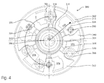
- FIG. 2 shows a first embodiment of a camshaft adjuster 100, the part of a valve train 1 after the Figures 1A and 1B along with the camshaft that is in FIG. 3 is shown as a double camshaft 182.
- FIG. 2 shows a section through the camshaft adjuster 100 of the first embodiment;
- FIG. 3 shows a longitudinal section through the valve train 222.
- the camshaft adjuster 100 is part of the valve train 222. Further belong to the valve train, the double camshaft 182 and the connecting means as the connecting means 156, 158, 160.
- the double camshaft 182 is composed of a first camshaft 184 and a second Camshaft 186 together.
- One of the two camshafts 184, 186 is guided as an inner camshaft within the second camshaft 186.
- On the outer camshaft 186 are first cams 194 and second cams 196.
- the cams 194, 196 may (not in FIG FIG. 3 shown) are next to each other.
- the cams 194, 196 may also be arranged as intermeshing double cams to provide two downstream events for a gas exchange valve.
- One cam 194 follows the rotational movement of one camshaft 184 or 186, while the other cam 196 follows the rotational motion of the other camshaft 186 or 184.
- the camshaft phaser 100 is a camshaft phaser of the rotary blade type.
- the camshaft adjuster 100 has a stator 102 and a rotor 104.
- the stator 102 also rotates synchronously to the reference shaft (but possibly with different rotational speed), which is used as the reference shaft 7 in the form of the crankshaft in FIG. 1B is shown.
- the stator 102 includes the rotor 104 through its stator housing 108.
- the rotor 104 is deployed Rotor core 106 and outgoing from the rotor core 106 wings 140, 142, 144, 146 and 148 together.
- stator vanes 128, 130, 132, 134, 136 have the camshaft adjuster 100.
- a multi-rotor camshaft phaser 140, 142, 144, 146, 148 such as, for example five rotor blades 140, 142, 144, 146, 148.
- the chambers 174, 176 occur in the camshaft adjuster 100 multiple times.
- the stator 102 is not only composed of the stator housing 108, but to the stator 102 includes other components, such as an insert plate 110 (see FIG. 3 ) to form an outer enveloping part 112 (see FIG Figures 2 and 3 ) of the camshaft adjuster 100.
- the stator 102 is trough-shaped to receive the rotor 104 at its center.
- the stator 102 is rotationally configured.
- the camshaft adjuster 100 has a center 120 from which the radius 126 can be removed. On the radius 126 radii are formed, which are referred to as first wreath 122 and second wreath 124. The second ring lies outside of the first ring 122, z. B. it has at least twice the circumference of the first ring 122.
- the camshaft adjuster 100 has different connection means 156, 158, 160.
- the connection means 156, 158, 160 are within a maximum radius 126, which is determined by the inner wall 114 of the stator 102.
- the connecting means 156, 158, 160 assume different tasks.
- a first connecting means 156 provides the connection between rotor 104, more precisely rotor core 106, and one of the camshafts 184, 186 in a frictional manner.
- the inner camshaft 184 is connected to the rotor 104 via the connecting means 156.
- the further connection means 158 (see FIG. 2 ) occurring multiple times in the phaser 100 is known as a screw 164 (see FIG. 3 ) realized.
- the rotor 104 together with other components, such as a hydraulic fluid channel cover 180, forms a first set 116 of rotatable components. Because also the stator 102 during operation of the internal combustion engine, so the engine block 31 (see FIG.
- the stator 102 forms, together with other components, such as the insert plate 110 and the drive wheel 200, a second set 118 of rotatable components.
- the torque from the reference shaft 7 is hydraulically introduced via the rotor core 106 to that in the center 120 of the Camshaft adjuster 100 arranged connecting means 156 transmitted.
- the connecting means 156 is realized as a first, large screw 162, which preferably lies in the center of the valve drive 222, that is, in the center 120 of the camshaft adjuster 100.
- a fixing means 150 for fixedly fixing the rotor 104 to the stator 102 in a locked position.
- sealing strips 154 may be provided in individual wings 146. With a correspondingly accurate production, the sealing strips 154 can be omitted in most wings. Because the stator 102 is assembled from a plurality of parts such as the stator housing 108 and the drive wheel 200, other connecting means, third connecting means 160 must clamp the individual enveloping parts 112 of the camshaft adjuster 100. For this purpose, the stator vanes 128, 130, 132, 134, 136 have special recesses 138, so that the connecting means 160 of the third type can pass through from one part of the stator 102 into the other part of the stator 102.
- the connecting means 158 of the second type are placed in the camshaft adjuster 100.
- the connecting means 158 all lie on a rim 122 of the rings 122, 124, which are enclosed by the inner wall 114 of the stator.
- the recess 138 is located approximately in the middle of the stator vane 132.
- To supply the chambers 174, 176 hydraulic fluid channels 178 are guided in the rotor 104 at the transition areas between the first set of rotatable components 116 and the second set 118 of rotatable components by additional, the seals producing Hydraulic fluid channel covers 180 are protected against leaks.
- the connection means 158 of the second type lying on the rim 122 open into free-cutting spaces 204.
- connection means 156, 158, 160 are realized by means of screws 162, 164, 166. It is particularly advantageous if at least one screw 166 of the screws 162, 164, 166 has a different orientation than the remaining screws 162, 164.
- the orientation 170 of the screws 166 runs counter to the orientation 168 of the largest screw 162, which forms the rotor 102 connects with the double camshaft 182 at its end 190 via a screwing to the inner camshaft 184.
- the double camshaft 182 has a mounting flange 198 in which the screws 164 of the second type can be screwed. As in FIG.
- the connecting means 158 are evenly spaced, so equiangularly distributed over the rotor 102 on a rim 122 within the rotor lying.
- Endlagendämpfungen 152 both in the stator vanes 128, 130, 132, 136 and in the rotor blades 140, 142, 144, 146, 148 integrated.
- the connecting means 160 are also located in the stator wings 128, 130, 132, 134, 136.
- the second rim 124 intersects as a closed curve, which is circular, both the approximate center of the stator vanes 128, 130, 132, 134, 136 and the approximate center of the rotor vanes 140, 142, 144, 146, 148 On the second rim 124 is also the position of the fixing means 150.
- the end 190 of the camshaft in the form of the double camshaft 182 can be reliably joined to the camshaft adjuster 100, the axis 188 of the double camshaft 182 is extended in length by the first screw 162 ,
- the screw 162 terminates in the lid 202, which provides a hydraulically sealed camshaft adjuster 100 via seals 216, such as an O-ring seal.
- the hydraulic tightness is enabled not only by the lid 202, but also by the clamping force of the screws 166 of the third type.
- the two camshafts 184, 186 coincide with the axis 188 of the double camshaft 182.
- the end of the inner camshaft 184 is drilled hollow so that the first screw 162 can be screwed therein.
- the first screw 162 which is the largest screw of the camshaft adjuster 100, thus lies partially in the hydraulic means, which is intended for one of the two chambers 174, 176.
- the second type screws 164 are selectively pierced at selected locations by the rotor core 106 and bolt a portion of the stator 102 as the drive wheel 200 directly and directly with the mounting flange 198.
- 164 free-slot spaces 204 are provided in the camshaft adjuster 100 according to the number of screws.
- the clearance 164 has a length 206.
- the clearance 206 has a length 206.
- the length 206 of the clearance space 204 is tuned to the length 208 of the bolt 164 such that the forward end of the bolt 164 rests in the mounting flange 198 in a bolted condition , can be pulled out completely from the mounting flange.
- the camshaft adjuster 100 has internally guide channels 214, which can be closed by the lid 202 finally hydraulically close after installation.
- the width 210 of the clearance area 204 is matched to the width 212 of the connecting means. Thus, the head 172 of the connecting means can be withdrawn to the rear of the clearance space 204.
- the guide channel 214 is narrower than the normal width 210 of the clearance chamber 204, and thus narrower than the width 212 of the connecting means, in the released state, when the camshaft adjuster 100 is detached from the mounting flange 198 of the double camshaft 182 , do not get lost. If the camshaft adjuster 100 is assembled, Thus, fastening screws 164 for the fastening flange 198 are placed in each free-cutting space 204. By the screws 166 of the third type, the camshaft adjuster 100 is held together in its compact form. The screws 166 brace the drive wheel 200 with another part of the stator 102 as stator well.
- either one of the two screw types 162, 164 may optionally be fitted with one of the two camshafts 184, 186.
- the camshaft adjuster 100 already supports the double camshaft 182 after the first attachment step, however, the double camshaft may still be adjusted with respect to the exact cam position of the lobes 194 to the lobes 196 of the second type.
- a fastening tool such as a torque wrench, engages through the guide channels 214 in the respective heads 172 of the screws 164.
- the head 172 of the connecting means 198 for the fastening flange 198 is wider with its width 212 than the guide channel 214 and slightly narrower than the width 210 of the clearance cavity 204.
- Numerous seals 216, 218, 220 and components such as the hydraulic fluid channel cover 180 with sealing function are placed in the valvetrain 222 to flow the hydraulic fluid as little loss as possible into the chambers such as the chamber 174 along the channels such as the bearing channel 192 to let. So that the subsequently inserted cover 202 can further reduce the leakage of the camshaft adjuster 100, at least one seal 216, ideally two seals 216, 218, is inserted into the cover 202 between the stator housing 208 and the cover 202.
- One of the seals 216, 218 may simultaneously be configured as a snap ring or spring seal to clamp the cover 202 in a snap-action manner with the stator housing 108.
- the camshaft adjuster 100 does not need to be much longer than comparable camshaft adjusters provided for simple camshafts rather than a dual camshaft 182.
- the compact shape of the camshaft phaser 100 is maintained, although it can control a dual camshaft 182. The fact is produced, inter alia, by the fact that the clearance space 204 is arranged parallel to a chamber 174.
- FIG. 4 shows a further embodiment of a camshaft adjuster 300.
- the camshaft adjuster 300 comprises a stator 302 and a rotor 304.
- Rotor 304 is enclosed by the stator 302.
- the rotor 304 is bounded by the inner wall 314 of the stator 302 such that a plurality of individual chambers 374, which are intended for receiving hydraulic means, can form several times between the rotor 304 and the stator 302.
- the phaser 300 is arranged around a center 320, the individual rotor blades 340, 342 are connected to the rotor core 306.
- the rotor 304 is rotatably supported between stator vanes 328, 330.
- Stator 302 and rotor 304 are closed by three sets of different connection means 356, 358, 360 to form a hydraulically sealed unit.
- individual wreaths 322, 324 are to be formed, which are to be regarded as outer limits of the arrangement of the connecting means 356, 358, 360.
- the wreaths 322, 324 are arranged around the center 320.
- the wreaths 322, 324 are centered on the center 320.
- connection means 356, 358, 360 lie on the same rim 324. However, the two connection means 358, 360 are oriented differently.
- the connecting means 356, which passes through the center 320 of the camshaft adjuster 300 serves.
- the camshaft adjuster 320 may thus be referred to as Monel. Due to the bearing of the camshaft adjuster 300 through its centrally located connecting means 356, the phaser 320 may also be considered as a hydraulic consumer having two sets of rotatable members 316, 318.
- the stator housing 308 belongs to the second set of rotatable components.
- connection means 356, 358, 360 are placed on individual radii along a radius 326 removed from the center.
- the connecting means 358, 360 are arranged alternately on the same radius of the ring 324, ie, after a connecting means 358 is followed by a connecting means 360, which is followed by a connecting means 358 again.
- the camshaft adjuster 300 is drawn along with a designed as a double camshaft 382 camshaft in longitudinal sectional view.
- the double camshaft 382 which is composed of the two camshafts 384, 386, different cams 394, 396, actually sets of cams 394, 396, applied in a rotationally fixed connection, for example, shrunk.
- the phaser 300 together with the double camshaft 382 rotate about a centrally located axle 388.
- the phaser 300 is secured by a first screw 362.
- the camshaft 382 provides a mounting flange 398. Further screws 364, 366 are disposed in parallel with the central bolt 362.
- the bolts 364 pass through the stator housing 308 and attach the stator housing 308 to the mounting flange 398.
- this reverse orientation 370 are the bolts 366 arranged for the cohesion of the camshaft adjuster 300.
- the central screw 362 is with its orientation 368 on the camshaft 382 aligned.
- the thread of the screw 362 can bring at least one camshaft of the double camshaft 382, preferably the inner camshaft 384, into rotational attachment with the stator housing 308.
- the trough-like housing 308 of the stator 302 becomes an enveloping part 312 of the camshaft adjuster 300 by the lateral termination of an insert plate 310. Through the enclosing part 312 all screws 362, 364, 366 pass.
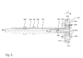
- the phaser 500 is attached via a first screw 562 in the axial extension of the central axis 588.
- the central axis passes both through the camshaft adjuster 500 and through the camshaft 582, which is designed as a double-guided camshaft, ie as a double camshaft.
- the phaser 500 has three different screw types 562, 564, 566.
- the stator housing 508 is trough-shaped and receives its own plate 510 in its trough-like interior.
- the screws of type 564 and 566 are alternately arranged in the stator vanes 528, 530, 532, 534, 536.
- the camshaft phaser 500 has six stator vanes 528, 530, 532, 534, 536. Thus, three screws of the 564 type and three 566 screws of the 566 type are alternately threaded in the camshaft adjuster 500 at a common radius. As the bolts 566 reach into the mounting flange 598, the bolts 564 hold the phaser 500 together. Around one of the screws 562 around oil guide channels are arranged. All screws 562, 564, 566 are in the design after FIG. 7 aligned in the same direction parallel to the central axis 588.
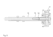
- the screws 764, 766 may be disposed on a separate ring 722, 724.
- the screws are 766 in a specially provided for them free cut space 804, which is located in each case closer to the center 720 of the camshaft adjuster 700.
- the stator blades 728, 730, 732, 734 have special recesses.
- the bolts 766 attach the stator 702 of the camshaft phaser 700 to the annular mounting flange 798 of one of the two camshafts 784, 786 of the camshaft configured as a double camshaft 782.
- the outer camshaft 786 is flared at one end to form the ring 798.
Applications Claiming Priority (1)
| Application Number | Priority Date | Filing Date | Title |
|---|---|---|---|
| DE102010033296A DE102010033296A1 (de) | 2010-08-04 | 2010-08-04 | Nockenwellenversteller, insbesondere mit Nockenwelle |
Publications (2)
| Publication Number | Publication Date |
|---|---|
| EP2415979A1 true EP2415979A1 (fr) | 2012-02-08 |
| EP2415979B1 EP2415979B1 (fr) | 2018-11-28 |
Family
ID=44675367
Family Applications (1)
| Application Number | Title | Priority Date | Filing Date |
|---|---|---|---|
| EP11169788.4A Not-in-force EP2415979B1 (fr) | 2010-08-04 | 2011-06-14 | Déphaseur d'arbre à cames |
Country Status (5)
| Country | Link |
|---|---|
| US (1) | US8677960B2 (fr) |
| EP (1) | EP2415979B1 (fr) |
| JP (1) | JP2012041922A (fr) |
| CN (1) | CN102373981B (fr) |
| DE (1) | DE102010033296A1 (fr) |
Cited By (2)
| Publication number | Priority date | Publication date | Assignee | Title |
|---|---|---|---|---|
| EP2674582A1 (fr) * | 2012-06-14 | 2013-12-18 | Volkswagen Aktiengesellschaft | Système de réglage d'arbres à cames |
| WO2015180925A3 (fr) * | 2014-05-27 | 2016-01-21 | Thyssenkrupp Presta Teccenter Ag | Arbre à cames variable à transfert d'huile amélioré entre l'arbre intérieur et l'arbre extérieur |
Families Citing this family (12)
| Publication number | Priority date | Publication date | Assignee | Title |
|---|---|---|---|---|
| DE102012208496B4 (de) | 2012-05-22 | 2013-12-05 | Schaeffler Technologies AG & Co. KG | Nockenwellenverstelleinrichtung |
| CN103410581A (zh) * | 2013-07-05 | 2013-11-27 | 广西玉柴机器股份有限公司 | 内燃机凸轮轴 |
| DE102015113356A1 (de) * | 2015-08-13 | 2017-02-16 | Thyssenkrupp Ag | Verstellbare Nockenwelle mit einem Phasenteller |
| JP6443294B2 (ja) * | 2015-10-15 | 2018-12-26 | 株式会社デンソー | バルブタイミング調整装置 |
| DE102018113977A1 (de) * | 2018-06-12 | 2019-12-12 | ECO Holding 1 GmbH | Nockenwelleneinheit und Verfahren zur Herstellung einer Nockenwelleneinheit |
| US11193399B2 (en) | 2018-11-27 | 2021-12-07 | Borgwarner, Inc. | Variable camshaft timing assembly |
| US10954829B2 (en) | 2018-12-19 | 2021-03-23 | Borgwarner, Inc. | Oldham flexplate for concentric camshafts controlled by variable camshaft timing |
| CN111485969A (zh) * | 2019-01-28 | 2020-08-04 | 舍弗勒技术股份两合公司 | 凸轮轴相位调节器 |
| US10815844B2 (en) * | 2019-03-26 | 2020-10-27 | Schaeffler Technologies AG & Co. KG | Camshaft phaser with pin |
| US10711659B1 (en) * | 2019-03-26 | 2020-07-14 | Schaeffler Technologies AG & Co. KG | Drive adapter for concentric camshaft assembly |
| US11280228B2 (en) | 2020-07-07 | 2022-03-22 | Borgwarner, Inc. | Variable camshaft timing assembly |
| US11852054B2 (en) | 2021-09-17 | 2023-12-26 | Borgwarner Inc. | Variable camshaft timing system |
Citations (27)
| Publication number | Priority date | Publication date | Assignee | Title |
|---|---|---|---|---|
| US2911956A (en) | 1959-01-07 | 1959-11-10 | Bryant Grinder Corp | Shaft positioner |
| US4332222A (en) | 1978-05-20 | 1982-06-01 | Volkswagenwerk Aktiengesellschaft | Camshaft for an internal combustion engine |
| DE3624827A1 (de) | 1986-07-23 | 1988-02-04 | Sueddeutsche Kolbenbolzenfabri | Verstelleinrichtung fuer eine nockenwelle zum steuern der gasein- und auslassventile von verbrennungsmotoren |
| EP0397540A1 (fr) | 1989-03-17 | 1990-11-14 | Regie Nationale Des Usines Renault | Arbre à cames pour moteur à distribution variable |
| WO1992012333A1 (fr) | 1991-01-12 | 1992-07-23 | Dr.Ing.H.C.F. Porsche Aktiengesellschaft | Dispositif pour l'actionnement des soupapes d'un moteur alternatif |
| US5233948A (en) | 1992-12-10 | 1993-08-10 | Ford Motor Company | Variable cycle engine |
| US5235939A (en) | 1992-11-05 | 1993-08-17 | Ford Motor Company | Automotive engine torsional pulse enhancer |
| DE4332868A1 (de) | 1993-09-27 | 1995-03-30 | Bayerische Motoren Werke Ag | Nockenwelle mit winkelverstellbaren Steuernocken, insbesondere für Ein- und Auslaß-Ventile einer Brennkraftmaschine |
| US5505168A (en) * | 1994-02-25 | 1996-04-09 | Osaka Fuji Kogyo Kabushiki Kaisha | Variable lift height valve driving device |
| JPH11173120A (ja) | 1997-12-08 | 1999-06-29 | Mitsubishi Motors Corp | 内燃機関の可変動弁装置 |
| US6076492A (en) | 1998-03-27 | 2000-06-20 | Yamaha Hatsudoki Kabushiki Kaisha | Cylinder head for variable valve timing |
| DE19914909A1 (de) | 1999-04-01 | 2000-10-05 | Bayerische Motoren Werke Ag | Nockenwelle für eine Viertakt-Brennkraftmaschine |
| WO2001012996A1 (fr) | 1999-08-17 | 2001-02-22 | Esko Raikamo | Unite d'alimentation servant a positionner des valves, ou d'autres dispositifs semblables, dans la position desiree |
| US6253719B1 (en) | 1999-02-18 | 2001-07-03 | Mechadyne Plc | Variable phase mechanism |
| DE10102767A1 (de) | 2001-01-23 | 2002-07-25 | Volkswagen Ag | Steuertrieb für Ventile einer Brennkraftmaschine |
| EP1234954A2 (fr) | 2000-11-18 | 2002-08-28 | Mechadyne PLC | Variateur de phase |
| EP1347154A2 (fr) | 2002-03-20 | 2003-09-24 | Hydraulik-Ring Gmbh | Contrôleur de levée de soupapes d'un moteur à combustion interne |
| DE102004023451A1 (de) | 2003-05-16 | 2004-12-09 | General Motors Corp., Detroit | Direkt wirkender differenzieller zweistufiger Ventiltrieb |
| WO2005040562A1 (fr) | 2003-10-25 | 2005-05-06 | Audi Ag | Mecanisme de distribution de moteur a combustion interne comprenant au moins un arbre a cames |
| DE10346446A1 (de) | 2003-10-07 | 2005-05-12 | Daimler Chrysler Ag | Nockenwellenversteller für eine Brennkraftmaschine mit Hydraulikmittelführungen |
| DE10346448A1 (de) | 2003-10-07 | 2005-06-09 | Daimlerchrysler Ag | Nockenwellenversteller für eine Brennkraftmaschine |
| DE102005014680A1 (de) | 2005-02-03 | 2006-08-10 | Mahle International Gmbh | Nockenwelle mit gegeneinander verdrehbaren Nocken für insbesondere Kraftfahrzeuge |
| EP1696107A1 (fr) | 2005-02-23 | 2006-08-30 | Mechadyne plc | Système d'arbre à cames |
| GB2444943A (en) * | 2006-12-19 | 2008-06-25 | Mechadyne Plc | Camshaft and phaser assembly |
| DE102008019746A1 (de) * | 2008-04-19 | 2009-10-22 | Schaeffler Kg | Vorrichtung zur variablen Einstellung der Steuerzeiten von Gaswechselventilen einer Brennkraftmaschine |
| DE102008023098A1 (de) * | 2008-05-09 | 2009-12-17 | Hydraulik-Ring Gmbh | Doppelter Nockenwellenversteller in Schichtaufbau |
| DE102010005607A1 (de) * | 2009-01-28 | 2010-07-29 | Schaeffler Technologies Gmbh & Co. Kg | Nockenwellen-Phasenversteller für konzentrische Nockenwellen |
Family Cites Families (11)
| Publication number | Priority date | Publication date | Assignee | Title |
|---|---|---|---|---|
| DE102004024222A1 (de) | 2003-08-15 | 2005-03-10 | Ina Schaeffler Kg | Brennkraftmaschine mit einer hydraulischen Vorrichtung zur Drehwinkelverstellung einer Nockenwelle gegenüber einer Kurbelwelle |
| US7762225B2 (en) | 2003-10-25 | 2010-07-27 | Audi Ag | Valve train of an internal combustion engine comprising at least one camshaft |
| GB2413168A (en) | 2004-04-13 | 2005-10-19 | Mechadyne Plc | Variable phase drive mechanism |
| DE102005040934A1 (de) | 2005-02-03 | 2006-08-17 | Mahle International Gmbh | Verstellbare Nockenwelle, insbesondere für Verbrennungsmotoren von Kraftfahrzeugen, mit einer hydraulischen Stelleinrichtung |
| GB0505497D0 (en) | 2005-03-18 | 2005-04-20 | Mechadyne Plc | Camshaft to phaser coupling |
| EP1754913B2 (fr) | 2005-08-16 | 2013-05-29 | Mahle International GmbH | Arbre à cames réglable |
| DE102006028611B4 (de) | 2006-06-22 | 2014-12-31 | Mahle International Gmbh | Verstellbare Nockenwelle |
| US7841311B2 (en) * | 2008-01-04 | 2010-11-30 | Hilite International Inc. | Variable valve timing device |
| DE102008033230B4 (de) | 2008-01-04 | 2010-05-27 | Hydraulik-Ring Gmbh | Doppelter Nockenwellenversteller in Schichtaufbau |
| US7789054B2 (en) | 2008-03-10 | 2010-09-07 | Gm Global Technology Operations, Inc. | Twin cam phaser for dual independent cam phasing |
| DE102008019747A1 (de) * | 2008-04-19 | 2009-10-22 | Schaeffler Kg | Vorrichtung zur variablen Einstellung der Steuerzeiten von Gaswechselventilen einer Brennkraftmaschine |
-
2010
- 2010-08-04 DE DE102010033296A patent/DE102010033296A1/de not_active Withdrawn
-
2011
- 2011-06-14 EP EP11169788.4A patent/EP2415979B1/fr not_active Not-in-force
- 2011-08-03 US US13/136,570 patent/US8677960B2/en not_active Expired - Fee Related
- 2011-08-03 JP JP2011169933A patent/JP2012041922A/ja active Pending
- 2011-08-04 CN CN201110230677.0A patent/CN102373981B/zh not_active Expired - Fee Related
Patent Citations (28)
| Publication number | Priority date | Publication date | Assignee | Title |
|---|---|---|---|---|
| US2911956A (en) | 1959-01-07 | 1959-11-10 | Bryant Grinder Corp | Shaft positioner |
| US4332222A (en) | 1978-05-20 | 1982-06-01 | Volkswagenwerk Aktiengesellschaft | Camshaft for an internal combustion engine |
| DE3624827A1 (de) | 1986-07-23 | 1988-02-04 | Sueddeutsche Kolbenbolzenfabri | Verstelleinrichtung fuer eine nockenwelle zum steuern der gasein- und auslassventile von verbrennungsmotoren |
| EP0397540A1 (fr) | 1989-03-17 | 1990-11-14 | Regie Nationale Des Usines Renault | Arbre à cames pour moteur à distribution variable |
| WO1992012333A1 (fr) | 1991-01-12 | 1992-07-23 | Dr.Ing.H.C.F. Porsche Aktiengesellschaft | Dispositif pour l'actionnement des soupapes d'un moteur alternatif |
| US5235939A (en) | 1992-11-05 | 1993-08-17 | Ford Motor Company | Automotive engine torsional pulse enhancer |
| US5233948A (en) | 1992-12-10 | 1993-08-10 | Ford Motor Company | Variable cycle engine |
| DE4332868A1 (de) | 1993-09-27 | 1995-03-30 | Bayerische Motoren Werke Ag | Nockenwelle mit winkelverstellbaren Steuernocken, insbesondere für Ein- und Auslaß-Ventile einer Brennkraftmaschine |
| US5505168A (en) * | 1994-02-25 | 1996-04-09 | Osaka Fuji Kogyo Kabushiki Kaisha | Variable lift height valve driving device |
| JPH11173120A (ja) | 1997-12-08 | 1999-06-29 | Mitsubishi Motors Corp | 内燃機関の可変動弁装置 |
| US6076492A (en) | 1998-03-27 | 2000-06-20 | Yamaha Hatsudoki Kabushiki Kaisha | Cylinder head for variable valve timing |
| US6253719B1 (en) | 1999-02-18 | 2001-07-03 | Mechadyne Plc | Variable phase mechanism |
| DE19914909A1 (de) | 1999-04-01 | 2000-10-05 | Bayerische Motoren Werke Ag | Nockenwelle für eine Viertakt-Brennkraftmaschine |
| WO2001012996A1 (fr) | 1999-08-17 | 2001-02-22 | Esko Raikamo | Unite d'alimentation servant a positionner des valves, ou d'autres dispositifs semblables, dans la position desiree |
| US6725817B2 (en) | 2000-11-18 | 2004-04-27 | Mechadyne Plc | Variable phase drive mechanism |
| EP1234954A2 (fr) | 2000-11-18 | 2002-08-28 | Mechadyne PLC | Variateur de phase |
| DE10102767A1 (de) | 2001-01-23 | 2002-07-25 | Volkswagen Ag | Steuertrieb für Ventile einer Brennkraftmaschine |
| EP1347154A2 (fr) | 2002-03-20 | 2003-09-24 | Hydraulik-Ring Gmbh | Contrôleur de levée de soupapes d'un moteur à combustion interne |
| DE102004023451A1 (de) | 2003-05-16 | 2004-12-09 | General Motors Corp., Detroit | Direkt wirkender differenzieller zweistufiger Ventiltrieb |
| DE10346446A1 (de) | 2003-10-07 | 2005-05-12 | Daimler Chrysler Ag | Nockenwellenversteller für eine Brennkraftmaschine mit Hydraulikmittelführungen |
| DE10346448A1 (de) | 2003-10-07 | 2005-06-09 | Daimlerchrysler Ag | Nockenwellenversteller für eine Brennkraftmaschine |
| WO2005040562A1 (fr) | 2003-10-25 | 2005-05-06 | Audi Ag | Mecanisme de distribution de moteur a combustion interne comprenant au moins un arbre a cames |
| DE102005014680A1 (de) | 2005-02-03 | 2006-08-10 | Mahle International Gmbh | Nockenwelle mit gegeneinander verdrehbaren Nocken für insbesondere Kraftfahrzeuge |
| EP1696107A1 (fr) | 2005-02-23 | 2006-08-30 | Mechadyne plc | Système d'arbre à cames |
| GB2444943A (en) * | 2006-12-19 | 2008-06-25 | Mechadyne Plc | Camshaft and phaser assembly |
| DE102008019746A1 (de) * | 2008-04-19 | 2009-10-22 | Schaeffler Kg | Vorrichtung zur variablen Einstellung der Steuerzeiten von Gaswechselventilen einer Brennkraftmaschine |
| DE102008023098A1 (de) * | 2008-05-09 | 2009-12-17 | Hydraulik-Ring Gmbh | Doppelter Nockenwellenversteller in Schichtaufbau |
| DE102010005607A1 (de) * | 2009-01-28 | 2010-07-29 | Schaeffler Technologies Gmbh & Co. Kg | Nockenwellen-Phasenversteller für konzentrische Nockenwellen |
Cited By (3)
| Publication number | Priority date | Publication date | Assignee | Title |
|---|---|---|---|---|
| EP2674582A1 (fr) * | 2012-06-14 | 2013-12-18 | Volkswagen Aktiengesellschaft | Système de réglage d'arbres à cames |
| WO2015180925A3 (fr) * | 2014-05-27 | 2016-01-21 | Thyssenkrupp Presta Teccenter Ag | Arbre à cames variable à transfert d'huile amélioré entre l'arbre intérieur et l'arbre extérieur |
| US10208632B2 (en) | 2014-05-27 | 2019-02-19 | Thyssenkrupp Presta Teccenter Ag | Variable valve timing camshaft with improved oil transfer between inner and outer shafts |
Also Published As
| Publication number | Publication date |
|---|---|
| US8677960B2 (en) | 2014-03-25 |
| JP2012041922A (ja) | 2012-03-01 |
| US20120031358A1 (en) | 2012-02-09 |
| CN102373981B (zh) | 2016-02-10 |
| DE102010033296A1 (de) | 2012-02-09 |
| EP2415979B1 (fr) | 2018-11-28 |
| CN102373981A (zh) | 2012-03-14 |
Similar Documents
| Publication | Publication Date | Title |
|---|---|---|
| EP2415979B1 (fr) | Déphaseur d'arbre à cames | |
| DE60201949T2 (de) | Nockenwellenverstellanordnung für eine Vierzylinderbrennkraftmaschine | |
| EP1832723B1 (fr) | Commande de soupape pour régler la levée des soupapes dans un moteur à combustion interne | |
| DE102009050779A1 (de) | Schwenkmotornockenwellenversteller mit einer Reibscheibe und Montageverfahren | |
| EP2486248B1 (fr) | Agencement d'arbre à cames | |
| DE102008033230A1 (de) | Doppelter Nockenwellenversteller in Schichtaufbau | |
| WO2006005406A1 (fr) | Regulateur d'arbre a cames a commande electrique | |
| DE102010050606A1 (de) | Rotor für einen Nockenwellenversteller sowie Nockenwellenversteller | |
| EP2500532A1 (fr) | Déphaseur à moteur oscillant | |
| DE102006007651A1 (de) | Nockenwellenversteller mit einem Überlagerungsgetriebe | |
| WO2007093479A1 (fr) | Dispositif d'ajustement d'arbre a cames dote d'une transmission a superposition | |
| WO2016110281A1 (fr) | Liaison d'un régleur d'arbre à cames à un double arbre à cames | |
| DE10020119A1 (de) | Vorrichtung zur unabhängigen hydraulischen Verstellung der Phasen- und Axiallage einer Nockenwelle | |
| EP2118455B1 (fr) | Dispositif combiné de verrouillage et de limitation d'angle de rotation d'un variateur d'arbre à cames | |
| DE102004026863A1 (de) | Nockenwellerversteller | |
| DE102008023066B4 (de) | Nockenwellenverstellung mit trockener Lauffläche | |
| DE10353588A1 (de) | Nockenverstelleinrichtung und Steuerglied hierfür | |
| DE102008023098A1 (de) | Doppelter Nockenwellenversteller in Schichtaufbau | |
| DE102010060263A1 (de) | Schwenkmotorversteller | |
| EP1989404A1 (fr) | Dispositif d'ajustement variable des instants d'activation des soupapes d'un moteur a combustion interne | |
| DE10161457B4 (de) | Variabel gesteuerte Nockenwellenanordnung mit doppelter Ölzufuhr | |
| DE102004019190A1 (de) | Nockenwellenversteller | |
| EP1783331B1 (fr) | Système comprenant un arbre à cames d'admission, un arbre à cames d'échappement et un variateur de phase, et utilisation de ce système | |
| WO2015149763A2 (fr) | Déphaseur d'arbre à cames | |
| WO2011042392A1 (fr) | Ensemble arbre à cames |
Legal Events
| Date | Code | Title | Description |
|---|---|---|---|
| AK | Designated contracting states |
Kind code of ref document: A1 Designated state(s): AL AT BE BG CH CY CZ DE DK EE ES FI FR GB GR HR HU IE IS IT LI LT LU LV MC MK MT NL NO PL PT RO RS SE SI SK SM TR |
|
| AX | Request for extension of the european patent |
Extension state: BA ME |
|
| PUAI | Public reference made under article 153(3) epc to a published international application that has entered the european phase |
Free format text: ORIGINAL CODE: 0009012 |
|
| RAP1 | Party data changed (applicant data changed or rights of an application transferred) |
Owner name: HILITE GERMANY GMBH |
|
| 17P | Request for examination filed |
Effective date: 20120224 |
|
| 17Q | First examination report despatched |
Effective date: 20160802 |
|
| STAA | Information on the status of an ep patent application or granted ep patent |
Free format text: STATUS: EXAMINATION IS IN PROGRESS |
|
| GRAP | Despatch of communication of intention to grant a patent |
Free format text: ORIGINAL CODE: EPIDOSNIGR1 |
|
| STAA | Information on the status of an ep patent application or granted ep patent |
Free format text: STATUS: GRANT OF PATENT IS INTENDED |
|
| GRAS | Grant fee paid |
Free format text: ORIGINAL CODE: EPIDOSNIGR3 |
|
| INTG | Intention to grant announced |
Effective date: 20180731 |
|
| GRAA | (expected) grant |
Free format text: ORIGINAL CODE: 0009210 |
|
| STAA | Information on the status of an ep patent application or granted ep patent |
Free format text: STATUS: THE PATENT HAS BEEN GRANTED |
|
| AK | Designated contracting states |
Kind code of ref document: B1 Designated state(s): AL AT BE BG CH CY CZ DE DK EE ES FI FR GB GR HR HU IE IS IT LI LT LU LV MC MK MT NL NO PL PT RO RS SE SI SK SM TR |
|
| REG | Reference to a national code |
Ref country code: GB Ref legal event code: FG4D Free format text: NOT ENGLISH |
|
| REG | Reference to a national code |
Ref country code: CH Ref legal event code: EP |
|
| REG | Reference to a national code |
Ref country code: AT Ref legal event code: REF Ref document number: 1070501 Country of ref document: AT Kind code of ref document: T Effective date: 20181215 |
|
| REG | Reference to a national code |
Ref country code: DE Ref legal event code: R096 Ref document number: 502011015069 Country of ref document: DE |
|
| REG | Reference to a national code |
Ref country code: IE Ref legal event code: FG4D Free format text: LANGUAGE OF EP DOCUMENT: GERMAN |
|
| REG | Reference to a national code |
Ref country code: NL Ref legal event code: MP Effective date: 20181128 |
|
| REG | Reference to a national code |
Ref country code: LT Ref legal event code: MG4D |
|
| PG25 | Lapsed in a contracting state [announced via postgrant information from national office to epo] |
Ref country code: HR Free format text: LAPSE BECAUSE OF FAILURE TO SUBMIT A TRANSLATION OF THE DESCRIPTION OR TO PAY THE FEE WITHIN THE PRESCRIBED TIME-LIMIT Effective date: 20181128 Ref country code: NO Free format text: LAPSE BECAUSE OF FAILURE TO SUBMIT A TRANSLATION OF THE DESCRIPTION OR TO PAY THE FEE WITHIN THE PRESCRIBED TIME-LIMIT Effective date: 20190228 Ref country code: LV Free format text: LAPSE BECAUSE OF FAILURE TO SUBMIT A TRANSLATION OF THE DESCRIPTION OR TO PAY THE FEE WITHIN THE PRESCRIBED TIME-LIMIT Effective date: 20181128 Ref country code: FI Free format text: LAPSE BECAUSE OF FAILURE TO SUBMIT A TRANSLATION OF THE DESCRIPTION OR TO PAY THE FEE WITHIN THE PRESCRIBED TIME-LIMIT Effective date: 20181128 Ref country code: IS Free format text: LAPSE BECAUSE OF FAILURE TO SUBMIT A TRANSLATION OF THE DESCRIPTION OR TO PAY THE FEE WITHIN THE PRESCRIBED TIME-LIMIT Effective date: 20190328 Ref country code: BG Free format text: LAPSE BECAUSE OF FAILURE TO SUBMIT A TRANSLATION OF THE DESCRIPTION OR TO PAY THE FEE WITHIN THE PRESCRIBED TIME-LIMIT Effective date: 20190228 Ref country code: LT Free format text: LAPSE BECAUSE OF FAILURE TO SUBMIT A TRANSLATION OF THE DESCRIPTION OR TO PAY THE FEE WITHIN THE PRESCRIBED TIME-LIMIT Effective date: 20181128 Ref country code: ES Free format text: LAPSE BECAUSE OF FAILURE TO SUBMIT A TRANSLATION OF THE DESCRIPTION OR TO PAY THE FEE WITHIN THE PRESCRIBED TIME-LIMIT Effective date: 20181128 |
|
| PG25 | Lapsed in a contracting state [announced via postgrant information from national office to epo] |
Ref country code: AL Free format text: LAPSE BECAUSE OF FAILURE TO SUBMIT A TRANSLATION OF THE DESCRIPTION OR TO PAY THE FEE WITHIN THE PRESCRIBED TIME-LIMIT Effective date: 20181128 Ref country code: PT Free format text: LAPSE BECAUSE OF FAILURE TO SUBMIT A TRANSLATION OF THE DESCRIPTION OR TO PAY THE FEE WITHIN THE PRESCRIBED TIME-LIMIT Effective date: 20190328 Ref country code: RS Free format text: LAPSE BECAUSE OF FAILURE TO SUBMIT A TRANSLATION OF THE DESCRIPTION OR TO PAY THE FEE WITHIN THE PRESCRIBED TIME-LIMIT Effective date: 20181128 Ref country code: SE Free format text: LAPSE BECAUSE OF FAILURE TO SUBMIT A TRANSLATION OF THE DESCRIPTION OR TO PAY THE FEE WITHIN THE PRESCRIBED TIME-LIMIT Effective date: 20181128 Ref country code: GR Free format text: LAPSE BECAUSE OF FAILURE TO SUBMIT A TRANSLATION OF THE DESCRIPTION OR TO PAY THE FEE WITHIN THE PRESCRIBED TIME-LIMIT Effective date: 20190301 |
|
| PG25 | Lapsed in a contracting state [announced via postgrant information from national office to epo] |
Ref country code: NL Free format text: LAPSE BECAUSE OF FAILURE TO SUBMIT A TRANSLATION OF THE DESCRIPTION OR TO PAY THE FEE WITHIN THE PRESCRIBED TIME-LIMIT Effective date: 20181128 |
|
| PG25 | Lapsed in a contracting state [announced via postgrant information from national office to epo] |
Ref country code: PL Free format text: LAPSE BECAUSE OF FAILURE TO SUBMIT A TRANSLATION OF THE DESCRIPTION OR TO PAY THE FEE WITHIN THE PRESCRIBED TIME-LIMIT Effective date: 20181128 Ref country code: CZ Free format text: LAPSE BECAUSE OF FAILURE TO SUBMIT A TRANSLATION OF THE DESCRIPTION OR TO PAY THE FEE WITHIN THE PRESCRIBED TIME-LIMIT Effective date: 20181128 Ref country code: IT Free format text: LAPSE BECAUSE OF FAILURE TO SUBMIT A TRANSLATION OF THE DESCRIPTION OR TO PAY THE FEE WITHIN THE PRESCRIBED TIME-LIMIT Effective date: 20181128 Ref country code: DK Free format text: LAPSE BECAUSE OF FAILURE TO SUBMIT A TRANSLATION OF THE DESCRIPTION OR TO PAY THE FEE WITHIN THE PRESCRIBED TIME-LIMIT Effective date: 20181128 |
|
| REG | Reference to a national code |
Ref country code: DE Ref legal event code: R097 Ref document number: 502011015069 Country of ref document: DE |
|
| PG25 | Lapsed in a contracting state [announced via postgrant information from national office to epo] |
Ref country code: SM Free format text: LAPSE BECAUSE OF FAILURE TO SUBMIT A TRANSLATION OF THE DESCRIPTION OR TO PAY THE FEE WITHIN THE PRESCRIBED TIME-LIMIT Effective date: 20181128 Ref country code: EE Free format text: LAPSE BECAUSE OF FAILURE TO SUBMIT A TRANSLATION OF THE DESCRIPTION OR TO PAY THE FEE WITHIN THE PRESCRIBED TIME-LIMIT Effective date: 20181128 Ref country code: SK Free format text: LAPSE BECAUSE OF FAILURE TO SUBMIT A TRANSLATION OF THE DESCRIPTION OR TO PAY THE FEE WITHIN THE PRESCRIBED TIME-LIMIT Effective date: 20181128 Ref country code: RO Free format text: LAPSE BECAUSE OF FAILURE TO SUBMIT A TRANSLATION OF THE DESCRIPTION OR TO PAY THE FEE WITHIN THE PRESCRIBED TIME-LIMIT Effective date: 20181128 |
|
| PLBE | No opposition filed within time limit |
Free format text: ORIGINAL CODE: 0009261 |
|
| STAA | Information on the status of an ep patent application or granted ep patent |
Free format text: STATUS: NO OPPOSITION FILED WITHIN TIME LIMIT |
|
| PG25 | Lapsed in a contracting state [announced via postgrant information from national office to epo] |
Ref country code: SI Free format text: LAPSE BECAUSE OF FAILURE TO SUBMIT A TRANSLATION OF THE DESCRIPTION OR TO PAY THE FEE WITHIN THE PRESCRIBED TIME-LIMIT Effective date: 20181128 |
|
| 26N | No opposition filed |
Effective date: 20190829 |
|
| PG25 | Lapsed in a contracting state [announced via postgrant information from national office to epo] |
Ref country code: MC Free format text: LAPSE BECAUSE OF FAILURE TO SUBMIT A TRANSLATION OF THE DESCRIPTION OR TO PAY THE FEE WITHIN THE PRESCRIBED TIME-LIMIT Effective date: 20181128 |
|
| REG | Reference to a national code |
Ref country code: CH Ref legal event code: PL |
|
| GBPC | Gb: european patent ceased through non-payment of renewal fee |
Effective date: 20190614 |
|
| REG | Reference to a national code |
Ref country code: BE Ref legal event code: MM Effective date: 20190630 |
|
| PG25 | Lapsed in a contracting state [announced via postgrant information from national office to epo] |
Ref country code: TR Free format text: LAPSE BECAUSE OF FAILURE TO SUBMIT A TRANSLATION OF THE DESCRIPTION OR TO PAY THE FEE WITHIN THE PRESCRIBED TIME-LIMIT Effective date: 20181128 |
|
| PG25 | Lapsed in a contracting state [announced via postgrant information from national office to epo] |
Ref country code: GB Free format text: LAPSE BECAUSE OF NON-PAYMENT OF DUE FEES Effective date: 20190614 Ref country code: IE Free format text: LAPSE BECAUSE OF NON-PAYMENT OF DUE FEES Effective date: 20190614 |
|
| PG25 | Lapsed in a contracting state [announced via postgrant information from national office to epo] |
Ref country code: LU Free format text: LAPSE BECAUSE OF NON-PAYMENT OF DUE FEES Effective date: 20190614 Ref country code: BE Free format text: LAPSE BECAUSE OF NON-PAYMENT OF DUE FEES Effective date: 20190630 Ref country code: LI Free format text: LAPSE BECAUSE OF NON-PAYMENT OF DUE FEES Effective date: 20190630 Ref country code: CH Free format text: LAPSE BECAUSE OF NON-PAYMENT OF DUE FEES Effective date: 20190630 |
|
| REG | Reference to a national code |
Ref country code: AT Ref legal event code: MM01 Ref document number: 1070501 Country of ref document: AT Kind code of ref document: T Effective date: 20190614 |
|
| PG25 | Lapsed in a contracting state [announced via postgrant information from national office to epo] |
Ref country code: AT Free format text: LAPSE BECAUSE OF NON-PAYMENT OF DUE FEES Effective date: 20190614 |
|
| PG25 | Lapsed in a contracting state [announced via postgrant information from national office to epo] |
Ref country code: CY Free format text: LAPSE BECAUSE OF FAILURE TO SUBMIT A TRANSLATION OF THE DESCRIPTION OR TO PAY THE FEE WITHIN THE PRESCRIBED TIME-LIMIT Effective date: 20181128 |
|
| PG25 | Lapsed in a contracting state [announced via postgrant information from national office to epo] |
Ref country code: MT Free format text: LAPSE BECAUSE OF FAILURE TO SUBMIT A TRANSLATION OF THE DESCRIPTION OR TO PAY THE FEE WITHIN THE PRESCRIBED TIME-LIMIT Effective date: 20181128 Ref country code: HU Free format text: LAPSE BECAUSE OF FAILURE TO SUBMIT A TRANSLATION OF THE DESCRIPTION OR TO PAY THE FEE WITHIN THE PRESCRIBED TIME-LIMIT; INVALID AB INITIO Effective date: 20110614 |
|
| PGFP | Annual fee paid to national office [announced via postgrant information from national office to epo] |
Ref country code: FR Payment date: 20210622 Year of fee payment: 11 Ref country code: DE Payment date: 20210618 Year of fee payment: 11 |
|
| PG25 | Lapsed in a contracting state [announced via postgrant information from national office to epo] |
Ref country code: MK Free format text: LAPSE BECAUSE OF FAILURE TO SUBMIT A TRANSLATION OF THE DESCRIPTION OR TO PAY THE FEE WITHIN THE PRESCRIBED TIME-LIMIT Effective date: 20181128 |
|
| REG | Reference to a national code |
Ref country code: DE Ref legal event code: R119 Ref document number: 502011015069 Country of ref document: DE |
|
| PG25 | Lapsed in a contracting state [announced via postgrant information from national office to epo] |
Ref country code: FR Free format text: LAPSE BECAUSE OF NON-PAYMENT OF DUE FEES Effective date: 20220630 |
|
| PG25 | Lapsed in a contracting state [announced via postgrant information from national office to epo] |
Ref country code: DE Free format text: LAPSE BECAUSE OF NON-PAYMENT OF DUE FEES Effective date: 20230103 |