EP1696107A1 - Système d'arbre à cames - Google Patents
Système d'arbre à cames Download PDFInfo
- Publication number
- EP1696107A1 EP1696107A1 EP06270018A EP06270018A EP1696107A1 EP 1696107 A1 EP1696107 A1 EP 1696107A1 EP 06270018 A EP06270018 A EP 06270018A EP 06270018 A EP06270018 A EP 06270018A EP 1696107 A1 EP1696107 A1 EP 1696107A1
- Authority
- EP
- European Patent Office
- Prior art keywords
- inner shaft
- outer tube
- combination
- camshaft
- phaser
- Prior art date
- Legal status (The legal status is an assumption and is not a legal conclusion. Google has not performed a legal analysis and makes no representation as to the accuracy of the status listed.)
- Granted
Links
- RDYMFSUJUZBWLH-UHFFFAOYSA-N endosulfan Chemical compound C12COS(=O)OCC2C2(Cl)C(Cl)=C(Cl)C1(Cl)C2(Cl)Cl RDYMFSUJUZBWLH-UHFFFAOYSA-N 0.000 claims description 34
- 239000002131 composite material Substances 0.000 claims description 3
- 230000008878 coupling Effects 0.000 description 3
- 238000010168 coupling process Methods 0.000 description 3
- 238000005859 coupling reaction Methods 0.000 description 3
- 239000012530 fluid Substances 0.000 description 2
- 238000004519 manufacturing process Methods 0.000 description 2
- 230000007246 mechanism Effects 0.000 description 2
- 238000000034 method Methods 0.000 description 2
- 230000004044 response Effects 0.000 description 2
- 230000000712 assembly Effects 0.000 description 1
- 238000000429 assembly Methods 0.000 description 1
- 238000005452 bending Methods 0.000 description 1
- 230000008859 change Effects 0.000 description 1
- 238000006073 displacement reaction Methods 0.000 description 1
- 239000000463 material Substances 0.000 description 1
- 230000010363 phase shift Effects 0.000 description 1
Images
Classifications
-
- F—MECHANICAL ENGINEERING; LIGHTING; HEATING; WEAPONS; BLASTING
- F01—MACHINES OR ENGINES IN GENERAL; ENGINE PLANTS IN GENERAL; STEAM ENGINES
- F01L—CYCLICALLY OPERATING VALVES FOR MACHINES OR ENGINES
- F01L1/00—Valve-gear or valve arrangements, e.g. lift-valve gear
- F01L1/34—Valve-gear or valve arrangements, e.g. lift-valve gear characterised by the provision of means for changing the timing of the valves without changing the duration of opening and without affecting the magnitude of the valve lift
- F01L1/344—Valve-gear or valve arrangements, e.g. lift-valve gear characterised by the provision of means for changing the timing of the valves without changing the duration of opening and without affecting the magnitude of the valve lift changing the angular relationship between crankshaft and camshaft, e.g. using helicoidal gear
- F01L1/34413—Valve-gear or valve arrangements, e.g. lift-valve gear characterised by the provision of means for changing the timing of the valves without changing the duration of opening and without affecting the magnitude of the valve lift changing the angular relationship between crankshaft and camshaft, e.g. using helicoidal gear using composite camshafts, e.g. with cams being able to move relative to the camshaft
-
- F—MECHANICAL ENGINEERING; LIGHTING; HEATING; WEAPONS; BLASTING
- F01—MACHINES OR ENGINES IN GENERAL; ENGINE PLANTS IN GENERAL; STEAM ENGINES
- F01L—CYCLICALLY OPERATING VALVES FOR MACHINES OR ENGINES
- F01L1/00—Valve-gear or valve arrangements, e.g. lift-valve gear
- F01L1/02—Valve drive
- F01L1/04—Valve drive by means of cams, camshafts, cam discs, eccentrics or the like
- F01L1/047—Camshafts
-
- F—MECHANICAL ENGINEERING; LIGHTING; HEATING; WEAPONS; BLASTING
- F01—MACHINES OR ENGINES IN GENERAL; ENGINE PLANTS IN GENERAL; STEAM ENGINES
- F01L—CYCLICALLY OPERATING VALVES FOR MACHINES OR ENGINES
- F01L1/00—Valve-gear or valve arrangements, e.g. lift-valve gear
- F01L1/34—Valve-gear or valve arrangements, e.g. lift-valve gear characterised by the provision of means for changing the timing of the valves without changing the duration of opening and without affecting the magnitude of the valve lift
- F01L1/344—Valve-gear or valve arrangements, e.g. lift-valve gear characterised by the provision of means for changing the timing of the valves without changing the duration of opening and without affecting the magnitude of the valve lift changing the angular relationship between crankshaft and camshaft, e.g. using helicoidal gear
- F01L1/3442—Valve-gear or valve arrangements, e.g. lift-valve gear characterised by the provision of means for changing the timing of the valves without changing the duration of opening and without affecting the magnitude of the valve lift changing the angular relationship between crankshaft and camshaft, e.g. using helicoidal gear using hydraulic chambers with variable volume to transmit the rotating force
-
- F—MECHANICAL ENGINEERING; LIGHTING; HEATING; WEAPONS; BLASTING
- F01—MACHINES OR ENGINES IN GENERAL; ENGINE PLANTS IN GENERAL; STEAM ENGINES
- F01L—CYCLICALLY OPERATING VALVES FOR MACHINES OR ENGINES
- F01L1/00—Valve-gear or valve arrangements, e.g. lift-valve gear
- F01L1/02—Valve drive
- F01L1/04—Valve drive by means of cams, camshafts, cam discs, eccentrics or the like
- F01L1/047—Camshafts
- F01L2001/0471—Assembled camshafts
- F01L2001/0473—Composite camshafts, e.g. with cams or cam sleeve being able to move relative to the inner camshaft or a cam adjusting rod
-
- F—MECHANICAL ENGINEERING; LIGHTING; HEATING; WEAPONS; BLASTING
- F01—MACHINES OR ENGINES IN GENERAL; ENGINE PLANTS IN GENERAL; STEAM ENGINES
- F01L—CYCLICALLY OPERATING VALVES FOR MACHINES OR ENGINES
- F01L1/00—Valve-gear or valve arrangements, e.g. lift-valve gear
- F01L1/34—Valve-gear or valve arrangements, e.g. lift-valve gear characterised by the provision of means for changing the timing of the valves without changing the duration of opening and without affecting the magnitude of the valve lift
- F01L1/344—Valve-gear or valve arrangements, e.g. lift-valve gear characterised by the provision of means for changing the timing of the valves without changing the duration of opening and without affecting the magnitude of the valve lift changing the angular relationship between crankshaft and camshaft, e.g. using helicoidal gear
- F01L1/3442—Valve-gear or valve arrangements, e.g. lift-valve gear characterised by the provision of means for changing the timing of the valves without changing the duration of opening and without affecting the magnitude of the valve lift changing the angular relationship between crankshaft and camshaft, e.g. using helicoidal gear using hydraulic chambers with variable volume to transmit the rotating force
- F01L2001/34423—Details relating to the hydraulic feeding circuit
- F01L2001/34426—Oil control valves
- F01L2001/34433—Location oil control valves
-
- F—MECHANICAL ENGINEERING; LIGHTING; HEATING; WEAPONS; BLASTING
- F01—MACHINES OR ENGINES IN GENERAL; ENGINE PLANTS IN GENERAL; STEAM ENGINES
- F01L—CYCLICALLY OPERATING VALVES FOR MACHINES OR ENGINES
- F01L1/00—Valve-gear or valve arrangements, e.g. lift-valve gear
- F01L1/34—Valve-gear or valve arrangements, e.g. lift-valve gear characterised by the provision of means for changing the timing of the valves without changing the duration of opening and without affecting the magnitude of the valve lift
- F01L1/344—Valve-gear or valve arrangements, e.g. lift-valve gear characterised by the provision of means for changing the timing of the valves without changing the duration of opening and without affecting the magnitude of the valve lift changing the angular relationship between crankshaft and camshaft, e.g. using helicoidal gear
- F01L1/3442—Valve-gear or valve arrangements, e.g. lift-valve gear characterised by the provision of means for changing the timing of the valves without changing the duration of opening and without affecting the magnitude of the valve lift changing the angular relationship between crankshaft and camshaft, e.g. using helicoidal gear using hydraulic chambers with variable volume to transmit the rotating force
- F01L2001/3445—Details relating to the hydraulic means for changing the angular relationship
- F01L2001/34453—Locking means between driving and driven members
- F01L2001/34469—Lock movement parallel to camshaft axis
-
- F—MECHANICAL ENGINEERING; LIGHTING; HEATING; WEAPONS; BLASTING
- F01—MACHINES OR ENGINES IN GENERAL; ENGINE PLANTS IN GENERAL; STEAM ENGINES
- F01L—CYCLICALLY OPERATING VALVES FOR MACHINES OR ENGINES
- F01L2250/00—Camshaft drives characterised by their transmission means
- F01L2250/02—Camshaft drives characterised by their transmission means the camshaft being driven by chains
-
- Y—GENERAL TAGGING OF NEW TECHNOLOGICAL DEVELOPMENTS; GENERAL TAGGING OF CROSS-SECTIONAL TECHNOLOGIES SPANNING OVER SEVERAL SECTIONS OF THE IPC; TECHNICAL SUBJECTS COVERED BY FORMER USPC CROSS-REFERENCE ART COLLECTIONS [XRACs] AND DIGESTS
- Y10—TECHNICAL SUBJECTS COVERED BY FORMER USPC
- Y10T—TECHNICAL SUBJECTS COVERED BY FORMER US CLASSIFICATION
- Y10T74/00—Machine element or mechanism
- Y10T74/21—Elements
- Y10T74/2173—Cranks and wrist pins
Definitions
- the present invention relates to a camshaft assembly and to a combination of a camshaft assembly with a phaser.
- the invention is particularly applicable to engines with SCP camshafts that have large support bearings and which are designed to be assembled to the engine from one end of a bearing bore in the cylinder block or cylinder head.
- Camshaft assemblies which comprise an inner shaft and an outer tube surrounding and rotatable relative to the inner shaft. Two groups of cam lobes are mounted on the outer tube, the first group of cam lobes being fast in rotation with the outer tube and the second group being rotatably mounted on the outer surface of the tube and driven by the inner shaft by way of pins that pass with clearance through circumferentially extending slots in the outer tube.
- This type of camshaft assembly is termed an SCP (Single Camshaft Phaser) camshaft because it enables the relative phase of valves operated by cam lobes on the same camshaft to be varied.
- phase change mechanism also termed a phaser
- phaser which have two concentric output members.
- the phase of the output members of the phaser can be varied by rotating them relative to one another and in some phaser designs the phase of both output members can be varied relative to the engine crankshaft.
- the conventional approach to coupling the two concentric output members of a phaser to the concentric inner shaft and outer tube of an SCP camshaft is to couple the inner shaft to the inner of the two phaser output members and the outer tube of the SCP camshaft to the outer of the two output members of the phaser. Difficulty arises in this approach in establishing a secure coupling between the outer output member of the phaser and the end of the outer tube of the SCP camshaft.
- a camshaft assembly comprising an inner shaft, an outer tube surrounding and rotatable relative to the inner shaft, and two groups of cam lobes mounted on the outer tube, the first group of cam lobes being fast in rotation with the outer tube and the second group being rotatably mounted on the outer surface of the tube and being driven by the inner shaft by way of pins that pass with clearance through circumferentially extending slots in the outer tube, characterised in that a sleeve is rotatably mounted on the outer tube, which sleeve is connected to impart drive to the inner shaft by means of a pin passing with clearance through a circumferentially extending slot in the outer tube.
- the present invention elegantly circumvents the difficulty encountered in the prior art by enabling the connections between the output members of the phaser and the SCP camshaft to be reversed.
- the outer of the phaser output members may be connected to the inner shaft of the camshaft by making use of the sleeve that is rotatable relative to the outer tube.
- US 5,441,021 describes an assembled camshaft in which the phase of cams rotatably mounted on an outer tube is varied by means of an axially displaceable inner shaft.
- Pins which project radially from the inner shaft through axially extending slots in the outer tube engage in helical grooves in the inner surface of the cams. The radial pins cause the cams to rotate relative to the outer tube in response to axial displacement of the inner shaft.
- the inner shaft is driven axially by means of a pin which engages in a sleeve slidable relative to the outer tube, the sleeve being itself moved axially in response to radial movement of centrifugal weights.
- Such a mechanism differs fundamentally from the present invention because the inner shaft is not required to transmit the torque needed for opening and closing the engine valves.
- the sleeve is a bearing sleeve which is also used to support the camshaft in a pillar block.
- the bearing sleeve of an SCP camshaft is fast in rotation with the outer tube of the camshaft but in the preferred embodiment of the present invention it is allowed to rotate about the outer tube and is connected by a pin passing with clearance through a slot in the outer tube to impart drive to the inner shaft of the camshaft.
- the camshaft outer tube may thus conveniently be driven via a fixed insert permanently joined to the front end of the outer tube which supports the camshaft phaser and contains the necessary oil passages for controlling the camshaft phaser.
- the camshaft tube can be fitted with a threaded insert which allows the phaser to be connected to it via a central fixing bolt.
- This design lends itself to having all the cam lobes that are rotatably mounted on the outer tube connected to bearing sleeves of the camshaft, as this allows a single connecting pin to rotate a group of cam lobes and bearings.
- these rotating components can be expensive to manufacture from a single piece of material, they are produced in the preferred embodiment of the invention as composites made up from a number of separately formed simple parts that are assembled to one another.
- Any SCP camshaft design must provide adequate control of the axial position of the inner drive shaft relative to the camshaft tube.
- a self retaining fastener in the bore of the camshaft outer tube is used to achieve this objective in a simple and cost effective manner.
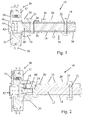
- an SCP camshaft 10 comprises an inner shaft 12 and an outer tube 14.
- Cam lobes 16 are secured for rotation with the outer tube 16.
- Sleeves 18 and 20, which act as bearing sleeves for supporting the camshaft 10 in pillar blocks in the engine, are rotatably mounted on the outer tube 14 and are fixed in rotation with the inner shaft 12 by means of pins 22 and 24 which pass with clearance through tangentially elongated slots in the outer tube 14. In this way the bearing sleeves 18 and 20 are afforded a limited degree of rotation relative to the outer tube 14.
- the sleeve 20 is formed integrally with a cam lobe 26 which rotates with the inner shaft 12.
- the sleeve 18 is formed integrally with two further cam lobes 26 that rotate with the inner shaft 12. In this way, when the inner shaft rotates relative to the outer tube 14 the phase of the cam lobes 16 is varied in relation to the phase of the cam lobes 26.
- the sleeve 20 also has a notch 21 which forms part of a sensor to determine the angular position of the inner shaft 12.
- a phaser 30 is fixed to the left hand end as viewed of the camshaft 10.
- the phaser 30 is a hydraulically operated vane-type phaser which is itself known and does not need to be described in detail in the present context.
- the phaser 30 has arcuate cavities formed in a stator 36 having sprocket teeth 38 and driven by the engine crankshaft.
- Two end plates 32 and 34 arranged on opposite sides of the stator 36, which act as output members, are connected to radial vanes that are received in the arcuate cavities to form arcuate working chambers.
- the phaser has a hub 42 that is clamped by means of a nut 46 for rotation with the output member 34.
- the hub 42 is also formed with passages 44 through which fluid is supplied to and drained from the working chambers of the phaser 30.
- a connector plug (not shown), which forms part of an engine cover, is used to connect the phaser to a control valve that controls the phasing of the engine valves. Because there are two separate hydraulic circuits, the phase of the each of the output members 32 and 34 can be controlled separately in relation to the engine crankshaft.
- the inner shaft 12 is prevented from moving to the left, as viewed in Figure 1 by abutment with the insert 40.
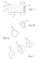
- a self retaining spring fastener 50 is inserted into the opposite end of the outer tube 14 as shown in Figure 3, the fastener itself being shown more clearly in Figures 4a and 4b.
- FIG. 2 The embodiment of Figure 2 is generally similar to that of Figure 1 and like reference numerals have been used for like components. Where components have been modified, a prime has been added to the reference numeral.
- the two embodiments differ in only two respects.
- First, the hub 42' and the insert 40' are formed separately from one another and secured to one another by means of a bolt 41.
- the cam lobes 26' are an interference fit in the bearing sleeve 18', the semi-circular cut-outs being sufficient large to allow the pin 22 to pass through unhindered.
- the sleeves 18' and the cam lobes 26' may be welded or brazed to one another or screw threaded into each other.
Applications Claiming Priority (1)
| Application Number | Priority Date | Filing Date | Title |
|---|---|---|---|
| GB0503700A GB2423565A (en) | 2005-02-23 | 2005-02-23 | Inner camshaft of SCP assembly receives drive via sleeve on outer tube |
Publications (2)
| Publication Number | Publication Date |
|---|---|
| EP1696107A1 true EP1696107A1 (fr) | 2006-08-30 |
| EP1696107B1 EP1696107B1 (fr) | 2007-08-01 |
Family
ID=34401164
Family Applications (1)
| Application Number | Title | Priority Date | Filing Date |
|---|---|---|---|
| EP06270018A Active EP1696107B1 (fr) | 2005-02-23 | 2006-02-21 | Système d'arbre à cames |
Country Status (5)
| Country | Link |
|---|---|
| US (1) | US7287499B2 (fr) |
| EP (1) | EP1696107B1 (fr) |
| AT (1) | ATE368798T1 (fr) |
| DE (1) | DE602006000050T2 (fr) |
| GB (1) | GB2423565A (fr) |
Cited By (19)
| Publication number | Priority date | Publication date | Assignee | Title |
|---|---|---|---|---|
| EP1726789A1 (fr) * | 2005-03-16 | 2006-11-29 | Mechadyne plc | Arbre à cames assemblé |
| WO2008028902A1 (fr) * | 2006-09-07 | 2008-03-13 | Mahle International Gmbh | Arbre à cames mobile |
| WO2008056181A1 (fr) | 2006-11-06 | 2008-05-15 | Mechadyne Plc | Mécanisme de soupape pour moteur |
| WO2008075094A1 (fr) * | 2006-12-19 | 2008-06-26 | Mechadyne Plc | Ensemble d'arbre à cames et de dispositif de mise en phase |
| WO2008125565A1 (fr) * | 2007-04-13 | 2008-10-23 | Mahle International Gmbh | Arbre à cames |
| EP2093388A1 (fr) * | 2008-02-19 | 2009-08-26 | hofer mechatronik GmbH | Déphaseur d'arbre à cames de moteur à combustion interne |
| WO2009143950A1 (fr) * | 2008-05-29 | 2009-12-03 | Thyssenkrupp Presta Teccenter Ag | Système d'arbre à cames ajustable |
| WO2010066328A1 (fr) * | 2008-12-12 | 2010-06-17 | Thyssenkrupp Presta Teccenter Ag | Ensemble arbre à cames réglable |
| EP2337932A2 (fr) * | 2008-09-19 | 2011-06-29 | Borgwarner Inc. | Dispositif de mise en phase incorpore dans un arbre a cames ou des arbres a cames concentriques |
| EP2357325A1 (fr) * | 2010-02-12 | 2011-08-17 | Mitsubishi Jidosha Kogyo Kabushiki Kaisha | Moteur à combustion interne avec dispositif de distribution variable |
| CN101532403B (zh) * | 2008-03-12 | 2012-01-11 | 通用汽车环球科技运作公司 | 具有轴承套筒的同心凸轮轴和去除碎屑的方法 |
| EP2415979A1 (fr) | 2010-08-04 | 2012-02-08 | Hydraulik-Ring GmbH | Déphaseur d'arbre à cames |
| US8201528B2 (en) | 2008-01-04 | 2012-06-19 | Hilite Germany Gmbh | Doubled cam shaft adjuster in layered construction |
| CN102788700A (zh) * | 2012-07-23 | 2012-11-21 | 中国兵器工业集团第七0研究所 | 一种多功能配气机构试验台的凸轮轴布置结构 |
| US8820281B2 (en) | 2009-09-16 | 2014-09-02 | Thyssenkrupp Presta Teccenter Ag | Camshaft with variable valve opening period |
| DE102013007741A1 (de) | 2013-05-07 | 2014-11-13 | Thyssenkrupp Presta Teccenter Ag | Nockenwelle |
| WO2015090295A1 (fr) * | 2013-12-18 | 2015-06-25 | Schaeffler Technologies AG & Co. KG | Principe de liaison d'un rotor en plusieurs parties destiné à un déphaseur d'arbre à cames hydraulique |
| DE102014007287A1 (de) | 2014-05-20 | 2015-11-26 | Thyssenkrupp Presta Teccenter Ag | Nockenwelle |
| WO2017071700A1 (fr) * | 2015-10-28 | 2017-05-04 | Schaeffler Technologies AG & Co. KG | Dispositif de variation du calage d'arbre à cames |
Families Citing this family (25)
| Publication number | Priority date | Publication date | Assignee | Title |
|---|---|---|---|---|
| DE102006049243A1 (de) * | 2006-10-18 | 2008-04-24 | Mahle International Gmbh | Betätigungseinrichtung für zwei parallel drehende Nockenwellen |
| EP2171222B1 (fr) * | 2007-07-02 | 2017-11-29 | BorgWarner Inc. | Came concentrique avec clapets anti-retour dans la bobine pour un déphaseur |
| WO2009049402A1 (fr) * | 2007-10-16 | 2009-04-23 | Magna Powertrain Inc. | Arbre à cames concentrique à déphaseur et procédé de fabrication associé |
| WO2009067789A1 (fr) * | 2007-11-26 | 2009-06-04 | Magna Powertrain Inc. | Arbre à cames concentrique avec entraînement de phase électrique |
| US7849829B2 (en) | 2008-03-12 | 2010-12-14 | Gm Global Technology Operations, Inc. | Concentric camshaft with independent bearing surface for floating lobes |
| US7866293B2 (en) * | 2008-03-12 | 2011-01-11 | GM Global Technology Operations LLC | Concentric camshaft with improved torque resistance |
| US7966983B2 (en) * | 2008-04-10 | 2011-06-28 | GM Global Technology Operations LLC | Concentric camshaft with varying wall geometry and method of assembly |
| DE102008023098A1 (de) * | 2008-05-09 | 2009-12-17 | Hydraulik-Ring Gmbh | Doppelter Nockenwellenversteller in Schichtaufbau |
| US20100012060A1 (en) * | 2008-07-21 | 2010-01-21 | Gm Global Technology Operations, Inc. | Split Lobe Design of Concentric Camshaft |
| GB2467333A (en) * | 2009-01-30 | 2010-08-04 | Mechadyne Plc | Single camshaft phaser and camshaft for i.c. engines |
| WO2010096437A2 (fr) | 2009-02-17 | 2010-08-26 | Cummins Inc. | Appareil, système et procédé d'actionnement de soupapes variables |
| KR101675613B1 (ko) | 2009-10-05 | 2016-11-11 | 섀플러 테크놀로지스 아게 운트 코. 카게 | 캠 샤프트 장치 |
| BR112012007632A2 (pt) | 2009-10-05 | 2018-06-05 | Schaeffler Technologies Ag | disposição de eixo de cames |
| US8448617B2 (en) | 2010-10-20 | 2013-05-28 | GM Global Technology Operations LLC | Engine including camshaft with partial lobe |
| US8776741B2 (en) | 2011-03-03 | 2014-07-15 | GM Global Technology Operations LLC | Engine assembly including cam phaser assembly aid pin |
| US8683965B2 (en) * | 2011-05-10 | 2014-04-01 | Gm Global Technology Operations, Llc | Engine assembly including camshaft actuator |
| DE102011052822A1 (de) * | 2011-08-18 | 2013-02-21 | Thyssenkrupp Presta Teccenter Ag | Nockenwelle, insbesondere für Kraftfahrzeugmotoren |
| CN103061846B (zh) * | 2013-01-25 | 2015-02-25 | 唐山学院 | 发动机可变进气门相异升程的装置 |
| DE102014214875A1 (de) * | 2014-07-29 | 2016-02-04 | Mahle International Gmbh | Exzenterwelle |
| DE102015200139B4 (de) * | 2015-01-08 | 2021-07-08 | Schaeffler Technologies AG & Co. KG | Nockenwellenverstelleranbindung an eine Doppelnockenwelle |
| DE102015113356A1 (de) * | 2015-08-13 | 2017-02-16 | Thyssenkrupp Ag | Verstellbare Nockenwelle mit einem Phasenteller |
| US9822671B2 (en) * | 2016-03-02 | 2017-11-21 | Ford Global Technologies, Llc | Composite hybrid cam carrier |
| CN106837459B (zh) * | 2017-03-30 | 2023-01-10 | 吉林大学 | 一种机械式内燃机凸轮轴可变配气相位机构 |
| WO2020061739A1 (fr) | 2018-09-25 | 2020-04-02 | 舍弗勒技术股份两合公司 | Élément d'insertion pour déphaseur d'arbre à cames et déphaseur d'arbre à cames |
| US11261806B1 (en) | 2021-02-17 | 2022-03-01 | Ford Global Technologies, Llc | Camshaft assembly for controlling air flow |
Citations (8)
| Publication number | Priority date | Publication date | Assignee | Title |
|---|---|---|---|---|
| US4332222A (en) * | 1978-05-20 | 1982-06-01 | Volkswagenwerk Aktiengesellschaft | Camshaft for an internal combustion engine |
| US5235939A (en) * | 1992-11-05 | 1993-08-17 | Ford Motor Company | Automotive engine torsional pulse enhancer |
| DE4226798A1 (de) * | 1992-08-13 | 1994-02-24 | Bayerische Motoren Werke Ag | Hubkolben-Brennkraftmaschine mit zwei Gaswechselventilen je Zylinder |
| US5441021A (en) | 1994-10-31 | 1995-08-15 | Moore Variable Cam, Inc. | Variable valve actuation camshaft |
| DE4416505A1 (de) * | 1994-05-10 | 1995-11-16 | Bayerische Motoren Werke Ag | Nockenwelle mit verdrehbaren Nocken |
| US5664463A (en) * | 1993-03-03 | 1997-09-09 | Amborn; Peter | Camshaft assembly with shaft elements positioned one inside the other and method of producing same |
| DE19757504A1 (de) * | 1997-12-23 | 1999-07-01 | Daimler Chrysler Ag | Gebaute Nockenwelle für eine Brennkraftmaschine |
| EP1362986A1 (fr) * | 2001-05-15 | 2003-11-19 | Mechadyne plc | Arbre à cames à calage variable |
Family Cites Families (1)
| Publication number | Priority date | Publication date | Assignee | Title |
|---|---|---|---|---|
| GB2369175A (en) * | 2000-11-18 | 2002-05-22 | Mechadyne Plc | Variable phase coupling |
-
2005
- 2005-02-23 GB GB0503700A patent/GB2423565A/en not_active Withdrawn
-
2006
- 2006-02-21 AT AT06270018T patent/ATE368798T1/de not_active IP Right Cessation
- 2006-02-21 EP EP06270018A patent/EP1696107B1/fr active Active
- 2006-02-21 DE DE602006000050T patent/DE602006000050T2/de active Active
- 2006-02-22 US US11/360,931 patent/US7287499B2/en active Active
Patent Citations (8)
| Publication number | Priority date | Publication date | Assignee | Title |
|---|---|---|---|---|
| US4332222A (en) * | 1978-05-20 | 1982-06-01 | Volkswagenwerk Aktiengesellschaft | Camshaft for an internal combustion engine |
| DE4226798A1 (de) * | 1992-08-13 | 1994-02-24 | Bayerische Motoren Werke Ag | Hubkolben-Brennkraftmaschine mit zwei Gaswechselventilen je Zylinder |
| US5235939A (en) * | 1992-11-05 | 1993-08-17 | Ford Motor Company | Automotive engine torsional pulse enhancer |
| US5664463A (en) * | 1993-03-03 | 1997-09-09 | Amborn; Peter | Camshaft assembly with shaft elements positioned one inside the other and method of producing same |
| DE4416505A1 (de) * | 1994-05-10 | 1995-11-16 | Bayerische Motoren Werke Ag | Nockenwelle mit verdrehbaren Nocken |
| US5441021A (en) | 1994-10-31 | 1995-08-15 | Moore Variable Cam, Inc. | Variable valve actuation camshaft |
| DE19757504A1 (de) * | 1997-12-23 | 1999-07-01 | Daimler Chrysler Ag | Gebaute Nockenwelle für eine Brennkraftmaschine |
| EP1362986A1 (fr) * | 2001-05-15 | 2003-11-19 | Mechadyne plc | Arbre à cames à calage variable |
Cited By (33)
| Publication number | Priority date | Publication date | Assignee | Title |
|---|---|---|---|---|
| EP1726789A1 (fr) * | 2005-03-16 | 2006-11-29 | Mechadyne plc | Arbre à cames assemblé |
| US8453615B2 (en) | 2006-09-07 | 2013-06-04 | Mahle International Gmbh | Adjustable camshaft |
| WO2008028902A1 (fr) * | 2006-09-07 | 2008-03-13 | Mahle International Gmbh | Arbre à cames mobile |
| WO2008056181A1 (fr) | 2006-11-06 | 2008-05-15 | Mechadyne Plc | Mécanisme de soupape pour moteur |
| WO2008075094A1 (fr) * | 2006-12-19 | 2008-06-26 | Mechadyne Plc | Ensemble d'arbre à cames et de dispositif de mise en phase |
| WO2008125565A1 (fr) * | 2007-04-13 | 2008-10-23 | Mahle International Gmbh | Arbre à cames |
| US8201528B2 (en) | 2008-01-04 | 2012-06-19 | Hilite Germany Gmbh | Doubled cam shaft adjuster in layered construction |
| EP2093388A1 (fr) * | 2008-02-19 | 2009-08-26 | hofer mechatronik GmbH | Déphaseur d'arbre à cames de moteur à combustion interne |
| CN101532403B (zh) * | 2008-03-12 | 2012-01-11 | 通用汽车环球科技运作公司 | 具有轴承套筒的同心凸轮轴和去除碎屑的方法 |
| WO2009143950A1 (fr) * | 2008-05-29 | 2009-12-03 | Thyssenkrupp Presta Teccenter Ag | Système d'arbre à cames ajustable |
| CN102046930B (zh) * | 2008-05-29 | 2013-07-17 | 泰森克鲁普普里斯塔技术中心股份公司 | 可调的凸轮轴结构 |
| CN102046930A (zh) * | 2008-05-29 | 2011-05-04 | 泰森克鲁普普里斯塔技术中心股份公司 | 可调的凸轮轴结构 |
| US8495980B2 (en) | 2008-05-29 | 2013-07-30 | Thyssenkrupp Presta Teccenter Ag | Adjustable camshaft arrangement |
| EP2337932A4 (fr) * | 2008-09-19 | 2012-07-25 | Borgwarner Inc | Dispositif de mise en phase incorpore dans un arbre a cames ou des arbres a cames concentriques |
| EP2337932A2 (fr) * | 2008-09-19 | 2011-06-29 | Borgwarner Inc. | Dispositif de mise en phase incorpore dans un arbre a cames ou des arbres a cames concentriques |
| US8210143B2 (en) | 2008-12-12 | 2012-07-03 | Thyssenkrupp Presta Teccenter Ag | Adjustable camshaft arrangement |
| WO2010066328A1 (fr) * | 2008-12-12 | 2010-06-17 | Thyssenkrupp Presta Teccenter Ag | Ensemble arbre à cames réglable |
| US8820281B2 (en) | 2009-09-16 | 2014-09-02 | Thyssenkrupp Presta Teccenter Ag | Camshaft with variable valve opening period |
| EP2357325A1 (fr) * | 2010-02-12 | 2011-08-17 | Mitsubishi Jidosha Kogyo Kabushiki Kaisha | Moteur à combustion interne avec dispositif de distribution variable |
| US9032923B2 (en) | 2010-02-12 | 2015-05-19 | Mitsubishi Jidosha Kogyo Kabushiki Kaisha | Internal combustion engine with variable valve device |
| US8677960B2 (en) | 2010-08-04 | 2014-03-25 | Hilite Germany Gmbh | Camshaft adjuster, in particular with camshaft |
| EP2415979A1 (fr) | 2010-08-04 | 2012-02-08 | Hydraulik-Ring GmbH | Déphaseur d'arbre à cames |
| DE102010033296A1 (de) | 2010-08-04 | 2012-02-09 | Hydraulik-Ring Gmbh | Nockenwellenversteller, insbesondere mit Nockenwelle |
| CN102788700A (zh) * | 2012-07-23 | 2012-11-21 | 中国兵器工业集团第七0研究所 | 一种多功能配气机构试验台的凸轮轴布置结构 |
| US9982766B2 (en) | 2013-05-07 | 2018-05-29 | Thyssenkrupp Presta Teccenter Ag | Camshaft |
| DE102013007741A1 (de) | 2013-05-07 | 2014-11-13 | Thyssenkrupp Presta Teccenter Ag | Nockenwelle |
| WO2015090295A1 (fr) * | 2013-12-18 | 2015-06-25 | Schaeffler Technologies AG & Co. KG | Principe de liaison d'un rotor en plusieurs parties destiné à un déphaseur d'arbre à cames hydraulique |
| US9982574B2 (en) | 2013-12-18 | 2018-05-29 | Schaeffler Technologies AG & Co. KG | Connection concept of a multipart rotor for a hydraulic camshaft adjuster |
| DE102014007287A1 (de) | 2014-05-20 | 2015-11-26 | Thyssenkrupp Presta Teccenter Ag | Nockenwelle |
| US10358949B2 (en) | 2014-05-20 | 2019-07-23 | Thyssenkrupp Presta Teccenter Ag | Camshaft |
| WO2017071700A1 (fr) * | 2015-10-28 | 2017-05-04 | Schaeffler Technologies AG & Co. KG | Dispositif de variation du calage d'arbre à cames |
| WO2017071699A1 (fr) * | 2015-10-28 | 2017-05-04 | Schaeffler Technologies AG & Co. KG | Dispositif de variation du calage d'arbre à cames |
| US10480359B2 (en) | 2015-10-28 | 2019-11-19 | Schaeffler Technologies AG & Co. KG | Camshaft adjusting device |
Also Published As
| Publication number | Publication date |
|---|---|
| EP1696107B1 (fr) | 2007-08-01 |
| US20060185471A1 (en) | 2006-08-24 |
| ATE368798T1 (de) | 2007-08-15 |
| GB2423565A (en) | 2006-08-30 |
| GB0503700D0 (en) | 2005-03-30 |
| US7287499B2 (en) | 2007-10-30 |
| DE602006000050D1 (de) | 2007-09-13 |
| DE602006000050T2 (de) | 2008-04-17 |
Similar Documents
| Publication | Publication Date | Title |
|---|---|---|
| EP1696107B1 (fr) | Système d'arbre à cames | |
| EP1726789B1 (fr) | Arbre à cames assemblé | |
| EP2094948B1 (fr) | Ensemble d'arbre à cames et de dispositif de mise en phase | |
| EP2522820B1 (fr) | Came concentrique avec clapets anti-retour dans la bobine pour un déphaseur | |
| EP1862648B1 (fr) | Appareil de mise en phase d'arbre à cames hydraulique | |
| US7284517B2 (en) | Camshaft to phaser coupling | |
| US8146551B2 (en) | Concentric cam with phaser | |
| EP2337932B1 (fr) | Dispositif de mise en phase incorpore dans un arbre a cames ou des arbres a cames concentriques | |
| JP4209152B2 (ja) | 位相器 | |
| US8122863B2 (en) | Camshaft phaser for the inner camshaft of a concentric camshaft assembly | |
| EP2044297A1 (fr) | Mécanisme à phase variable | |
| EP1517009A2 (fr) | Arbre à cames avec rotor de déphaseur intégré | |
| JP3265979B2 (ja) | 内機機関のバルブタイミング制御装置 | |
| US20050045128A1 (en) | Camshaft incorporating variable camshaft timing phaser rotor | |
| JP2002349214A (ja) | 弁開閉時期制御装置 |
Legal Events
| Date | Code | Title | Description |
|---|---|---|---|
| PUAI | Public reference made under article 153(3) epc to a published international application that has entered the european phase |
Free format text: ORIGINAL CODE: 0009012 |
|
| AK | Designated contracting states |
Kind code of ref document: A1 Designated state(s): AT BE BG CH CY CZ DE DK EE ES FI FR GB GR HU IE IS IT LI LT LU LV MC NL PL PT RO SE SI SK TR |
|
| AX | Request for extension of the european patent |
Extension state: AL BA HR MK YU |
|
| 17P | Request for examination filed |
Effective date: 20070105 |
|
| GRAP | Despatch of communication of intention to grant a patent |
Free format text: ORIGINAL CODE: EPIDOSNIGR1 |
|
| AKX | Designation fees paid |
Designated state(s): AT BE BG CH CY CZ DE DK EE ES FI FR GB GR HU IE IS IT LI LT LU LV MC NL PL PT RO SE SI SK TR |
|
| GRAS | Grant fee paid |
Free format text: ORIGINAL CODE: EPIDOSNIGR3 |
|
| GRAA | (expected) grant |
Free format text: ORIGINAL CODE: 0009210 |
|
| AK | Designated contracting states |
Kind code of ref document: B1 Designated state(s): AT BE BG CH CY CZ DE DK EE ES FI FR GB GR HU IE IS IT LI LT LU LV MC NL PL PT RO SE SI SK TR |
|
| REG | Reference to a national code |
Ref country code: GB Ref legal event code: FG4D |
|
| REG | Reference to a national code |
Ref country code: CH Ref legal event code: EP |
|
| REG | Reference to a national code |
Ref country code: IE Ref legal event code: FG4D |
|
| REF | Corresponds to: |
Ref document number: 602006000050 Country of ref document: DE Date of ref document: 20070913 Kind code of ref document: P |
|
| PG25 | Lapsed in a contracting state [announced via postgrant information from national office to epo] |
Ref country code: LT Free format text: LAPSE BECAUSE OF FAILURE TO SUBMIT A TRANSLATION OF THE DESCRIPTION OR TO PAY THE FEE WITHIN THE PRESCRIBED TIME-LIMIT Effective date: 20070801 Ref country code: BG Free format text: LAPSE BECAUSE OF FAILURE TO SUBMIT A TRANSLATION OF THE DESCRIPTION OR TO PAY THE FEE WITHIN THE PRESCRIBED TIME-LIMIT Effective date: 20071101 Ref country code: NL Free format text: LAPSE BECAUSE OF FAILURE TO SUBMIT A TRANSLATION OF THE DESCRIPTION OR TO PAY THE FEE WITHIN THE PRESCRIBED TIME-LIMIT Effective date: 20070801 Ref country code: ES Free format text: LAPSE BECAUSE OF FAILURE TO SUBMIT A TRANSLATION OF THE DESCRIPTION OR TO PAY THE FEE WITHIN THE PRESCRIBED TIME-LIMIT Effective date: 20071112 Ref country code: FI Free format text: LAPSE BECAUSE OF FAILURE TO SUBMIT A TRANSLATION OF THE DESCRIPTION OR TO PAY THE FEE WITHIN THE PRESCRIBED TIME-LIMIT Effective date: 20070801 Ref country code: IS Free format text: LAPSE BECAUSE OF FAILURE TO SUBMIT A TRANSLATION OF THE DESCRIPTION OR TO PAY THE FEE WITHIN THE PRESCRIBED TIME-LIMIT Effective date: 20071201 |
|
| NLV1 | Nl: lapsed or annulled due to failure to fulfill the requirements of art. 29p and 29m of the patents act | ||
| REG | Reference to a national code |
Ref country code: CH Ref legal event code: PL |
|
| PG25 | Lapsed in a contracting state [announced via postgrant information from national office to epo] |
Ref country code: CH Free format text: LAPSE BECAUSE OF FAILURE TO SUBMIT A TRANSLATION OF THE DESCRIPTION OR TO PAY THE FEE WITHIN THE PRESCRIBED TIME-LIMIT Effective date: 20070801 Ref country code: PL Free format text: LAPSE BECAUSE OF FAILURE TO SUBMIT A TRANSLATION OF THE DESCRIPTION OR TO PAY THE FEE WITHIN THE PRESCRIBED TIME-LIMIT Effective date: 20070801 Ref country code: AT Free format text: LAPSE BECAUSE OF FAILURE TO SUBMIT A TRANSLATION OF THE DESCRIPTION OR TO PAY THE FEE WITHIN THE PRESCRIBED TIME-LIMIT Effective date: 20070801 Ref country code: LI Free format text: LAPSE BECAUSE OF FAILURE TO SUBMIT A TRANSLATION OF THE DESCRIPTION OR TO PAY THE FEE WITHIN THE PRESCRIBED TIME-LIMIT Effective date: 20070801 |
|
| EN | Fr: translation not filed | ||
| PG25 | Lapsed in a contracting state [announced via postgrant information from national office to epo] |
Ref country code: BE Free format text: LAPSE BECAUSE OF FAILURE TO SUBMIT A TRANSLATION OF THE DESCRIPTION OR TO PAY THE FEE WITHIN THE PRESCRIBED TIME-LIMIT Effective date: 20070801 Ref country code: LV Free format text: LAPSE BECAUSE OF FAILURE TO SUBMIT A TRANSLATION OF THE DESCRIPTION OR TO PAY THE FEE WITHIN THE PRESCRIBED TIME-LIMIT Effective date: 20070801 |
|
| PG25 | Lapsed in a contracting state [announced via postgrant information from national office to epo] |
Ref country code: GR Free format text: LAPSE BECAUSE OF FAILURE TO SUBMIT A TRANSLATION OF THE DESCRIPTION OR TO PAY THE FEE WITHIN THE PRESCRIBED TIME-LIMIT Effective date: 20071102 Ref country code: DK Free format text: LAPSE BECAUSE OF FAILURE TO SUBMIT A TRANSLATION OF THE DESCRIPTION OR TO PAY THE FEE WITHIN THE PRESCRIBED TIME-LIMIT Effective date: 20070801 |
|
| PG25 | Lapsed in a contracting state [announced via postgrant information from national office to epo] |
Ref country code: SK Free format text: LAPSE BECAUSE OF FAILURE TO SUBMIT A TRANSLATION OF THE DESCRIPTION OR TO PAY THE FEE WITHIN THE PRESCRIBED TIME-LIMIT Effective date: 20070801 Ref country code: PT Free format text: LAPSE BECAUSE OF FAILURE TO SUBMIT A TRANSLATION OF THE DESCRIPTION OR TO PAY THE FEE WITHIN THE PRESCRIBED TIME-LIMIT Effective date: 20080102 Ref country code: CZ Free format text: LAPSE BECAUSE OF FAILURE TO SUBMIT A TRANSLATION OF THE DESCRIPTION OR TO PAY THE FEE WITHIN THE PRESCRIBED TIME-LIMIT Effective date: 20070801 |
|
| PLBE | No opposition filed within time limit |
Free format text: ORIGINAL CODE: 0009261 |
|
| STAA | Information on the status of an ep patent application or granted ep patent |
Free format text: STATUS: NO OPPOSITION FILED WITHIN TIME LIMIT |
|
| PG25 | Lapsed in a contracting state [announced via postgrant information from national office to epo] |
Ref country code: SE Free format text: LAPSE BECAUSE OF FAILURE TO SUBMIT A TRANSLATION OF THE DESCRIPTION OR TO PAY THE FEE WITHIN THE PRESCRIBED TIME-LIMIT Effective date: 20071101 Ref country code: RO Free format text: LAPSE BECAUSE OF FAILURE TO SUBMIT A TRANSLATION OF THE DESCRIPTION OR TO PAY THE FEE WITHIN THE PRESCRIBED TIME-LIMIT Effective date: 20070801 |
|
| 26N | No opposition filed |
Effective date: 20080506 |
|
| PG25 | Lapsed in a contracting state [announced via postgrant information from national office to epo] |
Ref country code: FR Free format text: LAPSE BECAUSE OF FAILURE TO SUBMIT A TRANSLATION OF THE DESCRIPTION OR TO PAY THE FEE WITHIN THE PRESCRIBED TIME-LIMIT Effective date: 20080328 |
|
| PG25 | Lapsed in a contracting state [announced via postgrant information from national office to epo] |
Ref country code: MC Free format text: LAPSE BECAUSE OF NON-PAYMENT OF DUE FEES Effective date: 20080228 |
|
| PG25 | Lapsed in a contracting state [announced via postgrant information from national office to epo] |
Ref country code: IE Free format text: LAPSE BECAUSE OF NON-PAYMENT OF DUE FEES Effective date: 20080221 Ref country code: EE Free format text: LAPSE BECAUSE OF FAILURE TO SUBMIT A TRANSLATION OF THE DESCRIPTION OR TO PAY THE FEE WITHIN THE PRESCRIBED TIME-LIMIT Effective date: 20070801 |
|
| PG25 | Lapsed in a contracting state [announced via postgrant information from national office to epo] |
Ref country code: SI Free format text: LAPSE BECAUSE OF FAILURE TO SUBMIT A TRANSLATION OF THE DESCRIPTION OR TO PAY THE FEE WITHIN THE PRESCRIBED TIME-LIMIT Effective date: 20070801 |
|
| PG25 | Lapsed in a contracting state [announced via postgrant information from national office to epo] |
Ref country code: CY Free format text: LAPSE BECAUSE OF FAILURE TO SUBMIT A TRANSLATION OF THE DESCRIPTION OR TO PAY THE FEE WITHIN THE PRESCRIBED TIME-LIMIT Effective date: 20070801 |
|
| PG25 | Lapsed in a contracting state [announced via postgrant information from national office to epo] |
Ref country code: HU Free format text: LAPSE BECAUSE OF FAILURE TO SUBMIT A TRANSLATION OF THE DESCRIPTION OR TO PAY THE FEE WITHIN THE PRESCRIBED TIME-LIMIT Effective date: 20080202 Ref country code: LU Free format text: LAPSE BECAUSE OF NON-PAYMENT OF DUE FEES Effective date: 20080221 |
|
| PG25 | Lapsed in a contracting state [announced via postgrant information from national office to epo] |
Ref country code: TR Free format text: LAPSE BECAUSE OF FAILURE TO SUBMIT A TRANSLATION OF THE DESCRIPTION OR TO PAY THE FEE WITHIN THE PRESCRIBED TIME-LIMIT Effective date: 20070801 |
|
| PG25 | Lapsed in a contracting state [announced via postgrant information from national office to epo] |
Ref country code: IT Free format text: LAPSE BECAUSE OF NON-PAYMENT OF DUE FEES Effective date: 20080229 |
|
| REG | Reference to a national code |
Ref country code: GB Ref legal event code: 732E Free format text: REGISTERED BETWEEN 20130718 AND 20130724 |
|
| REG | Reference to a national code |
Ref country code: DE Ref legal event code: R082 Ref document number: 602006000050 Country of ref document: DE Representative=s name: PATENTANWAELTE TER SMITTEN EBERLEIN RUETTEN PA, DE Ref country code: DE Ref legal event code: R082 Ref document number: 602006000050 Country of ref document: DE Representative=s name: PATENTANWAELTE TER SMITTEN EBERLEIN-VAN HOOF R, DE |
|
| REG | Reference to a national code |
Ref country code: DE Ref legal event code: R082 Ref document number: 602006000050 Country of ref document: DE Representative=s name: TERPATENT PARTGMBB, DE Ref country code: DE Ref legal event code: R082 Ref document number: 602006000050 Country of ref document: DE Representative=s name: TERPATENT PATENTANWAELTE TER SMITTEN EBERLEIN-, DE |
|
| PGFP | Annual fee paid to national office [announced via postgrant information from national office to epo] |
Ref country code: GB Payment date: 20220221 Year of fee payment: 17 |
|
| PGFP | Annual fee paid to national office [announced via postgrant information from national office to epo] |
Ref country code: DE Payment date: 20230227 Year of fee payment: 18 |
|
| P01 | Opt-out of the competence of the unified patent court (upc) registered |
Effective date: 20230328 |
|
| GBPC | Gb: european patent ceased through non-payment of renewal fee |
Effective date: 20230221 |
|
| PG25 | Lapsed in a contracting state [announced via postgrant information from national office to epo] |
Ref country code: GB Free format text: LAPSE BECAUSE OF NON-PAYMENT OF DUE FEES Effective date: 20230221 |
|
| PG25 | Lapsed in a contracting state [announced via postgrant information from national office to epo] |
Ref country code: GB Free format text: LAPSE BECAUSE OF NON-PAYMENT OF DUE FEES Effective date: 20230221 |