EP1347154A2 - Contrôleur de levée de soupapes d'un moteur à combustion interne - Google Patents
Contrôleur de levée de soupapes d'un moteur à combustion interne Download PDFInfo
- Publication number
- EP1347154A2 EP1347154A2 EP03005576A EP03005576A EP1347154A2 EP 1347154 A2 EP1347154 A2 EP 1347154A2 EP 03005576 A EP03005576 A EP 03005576A EP 03005576 A EP03005576 A EP 03005576A EP 1347154 A2 EP1347154 A2 EP 1347154A2
- Authority
- EP
- European Patent Office
- Prior art keywords
- valve control
- control according
- stator
- rotor
- shaft
- Prior art date
- Legal status (The legal status is an assumption and is not a legal conclusion. Google has not performed a legal analysis and makes no representation as to the accuracy of the status listed.)
- Granted
Links
Images

Classifications
-
- F—MECHANICAL ENGINEERING; LIGHTING; HEATING; WEAPONS; BLASTING
- F01—MACHINES OR ENGINES IN GENERAL; ENGINE PLANTS IN GENERAL; STEAM ENGINES
- F01L—CYCLICALLY OPERATING VALVES FOR MACHINES OR ENGINES
- F01L13/00—Modifications of valve-gear to facilitate reversing, braking, starting, changing compression ratio, or other specific operations
- F01L13/0015—Modifications of valve-gear to facilitate reversing, braking, starting, changing compression ratio, or other specific operations for optimising engine performances by modifying valve lift according to various working parameters, e.g. rotational speed, load, torque
- F01L13/0021—Modifications of valve-gear to facilitate reversing, braking, starting, changing compression ratio, or other specific operations for optimising engine performances by modifying valve lift according to various working parameters, e.g. rotational speed, load, torque by modification of rocker arm ratio
- F01L13/0026—Modifications of valve-gear to facilitate reversing, braking, starting, changing compression ratio, or other specific operations for optimising engine performances by modifying valve lift according to various working parameters, e.g. rotational speed, load, torque by modification of rocker arm ratio by means of an eccentric
-
- F—MECHANICAL ENGINEERING; LIGHTING; HEATING; WEAPONS; BLASTING
- F01—MACHINES OR ENGINES IN GENERAL; ENGINE PLANTS IN GENERAL; STEAM ENGINES
- F01L—CYCLICALLY OPERATING VALVES FOR MACHINES OR ENGINES
- F01L1/00—Valve-gear or valve arrangements, e.g. lift-valve gear
- F01L1/34—Valve-gear or valve arrangements, e.g. lift-valve gear characterised by the provision of means for changing the timing of the valves without changing the duration of opening and without affecting the magnitude of the valve lift
- F01L1/344—Valve-gear or valve arrangements, e.g. lift-valve gear characterised by the provision of means for changing the timing of the valves without changing the duration of opening and without affecting the magnitude of the valve lift changing the angular relationship between crankshaft and camshaft, e.g. using helicoidal gear
- F01L2001/34486—Location and number of the means for changing the angular relationship
- F01L2001/34493—Dual independent phasing system [DIPS]
-
- F—MECHANICAL ENGINEERING; LIGHTING; HEATING; WEAPONS; BLASTING
- F01—MACHINES OR ENGINES IN GENERAL; ENGINE PLANTS IN GENERAL; STEAM ENGINES
- F01L—CYCLICALLY OPERATING VALVES FOR MACHINES OR ENGINES
- F01L2305/00—Valve arrangements comprising rollers
-
- F—MECHANICAL ENGINEERING; LIGHTING; HEATING; WEAPONS; BLASTING
- F01—MACHINES OR ENGINES IN GENERAL; ENGINE PLANTS IN GENERAL; STEAM ENGINES
- F01L—CYCLICALLY OPERATING VALVES FOR MACHINES OR ENGINES
- F01L2800/00—Methods of operation using a variable valve timing mechanism
- F01L2800/08—Timing or lift different for valves of different cylinders
Definitions
- the invention relates to a valve control for adjusting the stroke of valves in motor vehicles according to the preamble of the claim 1.
- Valve controls are known which are used in gasoline engines and the valve strokes vary continuously to reduce fuel consumption to lower.
- the valve controls control the valve lift depending on performance, so that only that amount of fuel in the combustion chamber of the cylinder is injected for the current Power requirement is required.
- an electric motor is provided, the pinion with a Control wheel interacts, which sits on an adjusting shaft.
- the adjustment shaft becomes the transmission geometry between the camshaft and the valve changed so that different valve strokes can be adjusted.
- this valve control is extremely complex and accordingly expensive in the Production.
- the invention has for its object the generic valve control to train so that the valve lift in less expensive Way can be easily changed.
- valve control the adjusting shaft rotated by the hydraulic drive so that the valve lift is dependent adjusted by the engine's current demand becomes.
- the valve control according to the invention preferably works fully variable, so that any desired within the adjustment range Valve stroke can be adjusted.
- the hydraulic drive can be realized easily and inexpensively and is easy to use Commitment.
- valve controls described below enable one fully variable control of the stroke of valves of injection engines.
- the intake valves become more or less wide open, so that only that amount of air in the The engine's combustion chamber is sucked in for the instantaneous Power requirement is required.
- the corresponding amount of fuel is supplied to the amount of air in a known manner.
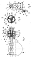
- the intermediate lever 3 carries also a further roller 60, which rests on the adjusting shaft 1.
- Fig. 3 can also be seen the camshaft 61, the cam 62 rests on a roller 63 of the intermediate lever 3.
- the intermediate lever 3 is known Swung back and forth, with the arm 6 of the roller lever 7 pivoted and thereby a valve stem 10 against the force at least one compression spring 11 is moved.
- the lower one (not shown) end of the valve stem 10 carries the valve with which the inlet opening in the combustion chamber of the engine cylinder closed becomes.
- the valve stem 10 is against the by the roller lever 7 Force shifted by at least one compression spring 11 when the valve should be opened.
- the compression spring 11 ensures that the valve with the corresponding position of the roller lever 7 in its closed position is pushed back. With the valve control it is possible to Vary the stroke of the valve stem 10. Since the intermediate lever 3 with the roller 4 abuts the cam 2 of the adjusting shaft 1, can be turned the adjusting shaft 1 about its axis the intermediate lever 3 more or swiveled less.
- the adjusting shaft 1 counterclockwise rotated, then is due to the abutment of the roller 4 on the cam 2 the intermediate lever 3 is also pivoted counterclockwise.
- the other arm 6 of the intermediate lever 3 the roller lever 7 adjusted accordingly, so that the valve stem 10 and thus the corresponding valve a larger stroke performs.
- the adjusting shaft 1 turns clockwise 3 rotated, then the intermediate lever pivots 3 clockwise due to its contact with cam 2. Accordingly the arm 6 of the roller lever 3 will also turn clockwise adjusted. This leads to the valve stem 10 correspondingly executes a smaller stroke.
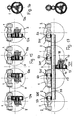
- the adjusting shaft 1 is coupled to a rotary drive 12 with which the adjusting shaft 11 can be rotated to a limited extent. It has a cylindrical one Stator 13 (FIG. 2), the two end faces of which are covered by cover disks 14, 15 are closed. Two rotors 16 and 17 are accommodated in the stator 13, of which the rotor 16 rotates with the adjusting shaft 1 connected is. The other rotor 17 sits on an axis 18 which is aligned with the adjusting shaft 1 and is mounted in the cylinder head 19.
- the Rotors 16, 17 have a cylindrical base body 21, 22, the Axis coincides with the axis of the stator 13 and of which Project wing 23 radially outward. These wings 23 also have an angular distance of 120 ° to each other.
- the rotors 16, 17 lie with the end faces of the wings 23 on the inner wall of the stator 13 on.
- the wings 20 of the stator 13 in turn lie on the outer wall of the cylindrical base body 21, 22.
- a wing 23 of the rotors 16, 17 lies between each two blades 20 of the stator 13.
- the blades 23 of the rotors 16, 17 are acted upon in a known manner with hydraulic medium, that through (not shown) holes in the spaces 24 of the stator 13 arrives.
- the wings 23 of the rotors 16, 17 can be on both Sides are pressurized so that the rotors 16, 17 clockwise and counterclockwise with respect to the stator 13 can be rotated.
- the two rotors 16, 17 are arranged axially with one another, have no connection with each other.
- the stator 13 has for both rotors 16, 17 have the corresponding pressure spaces 24.
- FIG. 1 shows, is from the inner wall of the stator 13 in half a length Ring wall 25, which has a central through opening 26. In they project tapered sections of the base body from both sides 21, 22 of the rotors 16, 17.
- the ring wall 25 lies with the edge of the Through opening 26 sealing at the tapered end portions the base body 21, 22 of the rotors 16, 17.
- the rotor 16 is in one piece formed with the adjusting shaft 1. But it can also be used as a separate Component to be connected to the adjusting shaft 1.
- the Adjustment shaft 1 projects through the cover disk 14 in a sealed manner.
- the rotor 17 projects with a tapered end section 27 through the cover plate 15 and lies on the end face of a wall of the cylinder head 19 on.
- the rotor 17 has a central through opening, in which the axis 18 is inserted.
- the two rotors 16, 17 are rotated independently of one another, since they with their wings 23 in the separate rooms 24 of the stator 13 are housed.
- the cover plates 14, 15 are with screws 28, 29 releasably attached to the ring wall 25.
- the rotors 16, 17 can be rotated about their axes as far as until their wings 23 come to rest on the wings 20 of the stator 13. As FIG. 2 shows by way of example, the maximum adjustment angle is 30 of the rotors 16, 17 90 °.
- the adjusting shaft 1 maximum can be rotated by 180 °.
- the pressure rooms 24 for the two Rotors 16, 17 are each acted upon by hydraulic medium.
- the shaft-side rotor 16 is in the starting position with its Wings 23 on the wings 20 of the stator 13.
- the wings 23 of the other rotors 17 are also on the stator blades 20. Both However, rotors 16, 17 are rotated against each other so that their wings rest on different stator blades 20, in the axial direction of the rotary drive 12 seen.
- the pressure spaces 24 for the stator 16 are first kept under pressure with the hydraulic medium, so that the rotor blades 23 on the stator blades 20 under the pressure of Apply hydraulic medium.
- the hydraulic medium is introduced under pressure so that the stator 12 is rotated relative to the rotor 17.
- the other rotor 16 lies with its wings 23 on the stator blades 20 that the Stator 12 takes this rotor 16 with it during the relative rotation. Thereby the adjusting shaft 1 is rotated about its axis.
- the wings 23 of the rotor 17 on one side with the hydraulic medium pressure acted upon from the other side the rotor blade 23 delimits part of the respective pressure chamber 24 is relieved of pressure.
- the hydraulic medium is kept under pressure so that this stop position is maintained.
- the hydraulic control for the rotor 16 is switched so that the rotor 16 can now rotate relative to the stator 12.
- the rotor blades 23 on one side with the under pressure standing hydraulic medium loaded while by the other Side of the rotor blades 23 limited part of the pressure chambers 24 relieved of pressure becomes.
- the adjusting shaft 1 is rotated twice by 90 °, that is, in total rotated by 180 ° at maximum around its axis.
- the roller lever 7 is pivoted back so far that the valve stem 10 is not operated.
- the intermediate lever 3 is turned counterclockwise Fig. 3 pivoted.
- the roller lever 7 is also pivoted counterclockwise. Because the arm 9 of the roller lever 7 acts on the valve stem 10, depending on the angle of rotation Adjustment shaft 1 of valve stem 10 more or less far down moved and thus the stroke of the valve according to the Power requirement set.
- the inlet valves Since the rotary drive 12 is actuated hydraulically, the inlet valves, when the motor vehicle engine is switched off, in its starting position to be led back. The inlet valves go here back to a position where they expose the smallest inlet opening.
- the fully variable valve control described is inexpensive and also easy to set up.
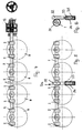
- Fig. 4 shows that with the adjusting shaft 1 and the rotary drive 12th several inlet valves can be operated simultaneously. On the Adjustment shaft 1 each sit at a distance several cams 2, each 3 to the corresponding drive Valve stems work. With the single rotary drive 12 can Embodiment eight cams 2 are operated on the corresponding Act valve stems and depending on the rotational position of the adjusting shaft 1 control the stroke of the valve.
- the adjusting shaft 1, eight according to the previous embodiment Cam 2 is sitting, no longer from one end, but in half Length rotatably driven.
- the adjusting shaft 1 has in the embodiment Half-round external teeth 31 into which a rack 32 of the rotary drive 12a engages.
- the Rack 32 sits on a piston rod 33, which consists of a cylinder 34 protrudes.
- the piston rod 33 carries within the cylinder 34 a piston 35 which seals in the cylinder 34 by means of hydraulic medium is movable.
- This embodiment is characterized by its constructive simplicity out.
- the rack and pinion drive ensures an exact stepless Rotation of the adjusting shaft 1 so that the stroke of the intake valves can be continuously adjusted accordingly.
- Z is one for each engine cylinder separate rotary drive 12a is provided, which according to the embodiment 5 and 6 is formed. Accordingly this fully variable valve control has four adjustment shafts 1 two cams each 2. This allows the intake valves to be independent can be variably adjusted from each other by the respective adjusting shaft 1 with the rotary drive 12a to their desired extent Axis is rotated.
- the rotary drives 12a are independent of one another supplied with hydraulic medium, so that a problem-free and reliable setting of the respective inlet valves guaranteed is.
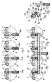
- the drive 12b a coarse adjustment device 36 and fine adjustment devices 37.
- the coarse adjustment device 36 With the coarse adjustment device 36, the fine adjustment devices 37, for each intake valve according to the embodiment 7 are individually provided, operated together. With the Fine adjustment 37 can then the individual adjustment shafts 1 fine-tuned to the extent necessary to be customized adjust the stroke of the intake valves.
- the coarse adjustment device 36 has a drive 38 with which one Intermediate shaft 39 can be rotatably driven. It is parallel to the mutually aligned adjusting shafts 1 and points in Area of a rack 40 on an external toothing 41, in which the rack 40 engages. She sits on top of a cylinder 42 protruding end of a piston rod 43, one at the other end Piston 44 carries, which is sealed in the cylinder 42. By Actuation of the piston 44 with a hydraulic medium can Piston rod 43 are extended and retracted so that the intermediate shaft 39 on the rack 40 in the desired direction can be rotated.
- the intermediate shaft 39 carrier 45 With the intermediate shaft 39 carrier 45 can be moved, the are designed in the form of a rack and with a corresponding External teeth 46 of the intermediate shaft 39 are engaged.
- the brackets 45 associated with the intake valves are the same formed and have a pressure chamber 47 in which a piston 48 is displaceable. It sits on the free end of a piston rod 49, which protrudes from the carrier 45 and carries a rack 50. she is engages with the external toothing 31 of the associated adjusting shaft 1.
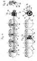
- the embodiment according to FIGS. 11 and 12 is essentially designed the same as the embodiment of FIGS. 8 to 10. Only the drive 12c has a different training than that of previous embodiment.
- This drive 12c has the same design like the drive 12 according to FIGS. 1 to 3.
- the rotor 16 is on provided one end of the intermediate shaft 39, advantageously in one piece trained with her.
- the drive 12c is otherwise the same like the rotary drive 12 according to FIGS. 1 to 3.
- the intermediate shaft 39 With the two rotors 16, 17 in the stator 13, the intermediate shaft 39 can be at most 180 ° to be rotated around its axis. This rotation of the intermediate shaft 39 is transferred to the carrier 45, which corresponds to the previous Embodiment shifted perpendicular to the axis of the adjusting shafts 1 become.
- the adjusting shafts are on the racks 50 1 rotated about their axes to the appropriate extent.
- the fine adjustment 37 a fine adjustment of the stroke each intake valve of the engine cylinder Z possible.
- the pistons 48 of the fine adjustment devices 37 by appropriate pressurization in their currently set position. Only when the rough setting is finished the fine adjustment devices are operated, if necessary, by acting on the pistons 48 with hydraulic medium be moved in the desired direction.
- FIGS. 13 and 14 is for the intake valves the engine cylinder Z the common adjusting shaft 1 is provided. Therefore, the valve stems 10 (Fig. 3) of the intake valves only be moved together.
- the drive 12d To drive the adjusting shaft 1 is the drive 12d provided. It has the cylindrical stator 13, in which a rotor 17 is rotatably mounted. He sits on axis 18, the is mounted in the cylinder head 19 (Fig. 13). In the pressure rooms 24 des The hydraulic medium is introduced into the stator 13. This will make the Stator 13 rotated relative to the rotor 17 in the manner described.
- the stator 13 has teeth on its outer jacket 51, which engages with an external toothing 52 of the adjusting shaft 1 is.
- the adjusting shaft 1 is rotated to the required extent.
- the angle of rotation of the stator 13 is only 90 °. This is why the gear ratio between the teeth 51 of the stator 13 and the external toothing 52 of the adjusting shaft 1 selected so that the adjusting shaft at a rotation angle of 90 ° of the stator 13 Rotates 180 °.
- the transmission of the rotation of the adjusting shaft 1 on the Valve stems 10 takes place via the intermediate drive, as it is based on Fig. 3 has been described.
- an adjusting shaft 1 is provided. This makes every adjustment shaft 1 assigned a rotary drive 12e. He is trained the same way the rotary drive 12d according to FIGS. 13 and 14. By means of the rotary drives 12e, the adjusting shafts 1 can be adjusted independently of one another required dimensions are rotatably driven. The valve stems the intake valves of the engine cylinder Z can therefore be independent of each other can be optimally moved.
- the 17 to 19 shows a rotary drive 12f, which is similar to that Embodiment according to FIGS. 8 to 10 a rough adjustment device 36f and fine adjustment devices 37f for the individual adjusting shafts 1 has.
- the coarse adjustment device 36f has the stator 13 in which the rotor 17 is housed, which sits on the axis 18. It is in Cylinder head 19 mounted.
- the stator 13 As with the embodiments according to the 13 to 16 is the stator 13 on the end face through the cover disks 14, 15 closed.
- the stator 13 has the external teeth 51.
- the hydraulic medium is introduced so that the stator 13 is rotated relative to the rotor 17.
- the maximum angle of rotation of the stator 13 is in the embodiment 90 °.
- Each swivel motor 53 has an outer ring 54 (FIG. 19) which is provided with an external toothing 55 with which the outer ring 54 engages in the external toothing 52 of the intermediate shaft 39.
- Wing 56 Stand radially inward from the inner wall of the outer ring 54 Wing 56, with its end faces on a cylindrical base body 57 of a rotor 58. It has directed radially outwards Wing 59, with its end faces on the inner wall of the outer ring 54 concerns.
- the rotor 58 can be rotated by a small angle be rotated within the outer ring 54 until its wings 59 on the side surfaces of one of the adjacent wings 56 of the Outer ring 54 come to rest.
- the rotor 58 is non-rotatable with the respective adjusting shaft 1 connected. Between wings 56, 59 the outer ring 54 and the rotor 58 is hydraulic medium under Pressure introduced so that the relative rotation of the rotor 58 opposite the outer ring 54 can be performed.
- Adjustment shafts 1 are provided, on which according to the embodiments 7 and 11 to 16 two each with axial Distance from each other cams are provided. With you the stems 10 (Fig. 3) of the intake valves are actuated as by reference 3 has been explained in detail.
- each cylinder there are for each cylinder the engine provided two intake valves. Depending on the type of engine additional intake valves per cylinder can be provided. In the simplest In this case, each cylinder has only one intake valve.
- valve controls are based on the exemplary embodiments Control of the stroke of intake valves has been described.
- the Valve controls can of course also be used for exhaust valves be used in the same way to increase their stroke accordingly change.
- the adjusting shaft 1 is in each case provided with cam 2.
- the adjusting shaft 1 can, however, with all Embodiments, for example, an eccentric shaft be, which in this case has no cams.
- Essential for the adjustment shaft is that when it rotates a transverse or radial component is generated, which is used over the transmission chain to move the valve stem 10 to the desired extent.
- the Transmission chain does not have to, as is exemplified in Fig. 3, be formed by mechanical components, but can for example also be a hydraulic transmission chain. It must just be sure that the engine's camshaft generated normal stroke of the valve stem 10 by the adjusting shaft 1 can be varied.
Priority Applications (1)
| Application Number | Priority Date | Filing Date | Title |
|---|---|---|---|
| EP07107909A EP1832723B1 (fr) | 2002-03-20 | 2003-03-12 | Commande de soupape pour régler la levée des soupapes dans un moteur à combustion interne |
Applications Claiming Priority (2)
| Application Number | Priority Date | Filing Date | Title |
|---|---|---|---|
| DE10213081A DE10213081A1 (de) | 2002-03-20 | 2002-03-20 | Ventilsteuerung zur Einstellung des Hubes von Ventilen in Kraftfahrzeugen |
| DE10213081 | 2002-03-20 |
Related Child Applications (1)
| Application Number | Title | Priority Date | Filing Date |
|---|---|---|---|
| EP07107909A Division EP1832723B1 (fr) | 2002-03-20 | 2003-03-12 | Commande de soupape pour régler la levée des soupapes dans un moteur à combustion interne |
Publications (3)
| Publication Number | Publication Date |
|---|---|
| EP1347154A2 true EP1347154A2 (fr) | 2003-09-24 |
| EP1347154A3 EP1347154A3 (fr) | 2003-12-17 |
| EP1347154B1 EP1347154B1 (fr) | 2008-08-27 |
Family
ID=27771515
Family Applications (2)
| Application Number | Title | Priority Date | Filing Date |
|---|---|---|---|
| EP03005576A Expired - Lifetime EP1347154B1 (fr) | 2002-03-20 | 2003-03-12 | Contrôleur de levée de soupapes d'un moteur à combustion interne |
| EP07107909A Expired - Lifetime EP1832723B1 (fr) | 2002-03-20 | 2003-03-12 | Commande de soupape pour régler la levée des soupapes dans un moteur à combustion interne |
Family Applications After (1)
| Application Number | Title | Priority Date | Filing Date |
|---|---|---|---|
| EP07107909A Expired - Lifetime EP1832723B1 (fr) | 2002-03-20 | 2003-03-12 | Commande de soupape pour régler la levée des soupapes dans un moteur à combustion interne |
Country Status (5)
| Country | Link |
|---|---|
| US (1) | US6814036B2 (fr) |
| EP (2) | EP1347154B1 (fr) |
| AT (2) | ATE459789T1 (fr) |
| DE (3) | DE10213081A1 (fr) |
| ES (1) | ES2312676T3 (fr) |
Cited By (12)
| Publication number | Priority date | Publication date | Assignee | Title |
|---|---|---|---|---|
| WO2007107428A2 (fr) | 2006-03-17 | 2007-09-27 | Hydraulik-Ring Gmbh | Circuit hydraulique, destiné en particulier à des dispositifs de réglage d'arbre à cames, et élément de commande correspondant |
| DE102006012775B4 (de) * | 2006-03-17 | 2008-01-31 | Hydraulik-Ring Gmbh | Fast cam phaser-Hydraulikkreis, insbesondere für Nockenwellenversteller, und entsprechendes Steuerelement |
| DE102006012733B4 (de) * | 2006-03-17 | 2008-03-27 | Hydraulik-Ring Gmbh | Fast cam phaser-Hydraulikkreis, insbesondere für Nockenwellenversteller, und entsprechendes Steuerelement |
| DE102008033230A1 (de) | 2008-01-04 | 2009-07-09 | Hydraulik-Ring Gmbh | Doppelter Nockenwellenversteller in Schichtaufbau |
| US7581527B2 (en) | 2006-11-28 | 2009-09-01 | Iveco S.P.A. | Internal combustion engine provided with a valve opening variation system and vehicle equipped with such engine |
| DE102008023098A1 (de) | 2008-05-09 | 2009-12-17 | Hydraulik-Ring Gmbh | Doppelter Nockenwellenversteller in Schichtaufbau |
| US7836857B2 (en) | 2006-03-17 | 2010-11-23 | Hydraulik-Ring Gmbh | Hydraulic circuit, particularly for camshaft adjusters, and corresponding control element |
| US7841311B2 (en) | 2008-01-04 | 2010-11-30 | Hilite International Inc. | Variable valve timing device |
| EP2386729A1 (fr) * | 2010-05-10 | 2011-11-16 | Fiat Powertrain Technologies S.p.A. | Moteur à combustion interne multicylindres ayant un actionnement variable des soupapes du moteur |
| EP2415979A1 (fr) | 2010-08-04 | 2012-02-08 | Hydraulik-Ring GmbH | Déphaseur d'arbre à cames |
| WO2012136409A1 (fr) * | 2011-04-04 | 2012-10-11 | Schaeffler Technologies AG & Co. KG | Déphaseur d'arbre à cames |
| DE102020113219A1 (de) | 2020-05-15 | 2021-11-18 | Schaeffler Technologies AG & Co. KG | Kipphebelanordnung für einen Ventiltrieb einer Brennkraftmaschine |
Families Citing this family (10)
| Publication number | Priority date | Publication date | Assignee | Title |
|---|---|---|---|---|
| DE102004020623A1 (de) * | 2004-04-27 | 2005-12-01 | Ina-Schaeffler Kg | Variable mechanische Ventiltriebsteuerung mit Verstelleinrichtung |
| DE102004058997A1 (de) * | 2004-12-08 | 2006-07-27 | Daimlerchrysler Ag | Brennkraftmaschine |
| DE102009022869A1 (de) * | 2009-05-27 | 2010-12-09 | Hydraulik-Ring Gmbh | Flügelzellennockenwellenverstellersystem |
| DE102009050779B4 (de) | 2009-10-27 | 2016-05-04 | Hilite Germany Gmbh | Schwenkmotornockenwellenversteller mit einer Reibscheibe und Montageverfahren |
| DE102009052841A1 (de) * | 2009-11-13 | 2011-05-19 | Hydraulik-Ring Gmbh | Nockenwelleneinsatz |
| DE102010045358A1 (de) | 2010-04-10 | 2011-10-13 | Hydraulik-Ring Gmbh | Schwenkmotornockenwellenversteller mit einem Hydraulikventil |
| DE102010019005B4 (de) | 2010-05-03 | 2017-03-23 | Hilite Germany Gmbh | Schwenkmotorversteller |
| DE102010061337B4 (de) | 2010-12-20 | 2015-07-09 | Hilite Germany Gmbh | Hydraulikventil für einen Schwenkmotorversteller |
| DE102011009416B4 (de) * | 2011-01-25 | 2016-11-03 | Kolbenschmidt Pierburg Innovations Gmbh | Mechanisch steuerbare Ventiltriebanordnung |
| DE102014114396A1 (de) * | 2014-10-02 | 2016-04-07 | Pierburg Gmbh | Mechanisch steuerbarer Ventiltrieb sowie mechanisch steuerbare Ventiltriebanordnung |
Citations (14)
| Publication number | Priority date | Publication date | Assignee | Title |
|---|---|---|---|---|
| US4858572A (en) * | 1987-09-30 | 1989-08-22 | Aisin Seiki Kabushiki Kaisha | Device for adjusting an angular phase difference between two elements |
| EP0405927A1 (fr) * | 1989-06-30 | 1991-01-02 | Suzuki Kabushiki Kaisha | Mécanisme d'entraînement de soupapes pour moteur à quatre temps |
| US5025761A (en) * | 1990-06-13 | 1991-06-25 | Chen Kuang Tong | Variable valve-timing device |
| EP0452671A2 (fr) * | 1990-03-14 | 1991-10-23 | Suzuki Kabushiki Kaisha | Dispositif de commande de soupape pour moteur à quatre temps |
| DE4116196A1 (de) * | 1991-05-17 | 1992-11-19 | Bosch Gmbh Robert | Nockenwelle-verstellvorrichtung fuer verbrennungsmotoren |
| US5189998A (en) * | 1991-07-23 | 1993-03-02 | Atsugi Unisia Corporation | Valve mechanism of internal combustion engine |
| EP0780547A1 (fr) * | 1995-12-22 | 1997-06-25 | Siemens Aktiengesellschaft | Dispositif permettant de varier la loi de leveé d'une soupape de moteur à combustion interne |
| DE19614558A1 (de) * | 1996-04-12 | 1997-10-16 | Schaeffler Waelzlager Kg | Vorrichtung zum Verändern der Öffnungs- und Schließzeiten von Gaswechselventilen einer Brennkraftmaschine |
| US5941203A (en) * | 1997-06-24 | 1999-08-24 | Aisin Seiki Kabushiki Kaisha | Valve timing control device |
| US6024061A (en) * | 1997-01-31 | 2000-02-15 | Denso Corporation | Valve timing adjusting apparatus for internal combustion engines |
| US6039015A (en) * | 1997-09-29 | 2000-03-21 | Aisin Seiki Kabushiki Kaisha | Valve timing control device |
| US6311656B1 (en) * | 1999-08-17 | 2001-11-06 | Unisia Jecs Corporation | Valve timing control apparatus for internal combustion engine |
| EP1234967A2 (fr) * | 2001-02-27 | 2002-08-28 | Nissan Motor Company, Limited | Méthode et dispositif pour mesurer la quantité d'air aspirée par un moteur à combustion interne |
| WO2002097244A1 (fr) * | 2001-05-30 | 2002-12-05 | Bishop Innovation Limited | Mecanisme de calage de distribution pour moteur a combustion interne a soupape rotative |
Family Cites Families (3)
| Publication number | Priority date | Publication date | Assignee | Title |
|---|---|---|---|---|
| US2911956A (en) * | 1959-01-07 | 1959-11-10 | Bryant Grinder Corp | Shaft positioner |
| JP3077621B2 (ja) * | 1996-04-09 | 2000-08-14 | トヨタ自動車株式会社 | 内燃機関の可変バルブタイミング機構 |
| FI108076B (fi) * | 1999-08-17 | 2001-11-15 | Esko Raikamo | Voimaelin venttiilien tms. asettamiseksi haluttuun asentoon |
-
2002
- 2002-03-20 DE DE10213081A patent/DE10213081A1/de not_active Withdrawn
-
2003
- 2003-03-12 AT AT07107909T patent/ATE459789T1/de not_active IP Right Cessation
- 2003-03-12 EP EP03005576A patent/EP1347154B1/fr not_active Expired - Lifetime
- 2003-03-12 AT AT03005576T patent/ATE406504T1/de not_active IP Right Cessation
- 2003-03-12 DE DE50312490T patent/DE50312490D1/de not_active Expired - Lifetime
- 2003-03-12 ES ES03005576T patent/ES2312676T3/es not_active Expired - Lifetime
- 2003-03-12 EP EP07107909A patent/EP1832723B1/fr not_active Expired - Lifetime
- 2003-03-12 DE DE50310394T patent/DE50310394D1/de not_active Expired - Lifetime
- 2003-03-20 US US10/249,173 patent/US6814036B2/en not_active Expired - Fee Related
Patent Citations (14)
| Publication number | Priority date | Publication date | Assignee | Title |
|---|---|---|---|---|
| US4858572A (en) * | 1987-09-30 | 1989-08-22 | Aisin Seiki Kabushiki Kaisha | Device for adjusting an angular phase difference between two elements |
| EP0405927A1 (fr) * | 1989-06-30 | 1991-01-02 | Suzuki Kabushiki Kaisha | Mécanisme d'entraînement de soupapes pour moteur à quatre temps |
| EP0452671A2 (fr) * | 1990-03-14 | 1991-10-23 | Suzuki Kabushiki Kaisha | Dispositif de commande de soupape pour moteur à quatre temps |
| US5025761A (en) * | 1990-06-13 | 1991-06-25 | Chen Kuang Tong | Variable valve-timing device |
| DE4116196A1 (de) * | 1991-05-17 | 1992-11-19 | Bosch Gmbh Robert | Nockenwelle-verstellvorrichtung fuer verbrennungsmotoren |
| US5189998A (en) * | 1991-07-23 | 1993-03-02 | Atsugi Unisia Corporation | Valve mechanism of internal combustion engine |
| EP0780547A1 (fr) * | 1995-12-22 | 1997-06-25 | Siemens Aktiengesellschaft | Dispositif permettant de varier la loi de leveé d'une soupape de moteur à combustion interne |
| DE19614558A1 (de) * | 1996-04-12 | 1997-10-16 | Schaeffler Waelzlager Kg | Vorrichtung zum Verändern der Öffnungs- und Schließzeiten von Gaswechselventilen einer Brennkraftmaschine |
| US6024061A (en) * | 1997-01-31 | 2000-02-15 | Denso Corporation | Valve timing adjusting apparatus for internal combustion engines |
| US5941203A (en) * | 1997-06-24 | 1999-08-24 | Aisin Seiki Kabushiki Kaisha | Valve timing control device |
| US6039015A (en) * | 1997-09-29 | 2000-03-21 | Aisin Seiki Kabushiki Kaisha | Valve timing control device |
| US6311656B1 (en) * | 1999-08-17 | 2001-11-06 | Unisia Jecs Corporation | Valve timing control apparatus for internal combustion engine |
| EP1234967A2 (fr) * | 2001-02-27 | 2002-08-28 | Nissan Motor Company, Limited | Méthode et dispositif pour mesurer la quantité d'air aspirée par un moteur à combustion interne |
| WO2002097244A1 (fr) * | 2001-05-30 | 2002-12-05 | Bishop Innovation Limited | Mecanisme de calage de distribution pour moteur a combustion interne a soupape rotative |
Cited By (20)
| Publication number | Priority date | Publication date | Assignee | Title |
|---|---|---|---|---|
| US7836857B2 (en) | 2006-03-17 | 2010-11-23 | Hydraulik-Ring Gmbh | Hydraulic circuit, particularly for camshaft adjusters, and corresponding control element |
| WO2007107428A3 (fr) * | 2006-03-17 | 2007-11-08 | Hydraulik Ring Gmbh | Circuit hydraulique, destiné en particulier à des dispositifs de réglage d'arbre à cames, et élément de commande correspondant |
| DE102006012775B4 (de) * | 2006-03-17 | 2008-01-31 | Hydraulik-Ring Gmbh | Fast cam phaser-Hydraulikkreis, insbesondere für Nockenwellenversteller, und entsprechendes Steuerelement |
| DE102006012733B4 (de) * | 2006-03-17 | 2008-03-27 | Hydraulik-Ring Gmbh | Fast cam phaser-Hydraulikkreis, insbesondere für Nockenwellenversteller, und entsprechendes Steuerelement |
| US7946266B2 (en) | 2006-03-17 | 2011-05-24 | Hydraulik-Ring Gmbh | Hydraulic circuit, particularly for camshaft adjusters, and corresponding control element |
| WO2007107428A2 (fr) | 2006-03-17 | 2007-09-27 | Hydraulik-Ring Gmbh | Circuit hydraulique, destiné en particulier à des dispositifs de réglage d'arbre à cames, et élément de commande correspondant |
| US7581527B2 (en) | 2006-11-28 | 2009-09-01 | Iveco S.P.A. | Internal combustion engine provided with a valve opening variation system and vehicle equipped with such engine |
| US8201528B2 (en) | 2008-01-04 | 2012-06-19 | Hilite Germany Gmbh | Doubled cam shaft adjuster in layered construction |
| US7841311B2 (en) | 2008-01-04 | 2010-11-30 | Hilite International Inc. | Variable valve timing device |
| DE102008033230A1 (de) | 2008-01-04 | 2009-07-09 | Hydraulik-Ring Gmbh | Doppelter Nockenwellenversteller in Schichtaufbau |
| DE102008033230B4 (de) * | 2008-01-04 | 2010-05-27 | Hydraulik-Ring Gmbh | Doppelter Nockenwellenversteller in Schichtaufbau |
| DE102008023098A1 (de) | 2008-05-09 | 2009-12-17 | Hydraulik-Ring Gmbh | Doppelter Nockenwellenversteller in Schichtaufbau |
| EP2386729A1 (fr) * | 2010-05-10 | 2011-11-16 | Fiat Powertrain Technologies S.p.A. | Moteur à combustion interne multicylindres ayant un actionnement variable des soupapes du moteur |
| WO2011141833A3 (fr) * | 2010-05-10 | 2012-01-05 | Fiat Powertrain Technologies S.P.A. | Moteur à combustion interne multicylindre doté de soupapes à actionnement variable |
| EP2415979A1 (fr) | 2010-08-04 | 2012-02-08 | Hydraulik-Ring GmbH | Déphaseur d'arbre à cames |
| DE102010033296A1 (de) | 2010-08-04 | 2012-02-09 | Hydraulik-Ring Gmbh | Nockenwellenversteller, insbesondere mit Nockenwelle |
| US8677960B2 (en) | 2010-08-04 | 2014-03-25 | Hilite Germany Gmbh | Camshaft adjuster, in particular with camshaft |
| WO2012136409A1 (fr) * | 2011-04-04 | 2012-10-11 | Schaeffler Technologies AG & Co. KG | Déphaseur d'arbre à cames |
| US9074498B2 (en) | 2011-04-04 | 2015-07-07 | Schaeffler Technologies AG & Co. KG | Camshaft phaser |
| DE102020113219A1 (de) | 2020-05-15 | 2021-11-18 | Schaeffler Technologies AG & Co. KG | Kipphebelanordnung für einen Ventiltrieb einer Brennkraftmaschine |
Also Published As
| Publication number | Publication date |
|---|---|
| ES2312676T3 (es) | 2009-03-01 |
| EP1347154B1 (fr) | 2008-08-27 |
| EP1832723A2 (fr) | 2007-09-12 |
| US6814036B2 (en) | 2004-11-09 |
| ATE406504T1 (de) | 2008-09-15 |
| DE50312490D1 (de) | 2010-04-15 |
| US20030177991A1 (en) | 2003-09-25 |
| EP1832723B1 (fr) | 2010-03-03 |
| ATE459789T1 (de) | 2010-03-15 |
| EP1347154A3 (fr) | 2003-12-17 |
| EP1832723A3 (fr) | 2007-09-26 |
| DE50310394D1 (de) | 2008-10-09 |
| DE10213081A1 (de) | 2003-10-02 |
Similar Documents
| Publication | Publication Date | Title |
|---|---|---|
| EP1347154B1 (fr) | Contrôleur de levée de soupapes d'un moteur à combustion interne | |
| DE10230108B4 (de) | Vorrichtung zum Verstellen des Hubs eines von einer Nockenwelle betätigten Ventils | |
| EP2415979B1 (fr) | Déphaseur d'arbre à cames | |
| DE3690061C2 (de) | Rotationskolbenmaschine | |
| DE102015200139B4 (de) | Nockenwellenverstelleranbindung an eine Doppelnockenwelle | |
| WO2001061154A1 (fr) | Dispositif servant a modifier les temps de commande de soupapes d'echanges gazeux d'un moteur thermique | |
| DE3810804A1 (de) | Vorrichtung zur relativen winkelverstellung zwischen zwei in antriebsverbindung stehenden wellen | |
| EP2486248B1 (fr) | Agencement d'arbre à cames | |
| DE112015002518B4 (de) | Nockenwellenverstellersysteme und zugehörige Versteller mit Verriegelung | |
| DE102011116130A1 (de) | Ventiltrieb für eine Brennkraftmaschine | |
| DE102011079183A1 (de) | Nockenwellenversteller | |
| WO2008135420A1 (fr) | Déphaseur d'arbre à cames pour un moteur à combustion interne comprenant une mise en œuvre améliorée des chambres de pression | |
| DE19755495A1 (de) | Verriegelungseinrichtung für eine Vorrichtung zum Verändern der Steuerzeiten von Gaswechselventilen einer Brennkraftmaschine | |
| DE10351223A1 (de) | Nockenwellenverstelleinrichtung für Fahrzeuge, vorzugsweise für Kraftfahrzeuge | |
| DE60300177T2 (de) | Variabler Nockenversteller mit Schneckengetriebe | |
| EP1803904A2 (fr) | Arbre à cames | |
| EP1593880B1 (fr) | Arbre de commande pour une commande de soupapes à levée variable | |
| WO2002042613A1 (fr) | Dispositif de reglage de l"angle de rotation de l"arbre a cames d"un moteur a combustion interne par rapport a une roue d"entrainement | |
| DE102016113646A1 (de) | Exzenter-Verstelleinrichtung zur Verstellung einer effektiven Pleuellänge eines Pleuels einer Brennkraftmaschine | |
| EP1706604B1 (fr) | Dispositif pour modifier les temps de commande de soupapes d'echange gazeux d'un moteur a combustion interne, en particulier un dispositif d'ajustement de pistons de rotation permettant un ajustage de l'angle de rotation entre un arbre a cames et un vilebrequin | |
| DE10036546B4 (de) | Vorrichtung zum Verändern der Steuerzeiten von Gaswechselventilen einer Brennkraftmaschine, insbesondere hydraulische Nockenwellen-Verstelleinrichtungen in Rotationskolbenbauart | |
| DE4036010A1 (de) | Verstellbarer nockenwellenantrieb fuer eine brennkraftmaschine | |
| WO2000068547A1 (fr) | Dispositif de reglage de l'angle de rotation d'un arbre a cames par rapport au vilebrequin d'un moteur a combustion interne a piston | |
| EP2837779B1 (fr) | Commande de soupape pour une soupape d'échange de gaz d'un moteur à combustion interne | |
| DE102004001343A1 (de) | Variable Ventilsteuerungsvorrichtung mit Nockenwellenverstellung und Ventilhubkonturveränderung |
Legal Events
| Date | Code | Title | Description |
|---|---|---|---|
| PUAI | Public reference made under article 153(3) epc to a published international application that has entered the european phase |
Free format text: ORIGINAL CODE: 0009012 |
|
| AK | Designated contracting states |
Kind code of ref document: A2 Designated state(s): AT BE BG CH CY CZ DE DK EE ES FI FR GB GR HU IE IT LI LU MC NL PT SE SI SK TR |
|
| AX | Request for extension of the european patent |
Extension state: AL LT LV MK RO |
|
| PUAL | Search report despatched |
Free format text: ORIGINAL CODE: 0009013 |
|
| AK | Designated contracting states |
Kind code of ref document: A3 Designated state(s): AT BE BG CH CY CZ DE DK EE ES FI FR GB GR HU IE IT LI LU MC NL PT SE SI SK TR |
|
| AX | Request for extension of the european patent |
Extension state: AL LT LV MK RO |
|
| RIC1 | Information provided on ipc code assigned before grant |
Ipc: 7F 01L 1/344 B Ipc: 7F 02D 13/02 B Ipc: 7F 01L 25/02 B Ipc: 7F 01L 1/34 B Ipc: 7F 01L 13/00 A Ipc: 7F 02D 41/00 B |
|
| 17P | Request for examination filed |
Effective date: 20040521 |
|
| 17Q | First examination report despatched |
Effective date: 20040726 |
|
| AKX | Designation fees paid |
Designated state(s): AT BE BG CH CY CZ DE DK EE ES FI FR GB GR HU IE IT LI LU MC NL PT SE SI SK TR |
|
| RAP1 | Party data changed (applicant data changed or rights of an application transferred) |
Owner name: HYDRAULIK-RING GMBH |
|
| 17Q | First examination report despatched |
Effective date: 20040726 |
|
| GRAP | Despatch of communication of intention to grant a patent |
Free format text: ORIGINAL CODE: EPIDOSNIGR1 |
|
| GRAS | Grant fee paid |
Free format text: ORIGINAL CODE: EPIDOSNIGR3 |
|
| GRAA | (expected) grant |
Free format text: ORIGINAL CODE: 0009210 |
|
| AK | Designated contracting states |
Kind code of ref document: B1 Designated state(s): AT BE BG CH CY CZ DE DK EE ES FI FR GB GR HU IE IT LI LU MC NL PT SE SI SK TR |
|
| REG | Reference to a national code |
Ref country code: GB Ref legal event code: FG4D Free format text: NOT ENGLISH |
|
| REG | Reference to a national code |
Ref country code: CH Ref legal event code: EP |
|
| REG | Reference to a national code |
Ref country code: IE Ref legal event code: FG4D Free format text: LANGUAGE OF EP DOCUMENT: GERMAN |
|
| REF | Corresponds to: |
Ref document number: 50310394 Country of ref document: DE Date of ref document: 20081009 Kind code of ref document: P |
|
| REG | Reference to a national code |
Ref country code: SE Ref legal event code: TRGR |
|
| PG25 | Lapsed in a contracting state [announced via postgrant information from national office to epo] |
Ref country code: NL Free format text: LAPSE BECAUSE OF FAILURE TO SUBMIT A TRANSLATION OF THE DESCRIPTION OR TO PAY THE FEE WITHIN THE PRESCRIBED TIME-LIMIT Effective date: 20080827 |
|
| PG25 | Lapsed in a contracting state [announced via postgrant information from national office to epo] |
Ref country code: FI Free format text: LAPSE BECAUSE OF FAILURE TO SUBMIT A TRANSLATION OF THE DESCRIPTION OR TO PAY THE FEE WITHIN THE PRESCRIBED TIME-LIMIT Effective date: 20080827 Ref country code: SI Free format text: LAPSE BECAUSE OF FAILURE TO SUBMIT A TRANSLATION OF THE DESCRIPTION OR TO PAY THE FEE WITHIN THE PRESCRIBED TIME-LIMIT Effective date: 20080827 |
|
| REG | Reference to a national code |
Ref country code: ES Ref legal event code: FG2A Ref document number: 2312676 Country of ref document: ES Kind code of ref document: T3 |
|
| REG | Reference to a national code |
Ref country code: IE Ref legal event code: FD4D |
|
| PG25 | Lapsed in a contracting state [announced via postgrant information from national office to epo] |
Ref country code: DK Free format text: LAPSE BECAUSE OF FAILURE TO SUBMIT A TRANSLATION OF THE DESCRIPTION OR TO PAY THE FEE WITHIN THE PRESCRIBED TIME-LIMIT Effective date: 20080827 Ref country code: IE Free format text: LAPSE BECAUSE OF FAILURE TO SUBMIT A TRANSLATION OF THE DESCRIPTION OR TO PAY THE FEE WITHIN THE PRESCRIBED TIME-LIMIT Effective date: 20080827 Ref country code: BG Free format text: LAPSE BECAUSE OF FAILURE TO SUBMIT A TRANSLATION OF THE DESCRIPTION OR TO PAY THE FEE WITHIN THE PRESCRIBED TIME-LIMIT Effective date: 20081127 |
|
| PG25 | Lapsed in a contracting state [announced via postgrant information from national office to epo] |
Ref country code: SK Free format text: LAPSE BECAUSE OF FAILURE TO SUBMIT A TRANSLATION OF THE DESCRIPTION OR TO PAY THE FEE WITHIN THE PRESCRIBED TIME-LIMIT Effective date: 20080827 Ref country code: PT Free format text: LAPSE BECAUSE OF FAILURE TO SUBMIT A TRANSLATION OF THE DESCRIPTION OR TO PAY THE FEE WITHIN THE PRESCRIBED TIME-LIMIT Effective date: 20090127 Ref country code: CZ Free format text: LAPSE BECAUSE OF FAILURE TO SUBMIT A TRANSLATION OF THE DESCRIPTION OR TO PAY THE FEE WITHIN THE PRESCRIBED TIME-LIMIT Effective date: 20080827 |
|
| PLBE | No opposition filed within time limit |
Free format text: ORIGINAL CODE: 0009261 |
|
| STAA | Information on the status of an ep patent application or granted ep patent |
Free format text: STATUS: NO OPPOSITION FILED WITHIN TIME LIMIT |
|
| PG25 | Lapsed in a contracting state [announced via postgrant information from national office to epo] |
Ref country code: EE Free format text: LAPSE BECAUSE OF FAILURE TO SUBMIT A TRANSLATION OF THE DESCRIPTION OR TO PAY THE FEE WITHIN THE PRESCRIBED TIME-LIMIT Effective date: 20080827 |
|
| 26N | No opposition filed |
Effective date: 20090528 |
|
| PG25 | Lapsed in a contracting state [announced via postgrant information from national office to epo] |
Ref country code: IT Free format text: LAPSE BECAUSE OF FAILURE TO SUBMIT A TRANSLATION OF THE DESCRIPTION OR TO PAY THE FEE WITHIN THE PRESCRIBED TIME-LIMIT Effective date: 20080827 |
|
| BERE | Be: lapsed |
Owner name: HYDRAULIK-RING G.M.B.H. Effective date: 20090331 |
|
| PG25 | Lapsed in a contracting state [announced via postgrant information from national office to epo] |
Ref country code: MC Free format text: LAPSE BECAUSE OF NON-PAYMENT OF DUE FEES Effective date: 20090331 |
|
| REG | Reference to a national code |
Ref country code: CH Ref legal event code: PL |
|
| EUG | Se: european patent has lapsed | ||
| GBPC | Gb: european patent ceased through non-payment of renewal fee |
Effective date: 20090312 |
|
| PG25 | Lapsed in a contracting state [announced via postgrant information from national office to epo] |
Ref country code: LI Free format text: LAPSE BECAUSE OF NON-PAYMENT OF DUE FEES Effective date: 20090331 Ref country code: CH Free format text: LAPSE BECAUSE OF NON-PAYMENT OF DUE FEES Effective date: 20090331 |
|
| PG25 | Lapsed in a contracting state [announced via postgrant information from national office to epo] |
Ref country code: BE Free format text: LAPSE BECAUSE OF NON-PAYMENT OF DUE FEES Effective date: 20090331 |
|
| PG25 | Lapsed in a contracting state [announced via postgrant information from national office to epo] |
Ref country code: GB Free format text: LAPSE BECAUSE OF NON-PAYMENT OF DUE FEES Effective date: 20090312 |
|
| REG | Reference to a national code |
Ref country code: ES Ref legal event code: FD2A Effective date: 20090313 |
|
| PG25 | Lapsed in a contracting state [announced via postgrant information from national office to epo] |
Ref country code: AT Free format text: LAPSE BECAUSE OF NON-PAYMENT OF DUE FEES Effective date: 20090312 |
|
| PG25 | Lapsed in a contracting state [announced via postgrant information from national office to epo] |
Ref country code: ES Free format text: LAPSE BECAUSE OF NON-PAYMENT OF DUE FEES Effective date: 20090313 |
|
| PG25 | Lapsed in a contracting state [announced via postgrant information from national office to epo] |
Ref country code: GR Free format text: LAPSE BECAUSE OF FAILURE TO SUBMIT A TRANSLATION OF THE DESCRIPTION OR TO PAY THE FEE WITHIN THE PRESCRIBED TIME-LIMIT Effective date: 20081128 |
|
| PG25 | Lapsed in a contracting state [announced via postgrant information from national office to epo] |
Ref country code: LU Free format text: LAPSE BECAUSE OF NON-PAYMENT OF DUE FEES Effective date: 20090312 |
|
| PG25 | Lapsed in a contracting state [announced via postgrant information from national office to epo] |
Ref country code: SE Free format text: LAPSE BECAUSE OF NON-PAYMENT OF DUE FEES Effective date: 20090313 |
|
| PG25 | Lapsed in a contracting state [announced via postgrant information from national office to epo] |
Ref country code: HU Free format text: LAPSE BECAUSE OF FAILURE TO SUBMIT A TRANSLATION OF THE DESCRIPTION OR TO PAY THE FEE WITHIN THE PRESCRIBED TIME-LIMIT Effective date: 20090228 |
|
| PG25 | Lapsed in a contracting state [announced via postgrant information from national office to epo] |
Ref country code: TR Free format text: LAPSE BECAUSE OF FAILURE TO SUBMIT A TRANSLATION OF THE DESCRIPTION OR TO PAY THE FEE WITHIN THE PRESCRIBED TIME-LIMIT Effective date: 20080827 |
|
| PG25 | Lapsed in a contracting state [announced via postgrant information from national office to epo] |
Ref country code: CY Free format text: LAPSE BECAUSE OF FAILURE TO SUBMIT A TRANSLATION OF THE DESCRIPTION OR TO PAY THE FEE WITHIN THE PRESCRIBED TIME-LIMIT Effective date: 20080827 |
|
| REG | Reference to a national code |
Ref country code: DE Ref legal event code: R081 Ref document number: 50310394 Country of ref document: DE Owner name: HILITE GERMANY GMBH, DE Free format text: FORMER OWNER: HYDRAULIK-RING GMBH, 97828 MARKTHEIDENFELD, DE Effective date: 20130521 |
|
| PGFP | Annual fee paid to national office [announced via postgrant information from national office to epo] |
Ref country code: DE Payment date: 20140319 Year of fee payment: 12 |
|
| PGFP | Annual fee paid to national office [announced via postgrant information from national office to epo] |
Ref country code: FR Payment date: 20140319 Year of fee payment: 12 |
|
| REG | Reference to a national code |
Ref country code: DE Ref legal event code: R119 Ref document number: 50310394 Country of ref document: DE |
|
| REG | Reference to a national code |
Ref country code: FR Ref legal event code: ST Effective date: 20151130 |
|
| PG25 | Lapsed in a contracting state [announced via postgrant information from national office to epo] |
Ref country code: DE Free format text: LAPSE BECAUSE OF NON-PAYMENT OF DUE FEES Effective date: 20151001 |
|
| PG25 | Lapsed in a contracting state [announced via postgrant information from national office to epo] |
Ref country code: FR Free format text: LAPSE BECAUSE OF NON-PAYMENT OF DUE FEES Effective date: 20150331 |