EP1230698B1 - Cathode tubes - Google Patents
Cathode tubes Download PDFInfo
- Publication number
- EP1230698B1 EP1230698B1 EP00970812A EP00970812A EP1230698B1 EP 1230698 B1 EP1230698 B1 EP 1230698B1 EP 00970812 A EP00970812 A EP 00970812A EP 00970812 A EP00970812 A EP 00970812A EP 1230698 B1 EP1230698 B1 EP 1230698B1
- Authority
- EP
- European Patent Office
- Prior art keywords
- cathode
- tube
- coating mix
- binder
- zinc
- Prior art date
- Legal status (The legal status is an assumption and is not a legal conclusion. Google has not performed a legal analysis and makes no representation as to the accuracy of the status listed.)
- Expired - Lifetime
Links
Images

Classifications
-
- H—ELECTRICITY
- H01—ELECTRIC ELEMENTS
- H01M—PROCESSES OR MEANS, e.g. BATTERIES, FOR THE DIRECT CONVERSION OF CHEMICAL ENERGY INTO ELECTRICAL ENERGY
- H01M4/00—Electrodes
- H01M4/86—Inert electrodes with catalytic activity, e.g. for fuel cells
- H01M4/96—Carbon-based electrodes
-
- H—ELECTRICITY
- H01—ELECTRIC ELEMENTS
- H01M—PROCESSES OR MEANS, e.g. BATTERIES, FOR THE DIRECT CONVERSION OF CHEMICAL ENERGY INTO ELECTRICAL ENERGY
- H01M4/00—Electrodes
- H01M4/02—Electrodes composed of, or comprising, active material
- H01M4/06—Electrodes for primary cells
- H01M4/08—Processes of manufacture
-
- H—ELECTRICITY
- H01—ELECTRIC ELEMENTS
- H01M—PROCESSES OR MEANS, e.g. BATTERIES, FOR THE DIRECT CONVERSION OF CHEMICAL ENERGY INTO ELECTRICAL ENERGY
- H01M4/00—Electrodes
- H01M4/86—Inert electrodes with catalytic activity, e.g. for fuel cells
- H01M4/88—Processes of manufacture
- H01M4/8803—Supports for the deposition of the catalytic active composition
-
- H—ELECTRICITY
- H01—ELECTRIC ELEMENTS
- H01M—PROCESSES OR MEANS, e.g. BATTERIES, FOR THE DIRECT CONVERSION OF CHEMICAL ENERGY INTO ELECTRICAL ENERGY
- H01M4/00—Electrodes
- H01M4/86—Inert electrodes with catalytic activity, e.g. for fuel cells
- H01M4/88—Processes of manufacture
- H01M4/8825—Methods for deposition of the catalytic active composition
- H01M4/8864—Extrusion
-
- H—ELECTRICITY
- H01—ELECTRIC ELEMENTS
- H01M—PROCESSES OR MEANS, e.g. BATTERIES, FOR THE DIRECT CONVERSION OF CHEMICAL ENERGY INTO ELECTRICAL ENERGY
- H01M4/00—Electrodes
- H01M4/86—Inert electrodes with catalytic activity, e.g. for fuel cells
- H01M4/88—Processes of manufacture
- H01M4/8875—Methods for shaping the electrode into free-standing bodies, like sheets, films or grids, e.g. moulding, hot-pressing, casting without support, extrusion without support
-
- H—ELECTRICITY
- H01—ELECTRIC ELEMENTS
- H01M—PROCESSES OR MEANS, e.g. BATTERIES, FOR THE DIRECT CONVERSION OF CHEMICAL ENERGY INTO ELECTRICAL ENERGY
- H01M6/00—Primary cells; Manufacture thereof
- H01M6/04—Cells with aqueous electrolyte
- H01M6/06—Dry cells, i.e. cells wherein the electrolyte is rendered non-fluid
- H01M6/08—Dry cells, i.e. cells wherein the electrolyte is rendered non-fluid with cup-shaped electrodes
- H01M6/085—Dry cells, i.e. cells wherein the electrolyte is rendered non-fluid with cup-shaped electrodes of the reversed type, i.e. anode in the centre
-
- H—ELECTRICITY
- H01—ELECTRIC ELEMENTS
- H01M—PROCESSES OR MEANS, e.g. BATTERIES, FOR THE DIRECT CONVERSION OF CHEMICAL ENERGY INTO ELECTRICAL ENERGY
- H01M12/00—Hybrid cells; Manufacture thereof
- H01M12/04—Hybrid cells; Manufacture thereof composed of a half-cell of the fuel-cell type and of a half-cell of the primary-cell type
- H01M12/06—Hybrid cells; Manufacture thereof composed of a half-cell of the fuel-cell type and of a half-cell of the primary-cell type with one metallic and one gaseous electrode
-
- H—ELECTRICITY
- H01—ELECTRIC ELEMENTS
- H01M—PROCESSES OR MEANS, e.g. BATTERIES, FOR THE DIRECT CONVERSION OF CHEMICAL ENERGY INTO ELECTRICAL ENERGY
- H01M4/00—Electrodes
- H01M4/02—Electrodes composed of, or comprising, active material
- H01M2004/023—Gel electrode
-
- H—ELECTRICITY
- H01—ELECTRIC ELEMENTS
- H01M—PROCESSES OR MEANS, e.g. BATTERIES, FOR THE DIRECT CONVERSION OF CHEMICAL ENERGY INTO ELECTRICAL ENERGY
- H01M4/00—Electrodes
- H01M4/02—Electrodes composed of, or comprising, active material
- H01M2004/026—Electrodes composed of, or comprising, active material characterised by the polarity
- H01M2004/028—Positive electrodes
-
- H—ELECTRICITY
- H01—ELECTRIC ELEMENTS
- H01M—PROCESSES OR MEANS, e.g. BATTERIES, FOR THE DIRECT CONVERSION OF CHEMICAL ENERGY INTO ELECTRICAL ENERGY
- H01M4/00—Electrodes
- H01M4/02—Electrodes composed of, or comprising, active material
-
- H—ELECTRICITY
- H01—ELECTRIC ELEMENTS
- H01M—PROCESSES OR MEANS, e.g. BATTERIES, FOR THE DIRECT CONVERSION OF CHEMICAL ENERGY INTO ELECTRICAL ENERGY
- H01M4/00—Electrodes
- H01M4/02—Electrodes composed of, or comprising, active material
- H01M4/04—Processes of manufacture in general
- H01M4/0473—Filling tube-or pockets type electrodes; Applying active mass in cup-shaped terminals
-
- Y—GENERAL TAGGING OF NEW TECHNOLOGICAL DEVELOPMENTS; GENERAL TAGGING OF CROSS-SECTIONAL TECHNOLOGIES SPANNING OVER SEVERAL SECTIONS OF THE IPC; TECHNICAL SUBJECTS COVERED BY FORMER USPC CROSS-REFERENCE ART COLLECTIONS [XRACs] AND DIGESTS
- Y02—TECHNOLOGIES OR APPLICATIONS FOR MITIGATION OR ADAPTATION AGAINST CLIMATE CHANGE
- Y02E—REDUCTION OF GREENHOUSE GAS [GHG] EMISSIONS, RELATED TO ENERGY GENERATION, TRANSMISSION OR DISTRIBUTION
- Y02E60/00—Enabling technologies; Technologies with a potential or indirect contribution to GHG emissions mitigation
- Y02E60/10—Energy storage using batteries
Definitions
- the invention generally relates to electrochemical cells.
- a battery contains a negative electrode, typically called the anode, and a positive electrode, typically called the cathode.
- the anode contains an active material that can be oxidized; the cathode contains or consumes an active material that can be reduced.
- the anode active material is capable of reducing the cathode active material.
- the anode and the cathode are electrically isolated from each other by a sheet-like layer, typically called the separator.
- a battery When a battery is used as an electrical energy source in a device, such as a hearing aid or a cellular telephone, electrical contact is made to the anode and the cathode, allowing electrons to flow through the device and permitting the respective oxidation and reduction reactions to occur to provide electrical power.
- An electrolyte in contact with the anode and the cathode contains ions that flow through the separator between the electrodes to maintain charge balance throughout the battery during discharge.
- the cathode structure contains a material that can catalyze the reduction of oxygen which enters the cell as a component of atmospheric air passing through access ports in the container.
- Zinc oxide, or zincate is formed in the anode.
- the overall electrochemical reaction within the cell results in zinc metal being oxidized to zinc ions and oxygen from the air being reduced to hydroxyl ions. While these chemical reactions are taking place, electrons are transferred from the anode to the cathode, providing power to the device.
- Zinc cathode materials have traditionally been manufactured using flat processes such as dry coating and paste coating. For use in cylindrical zinc air batteries, the flat cathode sheets are welded together to create a cathode tube. Cathode tubes made by such processes typically have a seam were the edges of the sheet are welded together to form the cylindrical structure.
- GB 407 994 discloses a method of pasting a tubular electrode by placing a tubular conductor within a supporting mould and charging the tubular conductor with the pasting material and compressing the material outwardly into contact with the tubular conductor walls by means of a ram forced axially into the conductor.
- the inside of the casing is pasted with a layer of negative active material which is in the form of an uninterrupted tube.
- a battery in which the tubular electrode is used is disclosed.
- the invention relates to cathode tubes for metal air electrochemical cells and methods for making the cathode tubes.
- the cathode tubes are seamless. Unlike cathode tubes made by flat processed materials which have reduced ionic conversion at the seam, the seamless cathode tubes allow for the total surface of the tube to be utilized for conversion of hydroxyl ions.
- production of a seamless cathode tube eliminates the potential for leakage at the seam of the tube.
- electrochemical cells including these seamless cathode tubes can therefore be used to produce seamless cathode tubes for use in electrochemical cells which have good discharge characteristics and leakage resistance.
- the invention features a method of making a seamless cathode tube.
- the method includes applying a cathode coating mix to a current collector tube, the cathode coating mix stiffening to form a seamless cathode tube.
- the cathode tube is made by applying a coating mix which includes a binder, e.g., a polymer, which is hydrophobic and/or has a fibrous final state.
- binders include polytetrafluoroethylene (PTFE), PTFE copolymers, polyvinylidenefluoride (PVDF), hexofluoropvopalene (HFP)/ polyvinylidenefluoride (PVDF) copolymers, HFP/PVDF/PTFE tetrapolymers, polyethylene (PE) and ultrahydrated PE.
- the coating mix can be applied onto the current collector tube, e.g., a screen tube, such that a binder such as PTFE fibrillates and the cathode coating mix stiffens to form a seamless cathode tube.
- Methods of applying the coating mix such that the binder fibrillates include continuous extrusion, impact extrusion, compression molding, transfer molding and injection molding. These methods push binder particles past each other resulting in stretching and fiber formation, i.e., fibrillation. In addition, these methods induce fibrillation later in the processing stage, e.g., as the coating mix is being applied to the current collector, thereby avoiding overstretching of the binder fibers which can occur if fibrillation happens too early in the process.
- a method of making a seamless cathode tube characterized by applying a cathode coating mix comprising a binder to a current collector tube so as to induce fibrillation of the binder and effect stiffening of the cathode coating mix to form a seamless cathode tube.
- a binder such as PTFE.
- PTFE is hydrophobic and resists wetting, thereby creating pathways for oxygen to enter the cathode structure.
- PTFE due to its very high molecular weight, PTFE has inherent fibrillation properties. The particle to particle contact of fibrillation results in voids.
- a binder such as PTFE provides porosity to the finished cathode tube.
- PTFE also provides structural integrity and flexibility to the finished cathode tube.
- the cathode coating mix can also include a solvent.
- a solvent to the coating mix has several advantages.
- the addition of a solvent to the coating mix forms a flowable mixture that can be applied to the current collector tube using extrusion, e.g., continuous or impact extrusion, or molding, e.g., compression, transfer, or injection molding.
- the solvent can serve as a lubricant to control fibrillation of the binder, thereby decreasing the amount of fibrillation that occurs prior to application of the mix to the current collector tube.
- the solvent can later be removed from the cathode tube during a lubricant/solvent removal step.
- the invention features a method of making a seamless cathode tube by injection molding.
- the method can include placing a current collector tube into a molding cavity, and injecting a cathode coating mix.
- the cathode coating mix stiffens to form a seamless cathode tube.
- the method can also include injection molding the cathode mix into a tube.
- the production of seamless cathode tubes by injection molding results in a more efficient assembly process which can be used to produce discrete finished parts.
- the injection molding process as compared to converting flat sheet material, results in fewer process steps and components to complete the cathode sub assembly and subassembly of the electrochemical cell itself.
- the production of seamless cathode tubes by injection molding provides a more homogenous structure that flat sheets that are converted into tubes. The methods of making seamless cathode tubes using injection molding can therefore be used to make seamless cathode tubes having good performance characteristics made in a high rate assembly process.
- the methods can be used to make seamless cathode tubes for use in electrochemical cells such as zinc air cells.
- the cathode structure includes a current collector, such as a wire screen, upon which is deposited a cathode mixture.
- a current collector such as a wire screen
- the current collector tube refers to a tube which ultimately will function as a current collector.
- the wire mesh makes electrical contact with the cathode can.
- a cathode screen tube is formed, for example, by folding the edges of the mesh over each other, cold rolling, or fastening the edges together by stapling, welding or use of an adhesive.
- Methods of welding include ultrasonic welding, laser welding, resistance welding, pressure bonding and plasma welding.
- a seamless screen tube can be formed.
- Methods for forming a seamless screen tube include helical strip winding, wire braiding and the use of helical woven mesh.
- the outside of this tube faces the air access ports and can be covered by a microporous membrane, e.g., a polytetrafluoroethylene (PTFE) membrane, that can help prevent drying of the anode gel and leakage of electrolyte from the cell.
- the PTFE can in turn be covered by an air disperser, or blotter material.
- the air disperser is an porous or fibrous material that helps maintain an air diffusion space between the PTFE membrane and the cathode can.
- the cathode screen tube is then placed in an injection molding cavity.
- a microporous membrane e.g., a PTFE membrane, may be wrapped or heat-shrinked around the screen prior to being placed in the cavity.
- the active cathode coating mix is then injected into the injection cavity.
- the catalyst mixture is composed of a mixture of a binder, carbon particles, a solvent and a catalyst for reducing oxygen, such as a manganese compound.
- the binder is a polymer that has one or more of the following characteristics: 1) it is hydrophobic; and 2) it has a fibrous final state.
- a "fibrous final state” refers both to polymers which are fibrous prior to use in the methods of the invention and polymers which become fibrous by a processing step, e.g., extrusion or molding. Various extrusion and molding techniques are disclosed in The Plastics Engineering Handbook , pp. 204-240.
- binders include PTFE, PTFE copolymers, PVDF, HFP/PVDF copolymers, HFP/PVDF/PTFE tetrapolymers, polyethylene (PE) and ultrahydrated PE.
- Solvents which can be used in the coating mix include water, paraffin oils such as but not limited to isopar, e.g., isopar G or isopar M, isopropanol and diethyl glycol monobutyl ether.
- the paraffin oil has a distillation range of 160°C to 311°C (320°F to 592°F).
- the catalyst mixture can be prepared, for example, by heating manganese nitrate or by reducing potassium permanganate to produce manganese oxides, such as Mn 2 O 3 , Mn 3 O 4 , and MnO 2 .
- the coating mixture can include between about 3 and 75 percent, about 15 and 45 percent, about 20 and 40 percent, about 30 and 35 percent PTFE by weight. If the mixture contains PTFE, when the mix is forced into the cavity the PTFE fibrillates, or stretches, which in turn strengthens the structure. This allows the mix and screen to be strong enough to stand upright without additional support.
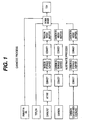
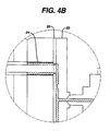
- Figures 4A and 4B set forth the basic elements of injection molding.
- the coating mix can be added into a hopper (10), which drops the coating mixture onto a barrel (12) and screw (14) device.
- a screw driver motor (16) connected to an injection cylinder (18) turns the screw (14) and moves the screw (14) up and down through the barrel.
- the coating mix is moved by the screw (14) into a runner system (22).
- the runner system (22) injects the coating mix into the molding cavity (24) through a ring gate system (26).
- the ring gate (26) can be slidable, thereby providing temporary separation between the runner system (22) and the cavity (24).
- the runner system (22) can connect to multiple molding cavities such that several cathode tubes can be produced at once.
- Various elements of the injection molding process can be modified to control the degree of binder fibrillation during the injection molding process.
- fibrillation can be increased or retarded by adding heat or chilling, respectively, to the mix.
- various elements may be added or changed on the injection molding system to provide control over the degree of fibrillation at various steps of the process.
- Modifications to the system can include a cooling jacket on the barrel (12) to reduce fibrillation and/or a heated runner system (22) to increase fibrillation.
- modifications can be made to reduce the space the mix is passed through, thereby inducing fibrillation.
- Such modifications can be made to various elements of the injection molding process including the barrel (12), the runner system (22) and the ring gate system (26).
- the runner system (22) can be reduced such that the area which the coating mix is passed is restricted.
- a restricted runner system increases the particle to particle contact which induces the binder to fibrillate prior to or at the time of passage through the ring gate (26) and into the molding cavity (24).
- the coating mix stiffens.
- the cathode assembly is then removed from the mold, and any solvent is thereafter removed from the cathode structure. This is also referred to as the lubricant/removal step.
- the solvent can be removed using, for example, volatization, evaporation (e.g., vacuum or temperature evaporation), or extraction.
- the seamless cathode tube can then be inserted into an electrochemical cell such as a zinc air cell.
- a pre-formed can is formed.
- a ring of conductive hot melt is placed at the bottom of the can. Heat is applied to the bottom of the can approximately at the same time that the cathode tube is pressed into the bottom of the can.
- the external louvers formed in the cathode can help to centralize the cathode tube within the can. Heat may be applied at the bottom of the can to soften the conductive hot melt as the cathode tube is pressed through the melt. Alternatively, the hot melt may not be conductive, such that the cathode tube would have to electrically contact the bottom of the can. Electrical contact may be made by pressing the cathode into direct physical contact with the bottom of the can, or by, for example, welding the cathode screen of the cathode tube to the bottom of the can.
- the separator material is then inserted into the can.
- the separator can be a porous, electrically insulating polymer, such as polypropylene, that allows the electrolyte to contact the air cathode.
- a "tube and disc” separator is used in preferred embodiments.
- the inner cavity formed by the separator is then filled by anode gel.
- the anode gel contains a mixture of zinc and electrolyte.
- the mixture of zinc and electrolyte can include a gelling agent that can help prevent leakage of the electrolyte from the cell and helps suspend the particles of zinc within the anode.
- the zinc material can be a zinc alloy powder that includes less than 2 percent mercury, preferably no added mercury.
- the zinc material can be is alloyed with lead, indium, or aluminum.
- the zinc can be alloyed with between about 400 and 600 ppm (e.g., 500 ppm) of lead, between 400 and 600 ppm (e.g., 500 ppm) of indium, or between about 50 and 90 ppm (e.g., 70 ppm) aluminum, lead and indium, or lead and bismuth.
- the zinc can include lead without other metal additive.
- the zinc material can be air blown or spun zinc. Suitable zinc particles are described, for example, in U.S. Patent No. 6,521,378, U.S. Patent No.
- the zinc can be a powder.
- the particles of the zinc can be spherical or nonspherical.
- the zinc particles can be acicular in shape (having an aspect ratio of at least two).
- the zinc material includes a majority of particles having sizes between 60 mesh and 325 mesh.
- the zinc material can have the following particle size distribution:
- a preferred gelling agent is an absorbent polyacrylate.
- the absorbent polyacrylate has an absorbency envelope of less than about 30 grams of saline per gram of gelling agent, measured as described in U.S. Patent No. 4,541,871.
- the anode gel includes less than 1 percent of the gelling agent by dry weight of zinc in the anode mixture.
- the gelling agent content is between about 0.2 and 0.8 percent by weight, more preferably between about 0.3 and 0.6 percent by weight, and most preferably about 0.33 percent by weight.
- the absorbent polyacrylate can be a sodium polyacrylate made by suspension polymerization. Suitable sodium polyacrylates have an average particle size between about 105 and 180 microns and a pH of about 7.5. Suitable gelling agents are described, for example, in U.S. Patent No. 4,541,871, U.S. Patent No. 4,590,227, or U.S. Patent No. 4,507,438.
- the anode gel can include a non-ionic surfactant, and an indium or lead compound, such as indium hydroxide or lead acetate.
- the anode gel can include between about 50 and 500 ppm, preferably between 50 and 200 ppm, of the indium or lead compound.
- the surfactant can be a non-ionic phosphate surfactant, such as a non-ionic alkyl phosphate or a non-ionic aryl phosphate (e.g., RA600 or RM510, available from Rohm & Haas) coated on a zinc surface.
- the anode gel can include between about 20 and 100 ppm the surfactant coated onto the surface of the zinc material.
- the surfactant can serve as a gassing inhibitor.
- the electrolyte can be an aqueous solution of potassium hydroxide.
- the electrolyte can include between about 30 and 40 percent, preferably between 35 and 40 of potassium hydroxide.
- the electrolyte can also include between about 1 and 2 percent of zinc oxide.
- a pre-assembled top assembly is then inserted in the tope of the cell.
- the upper external periphery (i.e., the lip) of the cell is then swaged down over the pre-assembled top assembly to seal the top assembly at the top of the cell.
- a hot melt adhesive or sealant is typically used between the seal and the cathode tube.
- the air access ports are typically covered by a removable sheet, commonly known as the seal tab, that is provided on the bottom of the cathode can to cover the air access ports to restrict the flow of air between the interior and exterior of the button cell.
- the user peels the seal tab from the cathode can prior to use to allow oxygen from air to enter the interior of the button cell from the external environment.
Landscapes
- Chemical & Material Sciences (AREA)
- Chemical Kinetics & Catalysis (AREA)
- Electrochemistry (AREA)
- General Chemical & Material Sciences (AREA)
- Engineering & Computer Science (AREA)
- Manufacturing & Machinery (AREA)
- Hybrid Cells (AREA)
- Inert Electrodes (AREA)
- Lasers (AREA)
- Investigating, Analyzing Materials By Fluorescence Or Luminescence (AREA)
- Cell Electrode Carriers And Collectors (AREA)
- Secondary Cells (AREA)
- Vessels And Coating Films For Discharge Lamps (AREA)
- Primary Cells (AREA)
Applications Claiming Priority (3)
| Application Number | Priority Date | Filing Date | Title |
|---|---|---|---|
| US09/416,799 US6479188B1 (en) | 1999-10-13 | 1999-10-13 | Cathode tube and method of making the same |
| US416799 | 1999-10-13 | ||
| PCT/US2000/028168 WO2001028014A1 (en) | 1999-10-13 | 2000-10-12 | Cathode tubes |
Publications (2)
| Publication Number | Publication Date |
|---|---|
| EP1230698A1 EP1230698A1 (en) | 2002-08-14 |
| EP1230698B1 true EP1230698B1 (en) | 2004-03-17 |
Family
ID=23651354
Family Applications (1)
| Application Number | Title | Priority Date | Filing Date |
|---|---|---|---|
| EP00970812A Expired - Lifetime EP1230698B1 (en) | 1999-10-13 | 2000-10-12 | Cathode tubes |
Country Status (9)
| Country | Link |
|---|---|
| US (1) | US6479188B1 (enExample) |
| EP (1) | EP1230698B1 (enExample) |
| JP (1) | JP2003511830A (enExample) |
| CN (1) | CN1181582C (enExample) |
| AT (1) | ATE262219T1 (enExample) |
| AU (1) | AU8013700A (enExample) |
| DE (1) | DE60009130T2 (enExample) |
| HK (1) | HK1046588A1 (enExample) |
| WO (1) | WO2001028014A1 (enExample) |
Families Citing this family (9)
| Publication number | Priority date | Publication date | Assignee | Title |
|---|---|---|---|---|
| CA2495032A1 (en) * | 2002-08-05 | 2004-02-12 | Noranda Inc. | Zinc powders for use in electrochemical cells |
| US20070214962A1 (en) * | 2006-03-16 | 2007-09-20 | Kozak Paul D | Fluorination of a porous hydrocarbon-based polymer for use as composite membrane |
| US20110027666A1 (en) * | 2009-07-31 | 2011-02-03 | Revolt Technology Ltd. | Metal-air battery with ion exchange materials |
| DE102010001988A1 (de) * | 2010-02-16 | 2011-08-18 | Robert Bosch GmbH, 70469 | Verfahren zur Herstellung einer elektrolytgetragenen SOFC-Brennstoffzelle |
| WO2012044283A1 (en) | 2010-09-28 | 2012-04-05 | Empire Technology Development Llc | Air cathode tubes for rechargeable metal air batteries |
| US9590233B2 (en) | 2013-04-05 | 2017-03-07 | Duracell U.S. Operations, Inc. | Method of making a cathode |
| KR20210134693A (ko) | 2019-03-03 | 2021-11-10 | 폴 링컨 싱클레어 | 관통형 전기화학 전지 |
| WO2021183826A1 (en) * | 2020-03-12 | 2021-09-16 | Paul Lincoln Sinclair | Flow-through electrochemical cell electrode with permeable membrane |
| KR20230163119A (ko) * | 2022-05-23 | 2023-11-30 | 에스케이온 주식회사 | 이차전지용 건식 전극 조성물, 건식 전극 시트 제조방법, 건식 전극 시트, 전극 및 이차전지 |
Family Cites Families (53)
| Publication number | Priority date | Publication date | Assignee | Title |
|---|---|---|---|---|
| GB407994A (en) | 1932-09-27 | 1934-03-27 | Leonard Fuller | Improvements in or relating to electric storage batteries |
| US3391563A (en) | 1965-03-17 | 1968-07-09 | Ca Atomic Energy Ltd | Impact extrusion process and blank for use therein |
| FR1507245A (fr) | 1966-11-15 | 1967-12-29 | Gerzat Metallurg | Procédé permettant le filage inverse par choc des alliages d'aluminium |
| US3963519A (en) | 1968-06-10 | 1976-06-15 | Leesona Corporation | Metal/air cell |
| US3648351A (en) | 1968-12-16 | 1972-03-14 | Ball Corp | Method of forming a hollow composite article by extrusion |
| US3775190A (en) | 1970-12-21 | 1973-11-27 | Esb Inc | Duplex electrode construction using continuous electrically nonconductive carrier strip |
| US3694268A (en) | 1970-12-21 | 1972-09-26 | Esb Inc | Multicell battery construction using continuous carrier strip of separator material |
| US3697328A (en) | 1970-12-21 | 1972-10-10 | Esb Inc | Duplex electrode construction using continuous metal carrier strip coated on one side with conductive adhesive |
| US3740270A (en) | 1970-12-21 | 1973-06-19 | Esb Inc | Duplex electrode construction using continuous metal carrier strip coated on both sides with conductive adhesive |
| US3708349A (en) | 1971-06-25 | 1973-01-02 | Esb Inc | Method of constructing multicell batteries |
| US4121020A (en) | 1977-01-21 | 1978-10-17 | Gte Laboratories Incorporated | Ultra-thin button-type primary electrochemical cell |
| US4294899A (en) | 1980-05-01 | 1981-10-13 | General Motors Corporation | PTFE-Bound talc separators for secondary zinc alkaline batteries |
| US4354958A (en) | 1980-10-31 | 1982-10-19 | Diamond Shamrock Corporation | Fibrillated matrix active layer for an electrode |
| FR2503937A1 (fr) * | 1981-04-13 | 1982-10-15 | Wonder | Procede de fabrication d'electrodes minces, notamment d'electrodes a gaz, pour dispositifs electrochimiques et electrodes minces obtenues par ce procede |
| CA1185318A (en) | 1981-10-26 | 1985-04-09 | Marian Wiacek | Assembly of air-depolarized cells |
| JPS5875773A (ja) | 1981-10-30 | 1983-05-07 | Toshiba Corp | 空気電極 |
| JPS58121561A (ja) | 1982-01-14 | 1983-07-19 | Seiko Epson Corp | 電池用ガス拡散電極の製造方法 |
| JPS58198862A (ja) | 1982-05-17 | 1983-11-18 | Toshiba Corp | 円筒形空気電極の製造方法 |
| JPS5998479A (ja) | 1982-11-29 | 1984-06-06 | Toshiba Corp | 空気電池 |
| US4666799A (en) | 1983-09-19 | 1987-05-19 | Medtronic, Inc. | Current collectors for batteries having cathode-electrolytes and batteries incorporating same |
| US4556618A (en) * | 1983-12-01 | 1985-12-03 | Allied Corporation | Battery electrode and method of making |
| DK368485A (da) | 1984-08-17 | 1986-02-18 | Ray O Vac Corp | Forbedret forsegling til alkalisk primaerbatteri |
| JPS61230266A (ja) * | 1985-04-05 | 1986-10-14 | Asahi Glass Co Ltd | 新規なガス拡散電極 |
| JPS61239566A (ja) * | 1985-04-16 | 1986-10-24 | Asahi Glass Co Ltd | 改良されたガス拡散電極 |
| US4693946A (en) | 1986-03-11 | 1987-09-15 | Eltech Systems Corporation | Battery with modular air cathode and anode cage |
| US4853305A (en) | 1986-03-24 | 1989-08-01 | W. R. Grace & Co.-Conn. | Cathodic electrode |
| KR920007380B1 (ko) | 1987-02-17 | 1992-08-31 | 산요 덴끼 가부시끼가이샤 | 알칼리 축전지 및 그 제조방법 |
| JPH03103478A (ja) * | 1988-08-26 | 1991-04-30 | Nippon Oil & Fats Co Ltd | 顔料分散剤 |
| US5008161A (en) | 1989-02-01 | 1991-04-16 | Johnston Lowell E | Battery assembly |
| JPH0834098B2 (ja) | 1989-02-07 | 1996-03-29 | 日立マクセル株式会社 | Ptc素子付き円筒形有機電解液電池 |
| JPH04352884A (ja) * | 1991-05-30 | 1992-12-07 | Nippon Oil & Fats Co Ltd | 顔料分散剤 |
| JP3035719B2 (ja) * | 1991-06-27 | 2000-04-24 | 日本バイリーン株式会社 | 多孔質シートの製造方法 |
| JPH0547388A (ja) | 1991-08-08 | 1993-02-26 | Matsushita Electric Ind Co Ltd | 円筒形空気亜鉛電池 |
| JP2743636B2 (ja) | 1991-08-08 | 1998-04-22 | 松下電器産業株式会社 | ボタン形空気電池の製造方法 |
| JP3039055B2 (ja) * | 1991-11-25 | 2000-05-08 | 松下電器産業株式会社 | 円筒形空気電池および円筒形空気電極の製造法 |
| US5460904A (en) | 1993-08-23 | 1995-10-24 | Bell Communications Research, Inc. | Electrolyte activatable lithium-ion rechargeable battery cell |
| US5316556A (en) | 1993-03-30 | 1994-05-31 | Valence Technology, Inc. | Apparatus and method for extruding shear thinning material |
| US5393617A (en) | 1993-10-08 | 1995-02-28 | Electro Energy, Inc. | Bipolar electrochmeical battery of stacked wafer cells |
| JP3475527B2 (ja) | 1993-12-14 | 2003-12-08 | 松下電器産業株式会社 | 円筒形空気電池 |
| JPH07201335A (ja) | 1994-01-06 | 1995-08-04 | Matsushita Electric Ind Co Ltd | 空気極触媒層の製造法およびそれを用いた円筒形空気電池 |
| JP3172852B2 (ja) * | 1994-01-27 | 2001-06-04 | 松下電器産業株式会社 | 空気電極及びその空気電極の製造方法並びにその空気電極を有する空気電池 |
| US5707763A (en) * | 1994-10-19 | 1998-01-13 | Daikin Industries, Ltd. | Binder for batteries, and electrode compositions and batteries incorporating same |
| JPH08264186A (ja) * | 1995-03-28 | 1996-10-11 | Matsushita Electric Ind Co Ltd | 円筒形空気亜鉛電池 |
| JPH08287920A (ja) | 1995-04-14 | 1996-11-01 | Matsushita Electric Ind Co Ltd | 円筒形空気電極及びそれを用いた電池 |
| JP2973894B2 (ja) | 1995-05-09 | 1999-11-08 | 松下電器産業株式会社 | 円筒型電池 |
| JPH0967575A (ja) * | 1995-09-01 | 1997-03-11 | Polyplastics Co | 液晶性ポリエステル樹脂組成物及びその製造方法 |
| DE69709784T2 (de) | 1996-02-28 | 2002-08-08 | Johnson Matthey Plc, London | Verwendung von katalytisch aktiven Gasdiffusionselektroden mit Faservliessubstrat in einer Direkt-Methanol-Brennstoffzelle |
| US5965074A (en) * | 1997-02-17 | 1999-10-12 | E.I. Du Pont De Nemours And Company | Continuous paste extrusion method |
| GB9708365D0 (en) | 1997-04-25 | 1997-06-18 | Johnson Matthey Plc | Proton conducting membranes |
| US6042959A (en) * | 1997-10-10 | 2000-03-28 | 3M Innovative Properties Company | Membrane electrode assembly and method of its manufacture |
| US6436571B1 (en) | 1998-03-06 | 2002-08-20 | Rayovac Corporation | Bottom seals in air depolarized electrochemical cells |
| JPH11339817A (ja) * | 1998-05-22 | 1999-12-10 | Sony Corp | 空気電極の製造方法及び空気電池の製造方法 |
| US6232007B1 (en) * | 1999-08-13 | 2001-05-15 | The Gillette Company | Metal-air battery container |
-
1999
- 1999-10-13 US US09/416,799 patent/US6479188B1/en not_active Expired - Lifetime
-
2000
- 2000-10-12 EP EP00970812A patent/EP1230698B1/en not_active Expired - Lifetime
- 2000-10-12 DE DE60009130T patent/DE60009130T2/de not_active Expired - Lifetime
- 2000-10-12 AT AT00970812T patent/ATE262219T1/de not_active IP Right Cessation
- 2000-10-12 JP JP2001530133A patent/JP2003511830A/ja active Pending
- 2000-10-12 WO PCT/US2000/028168 patent/WO2001028014A1/en not_active Ceased
- 2000-10-12 HK HK02106932.6A patent/HK1046588A1/zh unknown
- 2000-10-12 AU AU80137/00A patent/AU8013700A/en not_active Abandoned
- 2000-10-12 CN CNB008135118A patent/CN1181582C/zh not_active Expired - Fee Related
Also Published As
| Publication number | Publication date |
|---|---|
| ATE262219T1 (de) | 2004-04-15 |
| EP1230698A1 (en) | 2002-08-14 |
| JP2003511830A (ja) | 2003-03-25 |
| HK1046588A1 (zh) | 2003-01-17 |
| CN1181582C (zh) | 2004-12-22 |
| AU8013700A (en) | 2001-04-23 |
| CN1376317A (zh) | 2002-10-23 |
| DE60009130T2 (de) | 2004-09-30 |
| DE60009130D1 (de) | 2004-04-22 |
| US6479188B1 (en) | 2002-11-12 |
| WO2001028014A1 (en) | 2001-04-19 |
Similar Documents
| Publication | Publication Date | Title |
|---|---|---|
| US8133606B2 (en) | Battery employing an electrode pellet having an inner electrode embedded therein | |
| CA1099334A (en) | Rechargeable alkaline mn02 zinc cell | |
| CN1315218C (zh) | 一种形成用于锂电池的绕制的电极组件的方法 | |
| EP0817299A2 (en) | Sealed rechargeable cell comprising a cathode with a hydrogen recombination catalyst | |
| EP1145342B1 (en) | High rate electrochemical cell and assembly method | |
| US20050003271A1 (en) | Zinc/air cell with improved anode | |
| US5348820A (en) | Zinc electrode for alkaline storage battery | |
| JP2003534639A (ja) | 亜鉛/空気電池 | |
| CN101405896A (zh) | 锌/空气电池 | |
| EP1230698B1 (en) | Cathode tubes | |
| FR2695254A1 (fr) | Electrolyte polymère solide alcalin, électrode et générateur électrochimique comportant un tel électrolyte. | |
| CN100456529C (zh) | 锌/空气电池 | |
| JP3532588B2 (ja) | 改良型空気補助アルカリ電池 | |
| JP4296114B2 (ja) | 空気電池 | |
| JP2003520395A (ja) | 電池カートリッジ | |
| JP2003530669A (ja) | 空気回収電池 | |
| JP2002237295A (ja) | リチウム二次電池及びその製造法 | |
| CN100456530C (zh) | 锌/空气电池 | |
| JP4599070B2 (ja) | 非水電解質二次電池 | |
| US3960600A (en) | Anode construction | |
| US6656640B1 (en) | Non-sintered electrode with three-dimensional support for a secondary electrochemical cell having an alkaline electrolyte | |
| EP1261046A1 (de) | Verfahren zur Herstellung eines Separator/ Elektrodenverbundes für galvanische Elemente | |
| JP3348236B2 (ja) | アルカリ電解液を用いる空気電池の空気極集電材料及びそれを備えたアルカリ電解液を用いた空気電池 | |
| JP2001068121A (ja) | 円筒形アルカリ電池 | |
| JP7170576B2 (ja) | 電気化学素子及び電気化学素子の製造方法 |
Legal Events
| Date | Code | Title | Description |
|---|---|---|---|
| PUAI | Public reference made under article 153(3) epc to a published international application that has entered the european phase |
Free format text: ORIGINAL CODE: 0009012 |
|
| 17P | Request for examination filed |
Effective date: 20020424 |
|
| AK | Designated contracting states |
Kind code of ref document: A1 Designated state(s): AT BE CH CY DE DK ES FI FR GB GR IE IT LI LU MC NL PT SE |
|
| AX | Request for extension of the european patent |
Free format text: AL;LT;LV;MK;RO;SI |
|
| 17Q | First examination report despatched |
Effective date: 20021126 |
|
| GRAP | Despatch of communication of intention to grant a patent |
Free format text: ORIGINAL CODE: EPIDOSNIGR1 |
|
| GRAS | Grant fee paid |
Free format text: ORIGINAL CODE: EPIDOSNIGR3 |
|
| GRAA | (expected) grant |
Free format text: ORIGINAL CODE: 0009210 |
|
| AK | Designated contracting states |
Kind code of ref document: B1 Designated state(s): AT BE CH CY DE DK ES FI FR GB GR IE IT LI LU MC NL PT SE |
|
| PG25 | Lapsed in a contracting state [announced via postgrant information from national office to epo] |
Ref country code: IT Free format text: LAPSE BECAUSE OF FAILURE TO SUBMIT A TRANSLATION OF THE DESCRIPTION OR TO PAY THE FEE WITHIN THE PRESCRIBED TIME-LIMIT;WARNING: LAPSES OF ITALIAN PATENTS WITH EFFECTIVE DATE BEFORE 2007 MAY HAVE OCCURRED AT ANY TIME BEFORE 2007. THE CORRECT EFFECTIVE DATE MAY BE DIFFERENT FROM THE ONE RECORDED. Effective date: 20040317 Ref country code: LI Free format text: LAPSE BECAUSE OF FAILURE TO SUBMIT A TRANSLATION OF THE DESCRIPTION OR TO PAY THE FEE WITHIN THE PRESCRIBED TIME-LIMIT Effective date: 20040317 Ref country code: AT Free format text: LAPSE BECAUSE OF FAILURE TO SUBMIT A TRANSLATION OF THE DESCRIPTION OR TO PAY THE FEE WITHIN THE PRESCRIBED TIME-LIMIT Effective date: 20040317 Ref country code: CY Free format text: LAPSE BECAUSE OF FAILURE TO SUBMIT A TRANSLATION OF THE DESCRIPTION OR TO PAY THE FEE WITHIN THE PRESCRIBED TIME-LIMIT Effective date: 20040317 Ref country code: FR Free format text: LAPSE BECAUSE OF FAILURE TO SUBMIT A TRANSLATION OF THE DESCRIPTION OR TO PAY THE FEE WITHIN THE PRESCRIBED TIME-LIMIT Effective date: 20040317 Ref country code: NL Free format text: LAPSE BECAUSE OF FAILURE TO SUBMIT A TRANSLATION OF THE DESCRIPTION OR TO PAY THE FEE WITHIN THE PRESCRIBED TIME-LIMIT Effective date: 20040317 Ref country code: FI Free format text: LAPSE BECAUSE OF FAILURE TO SUBMIT A TRANSLATION OF THE DESCRIPTION OR TO PAY THE FEE WITHIN THE PRESCRIBED TIME-LIMIT Effective date: 20040317 Ref country code: CH Free format text: LAPSE BECAUSE OF FAILURE TO SUBMIT A TRANSLATION OF THE DESCRIPTION OR TO PAY THE FEE WITHIN THE PRESCRIBED TIME-LIMIT Effective date: 20040317 |
|
| REG | Reference to a national code |
Ref country code: GB Ref legal event code: FG4D |
|
| REG | Reference to a national code |
Ref country code: CH Ref legal event code: EP |
|
| REG | Reference to a national code |
Ref country code: IE Ref legal event code: FG4D |
|
| REF | Corresponds to: |
Ref document number: 60009130 Country of ref document: DE Date of ref document: 20040422 Kind code of ref document: P |
|
| PG25 | Lapsed in a contracting state [announced via postgrant information from national office to epo] |
Ref country code: DK Free format text: LAPSE BECAUSE OF FAILURE TO SUBMIT A TRANSLATION OF THE DESCRIPTION OR TO PAY THE FEE WITHIN THE PRESCRIBED TIME-LIMIT Effective date: 20040617 Ref country code: GR Free format text: LAPSE BECAUSE OF FAILURE TO SUBMIT A TRANSLATION OF THE DESCRIPTION OR TO PAY THE FEE WITHIN THE PRESCRIBED TIME-LIMIT Effective date: 20040617 Ref country code: SE Free format text: LAPSE BECAUSE OF FAILURE TO SUBMIT A TRANSLATION OF THE DESCRIPTION OR TO PAY THE FEE WITHIN THE PRESCRIBED TIME-LIMIT Effective date: 20040617 |
|
| PG25 | Lapsed in a contracting state [announced via postgrant information from national office to epo] |
Ref country code: ES Free format text: LAPSE BECAUSE OF FAILURE TO SUBMIT A TRANSLATION OF THE DESCRIPTION OR TO PAY THE FEE WITHIN THE PRESCRIBED TIME-LIMIT Effective date: 20040628 |
|
| LTIE | Lt: invalidation of european patent or patent extension |
Effective date: 20040317 |
|
| NLV1 | Nl: lapsed or annulled due to failure to fulfill the requirements of art. 29p and 29m of the patents act | ||
| REG | Reference to a national code |
Ref country code: CH Ref legal event code: PL |
|
| PG25 | Lapsed in a contracting state [announced via postgrant information from national office to epo] |
Ref country code: LU Free format text: LAPSE BECAUSE OF NON-PAYMENT OF DUE FEES Effective date: 20041012 Ref country code: IE Free format text: LAPSE BECAUSE OF NON-PAYMENT OF DUE FEES Effective date: 20041012 |
|
| PG25 | Lapsed in a contracting state [announced via postgrant information from national office to epo] |
Ref country code: MC Free format text: LAPSE BECAUSE OF NON-PAYMENT OF DUE FEES Effective date: 20041031 |
|
| PLBE | No opposition filed within time limit |
Free format text: ORIGINAL CODE: 0009261 |
|
| STAA | Information on the status of an ep patent application or granted ep patent |
Free format text: STATUS: NO OPPOSITION FILED WITHIN TIME LIMIT |
|
| EN | Fr: translation not filed | ||
| 26N | No opposition filed |
Effective date: 20041220 |
|
| REG | Reference to a national code |
Ref country code: IE Ref legal event code: MM4A |
|
| PG25 | Lapsed in a contracting state [announced via postgrant information from national office to epo] |
Ref country code: PT Free format text: LAPSE BECAUSE OF NON-PAYMENT OF DUE FEES Effective date: 20040817 |
|
| REG | Reference to a national code |
Ref country code: HK Ref legal event code: WD Ref document number: 1046588 Country of ref document: HK |
|
| PGFP | Annual fee paid to national office [announced via postgrant information from national office to epo] |
Ref country code: GB Payment date: 20090914 Year of fee payment: 10 |
|
| PGFP | Annual fee paid to national office [announced via postgrant information from national office to epo] |
Ref country code: DE Payment date: 20091030 Year of fee payment: 10 |
|
| PGFP | Annual fee paid to national office [announced via postgrant information from national office to epo] |
Ref country code: BE Payment date: 20091118 Year of fee payment: 10 |
|
| BERE | Be: lapsed |
Owner name: THE *GILLETTE CY Effective date: 20101031 |
|
| GBPC | Gb: european patent ceased through non-payment of renewal fee |
Effective date: 20101012 |
|
| PG25 | Lapsed in a contracting state [announced via postgrant information from national office to epo] |
Ref country code: GB Free format text: LAPSE BECAUSE OF NON-PAYMENT OF DUE FEES Effective date: 20101012 Ref country code: BE Free format text: LAPSE BECAUSE OF NON-PAYMENT OF DUE FEES Effective date: 20101031 |
|
| REG | Reference to a national code |
Ref country code: DE Ref legal event code: R119 Ref document number: 60009130 Country of ref document: DE Effective date: 20110502 |
|
| PG25 | Lapsed in a contracting state [announced via postgrant information from national office to epo] |
Ref country code: DE Free format text: LAPSE BECAUSE OF NON-PAYMENT OF DUE FEES Effective date: 20110502 |