EP1227290B1 - Radiateur - Google Patents
Radiateur Download PDFInfo
- Publication number
- EP1227290B1 EP1227290B1 EP01116046A EP01116046A EP1227290B1 EP 1227290 B1 EP1227290 B1 EP 1227290B1 EP 01116046 A EP01116046 A EP 01116046A EP 01116046 A EP01116046 A EP 01116046A EP 1227290 B1 EP1227290 B1 EP 1227290B1
- Authority
- EP
- European Patent Office
- Prior art keywords
- cross
- radiator
- ducts
- radiator assembly
- assembly according
- Prior art date
- Legal status (The legal status is an assumption and is not a legal conclusion. Google has not performed a legal analysis and makes no representation as to the accuracy of the status listed.)
- Expired - Lifetime
Links
Images


Classifications
-
- F—MECHANICAL ENGINEERING; LIGHTING; HEATING; WEAPONS; BLASTING
- F28—HEAT EXCHANGE IN GENERAL
- F28F—DETAILS OF HEAT-EXCHANGE AND HEAT-TRANSFER APPARATUS, OF GENERAL APPLICATION
- F28F9/00—Casings; Header boxes; Auxiliary supports for elements; Auxiliary members within casings
- F28F9/02—Header boxes; End plates
- F28F9/026—Header boxes; End plates with static flow control means, e.g. with means for uniformly distributing heat exchange media into conduits
-
- F—MECHANICAL ENGINEERING; LIGHTING; HEATING; WEAPONS; BLASTING
- F24—HEATING; RANGES; VENTILATING
- F24D—DOMESTIC- OR SPACE-HEATING SYSTEMS, e.g. CENTRAL HEATING SYSTEMS; DOMESTIC HOT-WATER SUPPLY SYSTEMS; ELEMENTS OR COMPONENTS THEREFOR
- F24D19/00—Details
- F24D19/0002—Means for connecting central heating radiators to circulation pipes
- F24D19/0026—Places of the inlet on the radiator
- F24D19/0036—Places of the inlet on the radiator on the bottom in the middle
-
- F—MECHANICAL ENGINEERING; LIGHTING; HEATING; WEAPONS; BLASTING
- F24—HEATING; RANGES; VENTILATING
- F24D—DOMESTIC- OR SPACE-HEATING SYSTEMS, e.g. CENTRAL HEATING SYSTEMS; DOMESTIC HOT-WATER SUPPLY SYSTEMS; ELEMENTS OR COMPONENTS THEREFOR
- F24D19/00—Details
- F24D19/0002—Means for connecting central heating radiators to circulation pipes
- F24D19/0039—Places of the outlet on the radiator
- F24D19/0048—Places of the outlet on the radiator on the bottom in the middle
-
- F—MECHANICAL ENGINEERING; LIGHTING; HEATING; WEAPONS; BLASTING
- F24—HEATING; RANGES; VENTILATING
- F24D—DOMESTIC- OR SPACE-HEATING SYSTEMS, e.g. CENTRAL HEATING SYSTEMS; DOMESTIC HOT-WATER SUPPLY SYSTEMS; ELEMENTS OR COMPONENTS THEREFOR
- F24D19/00—Details
- F24D19/0002—Means for connecting central heating radiators to circulation pipes
- F24D19/0078—Plugs
-
- F—MECHANICAL ENGINEERING; LIGHTING; HEATING; WEAPONS; BLASTING
- F28—HEAT EXCHANGE IN GENERAL
- F28D—HEAT-EXCHANGE APPARATUS, NOT PROVIDED FOR IN ANOTHER SUBCLASS, IN WHICH THE HEAT-EXCHANGE MEDIA DO NOT COME INTO DIRECT CONTACT
- F28D1/00—Heat-exchange apparatus having stationary conduit assemblies for one heat-exchange medium only, the media being in contact with different sides of the conduit wall, in which the other heat-exchange medium is a large body of fluid, e.g. domestic or motor car radiators
- F28D1/02—Heat-exchange apparatus having stationary conduit assemblies for one heat-exchange medium only, the media being in contact with different sides of the conduit wall, in which the other heat-exchange medium is a large body of fluid, e.g. domestic or motor car radiators with heat-exchange conduits immersed in the body of fluid
- F28D1/03—Heat-exchange apparatus having stationary conduit assemblies for one heat-exchange medium only, the media being in contact with different sides of the conduit wall, in which the other heat-exchange medium is a large body of fluid, e.g. domestic or motor car radiators with heat-exchange conduits immersed in the body of fluid with plate-like or laminated conduits
- F28D1/0308—Heat-exchange apparatus having stationary conduit assemblies for one heat-exchange medium only, the media being in contact with different sides of the conduit wall, in which the other heat-exchange medium is a large body of fluid, e.g. domestic or motor car radiators with heat-exchange conduits immersed in the body of fluid with plate-like or laminated conduits the conduits being formed by paired plates touching each other
- F28D1/0325—Heat-exchange apparatus having stationary conduit assemblies for one heat-exchange medium only, the media being in contact with different sides of the conduit wall, in which the other heat-exchange medium is a large body of fluid, e.g. domestic or motor car radiators with heat-exchange conduits immersed in the body of fluid with plate-like or laminated conduits the conduits being formed by paired plates touching each other the plates having lateral openings therein for circulation of the heat-exchange medium from one conduit to another
-
- F—MECHANICAL ENGINEERING; LIGHTING; HEATING; WEAPONS; BLASTING
- F28—HEAT EXCHANGE IN GENERAL
- F28F—DETAILS OF HEAT-EXCHANGE AND HEAT-TRANSFER APPARATUS, OF GENERAL APPLICATION
- F28F13/00—Arrangements for modifying heat-transfer, e.g. increasing, decreasing
- F28F13/06—Arrangements for modifying heat-transfer, e.g. increasing, decreasing by affecting the pattern of flow of the heat-exchange media
- F28F13/08—Arrangements for modifying heat-transfer, e.g. increasing, decreasing by affecting the pattern of flow of the heat-exchange media by varying the cross-section of the flow channels
Definitions
- the invention relates to a radiator arrangement with at least two plate-shaped radiators, of which at least a radiator as Bankiganvorlauf and another Radiator is designed as Bankwasserschreiblauf, wherein the plate-shaped radiator each have an upper transverse channel and a lower transverse channel between which a variety of essentially vertical ones Vertical channels are provided.
- Such a radiator arrangement is for example off EP 0 698 770 A1 or EP 0 890 800 A2.
- Such Radiator assemblies are becoming ever stronger on the market asked, since these are simple and thus can be produced easily and inexpensively.
- a simple or no-valve with Separate riser must be provided, as in the Radiator according to EP 0 917 912 A2.
- EP 0 890 800 A2 proposes the transverse channels widen in a funnel shape in the longitudinal direction to thereby distribute the heating water more evenly in the heating plate.
- the invention is based on the object Radiator arrangement to create, which at a further simple structure the most uniform flow possible with heating water also has the radiator plate, which serves as a Schumachervorlauf.
- a basic idea of the invention consists, on the one hand, of a same configuration of the plurality of vertical channels to go away and differentiate them with a specific one To provide flow characteristic. It will be the vertical channels are designed to be dependent on the Input and output of the heating water a largely the same Flow through the vertical channels over the entire surface adjusts the plate-shaped radiator. It can be such a almost optimal heat output and heat output of the radiator be achieved.
- transverse channels can be configured differently be, so that a targeted influx or outflow the vertical channels is achieved.
- a preferred embodiment of the invention is that lateral vertical channels, which at end portions of the Transverse channels are arranged, opposite adjacent vertical channels have a higher flow resistance. It was recognized that regardless of the location of the Entrance and the departure of the heating water is preferred by the vertical channels in the lateral end areas of the radiator flows. As a cause of this can be considered be that the heating water first after entering in the radiator plate along the relatively large horizontal running transverse channel flows until the heating water to the closed ends of the transverse channel forcibly in the vertical channels is redirected. Surprisingly found that this effect regardless of location the entrance and exit of heating water.
- the outermost vertical channel or a plurality of vertical channels arranged in the end region be provided with a higher flow resistance.
- the increased flow resistance in these can be the same or changed in a differentiated vertical channels Design defined to the free end increase.
- this is characterized achieved that to reduce the permeable Cross section in the corresponding vertical channel at least one insert is arranged.
- the Insert can be made of plastic or metal and is the desired diameter reduction or desired flow behavior adjusted accordingly.
- a particularly economical Radiator arrangement achieved in that the insert at the same time has the function of a support member.
- One Support member for stabilizing the made of sheet metal Radiator plate is used to attach areas to which attachment points provided approximately for external brackets are.
- An alternative or additional embodiment of the invention Radiator is that for reducing of the flow-through cross section impressions in the Walls of the plate-shaped radiator are introduced.
- the Indentations can be made by sheet metal processing of the panel walls for example, by a suitably designed embossing tool be made.
- CNC-controlled stamping tools can be used variable embossing contour can be used.
- the radiator arrangement according to the invention allows a free arrangement of the flow inlet and the Return outlet of the entire radiator assembly. According to the invention however, it is particularly preferred that a connection for the flow inlet and the return outlet in Area of the lower transverse channel is arranged.
- connection for the flow input and the Return outlet on the side and / or center of the lower Cross channel or between the lower cross channels of the two Plates is provided.
- a so-called Universal radiators are manufactured according to the invention, in which regardless of the desired connection type the Radiator plates have a same design. hereby is a particularly economical series production large quantities possible.
- the respective connection form can then either at final assembly or directly on the Site during installation of the radiator assembly by use corresponding fittings or fittings determined become.
- a connector with valve body and valve insert between two upper transverse channels is arranged.
- the arrangement of the thermostatic valve in a lower Corner possible, but the arrangement is in one Upper corner of the radiator assembly particularly easy to use.
- a universally applicable radiator assembly is according to the invention achieved by at least two equal constructed connecting pieces are provided, which between two upper transverse channels and / or lower transverse channels are arranged, and that the connecting pieces with a Valve insert are providable or lockable.
- Another preferred embodiment of the invention is in that in one of the transverse channels an insert is arranged in the region of a flow inlet, and that through the insert the supply water to the other Cross channel is conductive. Through the insert, the supply water partly or completely in the or the next adjacent vertical channels.
- the insert is designed so that this is the cross channel not completely shut off. Rather, it can come from other vertical channels outflowing heating water at the insert flow past in the transverse channel, wherein by the insert only the flow resistance of the transverse channel increased is.
- the invention is characterized by that in one of the transverse channels an insert in the area a connector is arranged and that through the insert from an overflow of the heating water the cross channel in the connector can be prevented.
- This can additionally a short-circuit current from the transverse channel prevented in the respective adjacent connector become.
- the invention is intended for multi-layer panel radiators, depending on the desired heat output two, three or more radiator plates with and without convector plates are arranged serially one behind the other. A particularly good one Heat dissipation is given when the front radiator panel forms the so-called Schumachervorlauf.
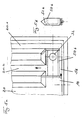
- Radiator assembly 10 comprises two plate-shaped radiators 12, 14.
- Each of the radiator panels 12, 14 includes an upper transverse channel 16 and a lower transverse channel 18, both of which are substantially parallel are arranged and run horizontally.
- Between the two Transverse channels 16, 18 is a variety of perpendicular to the transverse channels 16, 18 extending vertical channels 20 arranged.
- the heating water flows through a centrally arranged Connection 30 via a flow inlet 32 first in the lower transverse channel 18 of the first radiator 12, which serves as Bankwasservorlauf. From the central port 30 the heating water flows on both sides in the lower transverse channel 18 and then goes up in the vertical direction Vertical channels 20 headed, which at their upper end in the upper transverse channel 16 open.
- the heating water flows through a T-shaped connector 40b with valve insert 42, which is for regulation the heating water flow is used.
- the heating water flows over the connector 40b in the second plate-shaped Radiator 14, which corresponds to the first radiator 12 is formed.
- the heating water flows from the upper transverse channel 16 through the vertical channels 20 in the lower Cross channel from which the heating water to the central connection 30 out and derived via a return outlet 34 becomes.
- Connectors 40a, 40c, 40d arranged, which the same Structure as the connector 40b have. Indeed are the connecting pieces 40a, 40c, 40d with a Blanking plug shut off, allowing an overflow of heating water is prevented.
- For improved heat dissipation are on the insides of the two radiators 12, 14 in known Way Konvektorbleche 38 adapted.
- inserts in the vertical channels 20 provided in a central area 24, which in the area the central terminal 30 is located, and the adjoining areas are the vertical channels 20 free. These inserts form in the vertical channels 20 at least partially a cross-sectional reduction and thus increasing the flow resistance of the individual Vertical channels 20. This causes the heating water not, as usual, directly at the end regions 22a, 22b of the lower transverse channel 18 reinforced flows upwards. Rather, in these areas is through the inserts of the heating water flow diminishes, so that in the intermediate areas increased flow is trained.
- a functional insert 50a provided for a targeted heat emission is according to the embodiment of Fig. 4a and Figb in a lower transverse channel 18 at Central connection arrangement, a functional insert 50a provided.
- This insert 50a forms in the lower Cross channel 18 a separate inflow around the Opening of the feed inlet 32, so that the inflowing Heating water completely through the two connected to the channel Vertical channels 20 up to the not shown upper cross channel flows.
- FIG. 4b A cross-sectional view of the functional insert 50a is shown in Figure 4b, in particular the laterally arranged locking tongues 52a can be seen. These form with the impressions in the radiator plate a fit to the heating water in the desired manner to lead upwards.
- the functional insert 50a is smaller than the lower one Transverse channel 18 is formed so that between the lower wall the transverse channel 18 and the outside of the insert 50a a passageway 56 is formed. Through this can heating water, which from the vertical channels 20 again flows down, past the insert 50a in the direction of the connector to the subsequent Flow through the radiator plate.
- FIGS. 5a and 5b A similar embodiment, but for a lateral Connection can be seen in FIGS. 5a and 5b.
- a functional Insert 50b which with the wall of the radiator plate a defined channel around an opening of the flow inlet 32 forms, infiltrating heating water in seen from the right second vertical channel 20.2 of the radiator assembly.
- the insert 50b is designed so that There is a passage 56 in the lower transverse channel 18 leaves free, so that according to the indicated by arrows Flow direction heating water from the lower cross channel 18 to the first vertical channel 20.1 on the right side End of the radiator assembly can flow.
Claims (11)
- Système de radiateur avec au moins deux radiateurs (12, 14) en forme de plaques, dont au moins un radiateur (12) est conformé en arrivée d'eau chaude et un autre radiateur (14) est conformé en retour d'eau chaude, les radiateurs (12, 14) en forme de plaque (12, 14) présentant chacun un canal transversal supérieur (16) et un canal transversal inférieur (18) entre lesquels est prévue une pluralité de canaux verticaux (20) s'étendant pour l'essentiel verticalement,
caractérisé en ce qu 'afin d'uniformiser l'écoulement, des canaux verticaux (20) sont formés avec une résistance à l'écoulement différente de manière définie. - Système de radiateur selon la revendication 1, caractérisé en ce que les canaux verticaux latéraux (20) qui sont placés dans les parties d'extrémité (22) des canaux transversaux (8, 18) présentent une résistance à l'écoulement supérieure à celle des canaux verticaux (20) voisins.
- Système de radiateur selon la revendication 1 ou 2, caractérisé en ce que les canaux verticaux (20) qui sont placés dans une zone centrale (24) présentent une résistance à l'écoulement supérieure à celle des canaux verticaux (20) voisins.
- Système de radiateur selon l'une quelconque des revendications 1 à 3, caractérisé en ce que, pour obtenir une plus grande résistance à l'écoulement, la section d'écoulement du canal vertical (20) et/ou du canal transversal (15, 16) correspondant est réduite.
- Système de radiateur selon la revendication 4, caractérisé en ce que, pour réduire la section d'écoulement, au moins une pièce formant insert est placée dans le canal vertical (20) et/ou le canal transversal (16, 18), pièce qui présente de préférence simultanément la fonction d'une pièce de soutien.
- Système de radiateur selon l'une quelconque des revendications 1 à 5, caractérisé en ce que, pour réduire la section d'écoulement, des empreintes sont ménagées dans les parois des radiateurs (12,14) en forme de plaque.
- Système de radiateur selon l'une quelconque des revendications 1 à 6, caractérisé en ce qu 'un branchement (30) pour une entrée d'arrivée (32) et une prise de sortie (34) est prévu au niveau du canal transversal inférieur (18), en particulier latéralement et/ou au centre.
- Système de radiateur selon l'une quelconque des revendications 1 à 7, caractérisé en ce qu 'un raccord (40) avec boítier de vanne et insert de vanne (42) est placé entre deux canaux transversaux supérieurs (16).
- Système de radiateur selon l'une quelconque des revendications 1 à 8, caractérisé en ce qu 'au moins deux raccords (40) de même construction sont prévus, qui sont placés entre deux canaux transversaux supérieurs (16) et/ou inférieurs (18), et en ce que les raccords (40) peuvent être munis d'un élément enfichable (42) de vanne ou famés par lui.
- Système de radiateur selon l'une quelconque des revendications 1 à 9, caractérisé en ce qu 'une pièce formant insert (50) est placée dans l'un des canaux transversaux (18) au niveau d'une entrée d'arrivée (32), et en ce que l'eau d'arrivée peut être envoyée dans l'autre canal transversal (16) à travers la pièce formant insert (50).
- Système de radiateur selon l'une quelconque des revendications 1 à 10, caractérisé en ce qu 'une pièce formant insert (60) est placée dans l'un des canaux transversaux (16) au niveau d'un raccord (40) et en ce qu 'un débordement de l'eau chaude du canal transversal (16) vers le raccord (40) peut être évité par la pièce formant insert (60).
Applications Claiming Priority (2)
| Application Number | Priority Date | Filing Date | Title |
|---|---|---|---|
| DE20101345U | 2001-01-25 | ||
| DE20101345U DE20101345U1 (de) | 2001-01-25 | 2001-01-25 | Heizkörperanordnung |
Publications (2)
| Publication Number | Publication Date |
|---|---|
| EP1227290A1 EP1227290A1 (fr) | 2002-07-31 |
| EP1227290B1 true EP1227290B1 (fr) | 2004-03-10 |
Family
ID=7952088
Family Applications (1)
| Application Number | Title | Priority Date | Filing Date |
|---|---|---|---|
| EP01116046A Expired - Lifetime EP1227290B1 (fr) | 2001-01-25 | 2001-07-02 | Radiateur |
Country Status (3)
| Country | Link |
|---|---|
| EP (1) | EP1227290B1 (fr) |
| AT (1) | ATE261572T1 (fr) |
| DE (2) | DE20101345U1 (fr) |
Cited By (2)
| Publication number | Priority date | Publication date | Assignee | Title |
|---|---|---|---|---|
| DE202008007454U1 (de) | 2008-06-04 | 2008-07-31 | Kermi Gmbh | Heizkörper mit Teillastfunktion |
| DE102021203900A1 (de) | 2021-04-20 | 2022-10-20 | Kermi Gmbh | Ein- oder mehrreihiger Heizkörper |
Families Citing this family (5)
| Publication number | Priority date | Publication date | Assignee | Title |
|---|---|---|---|---|
| DE10113125A1 (de) * | 2001-03-17 | 2002-09-19 | Kermi Gmbh | Heizkörper mit einer mittig angeordneten Ventilgarnitur |
| DE10135215C1 (de) * | 2001-07-24 | 2002-07-25 | Berg Hans Gmbh & Co Kg | Plattenheizkörper |
| DE202005012826U1 (de) * | 2005-08-09 | 2005-10-20 | Kermi Gmbh | Heizkörper mit Teillastfunktion |
| DE202007010726U1 (de) * | 2007-07-31 | 2007-09-27 | Kermi Gmbh | Heizkörper mit Teillastfunktion |
| DE202007015143U1 (de) * | 2007-10-26 | 2007-12-27 | Kermi Gmbh | Heizkörper mit Teillastfunktion |
Family Cites Families (7)
| Publication number | Priority date | Publication date | Assignee | Title |
|---|---|---|---|---|
| FR2230953A1 (en) * | 1973-05-21 | 1974-12-20 | Paier Elie | Water circulation system for long radiator - differentially perforated discharge tube inside ensures even heat exchange |
| FI69516C (fi) * | 1977-11-17 | 1986-02-10 | Henningsson Ab Ing T | Varmvattenradiator |
| DE3216922C2 (de) * | 1982-05-06 | 1985-08-29 | Schäfer Werke GmbH, 5908 Neunkirchen | Einlegeteil für einen Plattenheizkörper |
| DE9412801U1 (de) | 1994-08-08 | 1994-10-06 | Koenig Christel | Heizkörperanordnung |
| DE19710069C2 (de) * | 1997-03-12 | 1999-08-19 | Buderus Heiztechnik Gmbh | Plattenheizkörper |
| DE19729633C2 (de) * | 1997-07-10 | 2003-04-17 | Kermi Gmbh | Ein- oder mehrreihiger Heizkörper mit zumindest zwei verschieden ausgelegten Abschnitten |
| DE19750624A1 (de) * | 1997-11-14 | 1999-05-20 | Kermi Gmbh | Systemheizkörper |
-
2001
- 2001-01-25 DE DE20101345U patent/DE20101345U1/de not_active Expired - Lifetime
- 2001-07-02 EP EP01116046A patent/EP1227290B1/fr not_active Expired - Lifetime
- 2001-07-02 AT AT01116046T patent/ATE261572T1/de not_active IP Right Cessation
- 2001-07-02 DE DE50101651T patent/DE50101651D1/de not_active Expired - Lifetime
Cited By (4)
| Publication number | Priority date | Publication date | Assignee | Title |
|---|---|---|---|---|
| DE202008007454U1 (de) | 2008-06-04 | 2008-07-31 | Kermi Gmbh | Heizkörper mit Teillastfunktion |
| EP2131118A1 (fr) | 2008-06-04 | 2009-12-09 | KERMI GmbH | Radiateur doté d'une fonction de charge partielle |
| DE102021203900A1 (de) | 2021-04-20 | 2022-10-20 | Kermi Gmbh | Ein- oder mehrreihiger Heizkörper |
| WO2022223158A1 (fr) | 2021-04-20 | 2022-10-27 | Kermi Gmbh | Élément chauffant à une ou plusieurs rangées |
Also Published As
| Publication number | Publication date |
|---|---|
| DE50101651D1 (de) | 2004-04-15 |
| EP1227290A1 (fr) | 2002-07-31 |
| ATE261572T1 (de) | 2004-03-15 |
| DE20101345U1 (de) | 2001-03-29 |
Similar Documents
| Publication | Publication Date | Title |
|---|---|---|
| DE10292792B4 (de) | Klimatisierungskanal für ein Fahrzeug | |
| DE19709601C5 (de) | Plattenwärmeübertrager | |
| EP1227290B1 (fr) | Radiateur | |
| WO2005080698A1 (fr) | Dispositif d'evacuation sanitaire | |
| DE3709970C2 (fr) | ||
| DE1931304U (de) | Luftverteiler. | |
| AT4175U1 (de) | Verschliessbarer kühlergrill für kraftfahrzeuge | |
| EP0360147B1 (fr) | Boucle à écoulement en spirales | |
| EP0162993B1 (fr) | Tour de réfrigération humide ou combinée par voies humides et sèches | |
| WO1999036241A1 (fr) | Noyau refrigerant et chauffant | |
| EP0816772B1 (fr) | Sortie d'air | |
| CH691621A5 (de) | Mattenartiger Wärmetauscher für Kühl- und/oder Heizzwecke. | |
| EP1553363B1 (fr) | Ensemble collecteur pour radiateurs de chauffage ou de réfrigeration | |
| EP0052717A1 (fr) | Distributeur pour chauffage central | |
| EP2619022B1 (fr) | Élément mélangeur et module mélangeur de deux flux d'air se croisant dans un appareil de climatisation | |
| EP2171365B1 (fr) | Radiateur à fonction de charge partielle | |
| EP1243870A2 (fr) | Radiateur | |
| AT506080A4 (de) | Installations-montagemodul | |
| EP2171366A1 (fr) | Radiateur pourvu d'une fonction de charge partielle | |
| EP1561615B1 (fr) | Echangeur de chaleur | |
| DE10004903B4 (de) | Plattenheizkörper | |
| DE202011107258U1 (de) | Lufttechnisches Induktionsgerät | |
| DE10039405A1 (de) | Rohrheizkörper | |
| CH659879A5 (en) | Weather-protection grating for ducts opening in external walls | |
| DE19912567A1 (de) | Luftleiteinrichtung für einen Luftdurchlaß |
Legal Events
| Date | Code | Title | Description |
|---|---|---|---|
| PUAI | Public reference made under article 153(3) epc to a published international application that has entered the european phase |
Free format text: ORIGINAL CODE: 0009012 |
|
| 17P | Request for examination filed |
Effective date: 20020404 |
|
| AK | Designated contracting states |
Kind code of ref document: A1 Designated state(s): AT BE CH CY DE DK ES FI FR GB GR IE IT LI LU MC NL PT SE TR |
|
| AX | Request for extension of the european patent |
Free format text: AL;LT;LV;MK;RO;SI |
|
| 17Q | First examination report despatched |
Effective date: 20020927 |
|
| REG | Reference to a national code |
Ref country code: GB Ref legal event code: FG4D Free format text: NOT ENGLISH |
|
| GRAH | Despatch of communication of intention to grant a patent |
Free format text: ORIGINAL CODE: EPIDOS IGRA |
|
| AKX | Designation fees paid |
Designated state(s): AT BE CH CY DE DK ES FI FR GB GR IE IT LI LU MC NL PT SE TR |
|
| GRAS | Grant fee paid |
Free format text: ORIGINAL CODE: EPIDOSNIGR3 |
|
| GRAA | (expected) grant |
Free format text: ORIGINAL CODE: 0009210 |
|
| AK | Designated contracting states |
Kind code of ref document: B1 Designated state(s): AT BE CH CY DE DK ES FI FR GB GR IE IT LI LU MC NL PT SE TR |
|
| PG25 | Lapsed in a contracting state [announced via postgrant information from national office to epo] |
Ref country code: CY Free format text: LAPSE BECAUSE OF FAILURE TO SUBMIT A TRANSLATION OF THE DESCRIPTION OR TO PAY THE FEE WITHIN THE PRESCRIBED TIME-LIMIT Effective date: 20040310 Ref country code: IE Free format text: LAPSE BECAUSE OF FAILURE TO SUBMIT A TRANSLATION OF THE DESCRIPTION OR TO PAY THE FEE WITHIN THE PRESCRIBED TIME-LIMIT Effective date: 20040310 Ref country code: FI Free format text: LAPSE BECAUSE OF FAILURE TO SUBMIT A TRANSLATION OF THE DESCRIPTION OR TO PAY THE FEE WITHIN THE PRESCRIBED TIME-LIMIT Effective date: 20040310 Ref country code: TR Free format text: LAPSE BECAUSE OF FAILURE TO SUBMIT A TRANSLATION OF THE DESCRIPTION OR TO PAY THE FEE WITHIN THE PRESCRIBED TIME-LIMIT Effective date: 20040310 |
|
| REG | Reference to a national code |
Ref country code: CH Ref legal event code: EP |
|
| REG | Reference to a national code |
Ref country code: IE Ref legal event code: FG4D Free format text: GERMAN |
|
| REF | Corresponds to: |
Ref document number: 50101651 Country of ref document: DE Date of ref document: 20040415 Kind code of ref document: P |
|
| PG25 | Lapsed in a contracting state [announced via postgrant information from national office to epo] |
Ref country code: SE Free format text: LAPSE BECAUSE OF FAILURE TO SUBMIT A TRANSLATION OF THE DESCRIPTION OR TO PAY THE FEE WITHIN THE PRESCRIBED TIME-LIMIT Effective date: 20040610 Ref country code: GR Free format text: LAPSE BECAUSE OF FAILURE TO SUBMIT A TRANSLATION OF THE DESCRIPTION OR TO PAY THE FEE WITHIN THE PRESCRIBED TIME-LIMIT Effective date: 20040610 Ref country code: DK Free format text: LAPSE BECAUSE OF FAILURE TO SUBMIT A TRANSLATION OF THE DESCRIPTION OR TO PAY THE FEE WITHIN THE PRESCRIBED TIME-LIMIT Effective date: 20040610 |
|
| PG25 | Lapsed in a contracting state [announced via postgrant information from national office to epo] |
Ref country code: ES Free format text: LAPSE BECAUSE OF FAILURE TO SUBMIT A TRANSLATION OF THE DESCRIPTION OR TO PAY THE FEE WITHIN THE PRESCRIBED TIME-LIMIT Effective date: 20040621 |
|
| PG25 | Lapsed in a contracting state [announced via postgrant information from national office to epo] |
Ref country code: LU Free format text: LAPSE BECAUSE OF NON-PAYMENT OF DUE FEES Effective date: 20040702 |
|
| PG25 | Lapsed in a contracting state [announced via postgrant information from national office to epo] |
Ref country code: MC Free format text: LAPSE BECAUSE OF NON-PAYMENT OF DUE FEES Effective date: 20040731 |
|
| GBT | Gb: translation of ep patent filed (gb section 77(6)(a)/1977) |
Effective date: 20040708 |
|
| REG | Reference to a national code |
Ref country code: IE Ref legal event code: FD4D |
|
| ET | Fr: translation filed | ||
| PLBE | No opposition filed within time limit |
Free format text: ORIGINAL CODE: 0009261 |
|
| STAA | Information on the status of an ep patent application or granted ep patent |
Free format text: STATUS: NO OPPOSITION FILED WITHIN TIME LIMIT |
|
| 26N | No opposition filed |
Effective date: 20041213 |
|
| PG25 | Lapsed in a contracting state [announced via postgrant information from national office to epo] |
Ref country code: LI Free format text: LAPSE BECAUSE OF NON-PAYMENT OF DUE FEES Effective date: 20050731 Ref country code: CH Free format text: LAPSE BECAUSE OF NON-PAYMENT OF DUE FEES Effective date: 20050731 |
|
| PGFP | Annual fee paid to national office [announced via postgrant information from national office to epo] |
Ref country code: GB Payment date: 20050810 Year of fee payment: 5 |
|
| PGFP | Annual fee paid to national office [announced via postgrant information from national office to epo] |
Ref country code: NL Payment date: 20050815 Year of fee payment: 5 |
|
| PGFP | Annual fee paid to national office [announced via postgrant information from national office to epo] |
Ref country code: AT Payment date: 20050825 Year of fee payment: 5 Ref country code: BE Payment date: 20050825 Year of fee payment: 5 |
|
| PGFP | Annual fee paid to national office [announced via postgrant information from national office to epo] |
Ref country code: FR Payment date: 20050830 Year of fee payment: 5 |
|
| REG | Reference to a national code |
Ref country code: CH Ref legal event code: PL |
|
| PG25 | Lapsed in a contracting state [announced via postgrant information from national office to epo] |
Ref country code: GB Free format text: LAPSE BECAUSE OF NON-PAYMENT OF DUE FEES Effective date: 20060702 Ref country code: AT Free format text: LAPSE BECAUSE OF NON-PAYMENT OF DUE FEES Effective date: 20060702 |
|
| PG25 | Lapsed in a contracting state [announced via postgrant information from national office to epo] |
Ref country code: BE Free format text: LAPSE BECAUSE OF NON-PAYMENT OF DUE FEES Effective date: 20060731 |
|
| PGFP | Annual fee paid to national office [announced via postgrant information from national office to epo] |
Ref country code: IT Payment date: 20060731 Year of fee payment: 6 |
|
| PG25 | Lapsed in a contracting state [announced via postgrant information from national office to epo] |
Ref country code: NL Free format text: LAPSE BECAUSE OF NON-PAYMENT OF DUE FEES Effective date: 20070201 |
|
| GBPC | Gb: european patent ceased through non-payment of renewal fee |
Effective date: 20060702 |
|
| NLV4 | Nl: lapsed or anulled due to non-payment of the annual fee |
Effective date: 20070201 |
|
| REG | Reference to a national code |
Ref country code: FR Ref legal event code: ST Effective date: 20070330 |
|
| BERE | Be: lapsed |
Owner name: *KONIG CHRISTEL Effective date: 20060731 |
|
| PG25 | Lapsed in a contracting state [announced via postgrant information from national office to epo] |
Ref country code: PT Free format text: LAPSE BECAUSE OF NON-PAYMENT OF DUE FEES Effective date: 20040810 |
|
| PG25 | Lapsed in a contracting state [announced via postgrant information from national office to epo] |
Ref country code: FR Free format text: LAPSE BECAUSE OF NON-PAYMENT OF DUE FEES Effective date: 20060731 |
|
| PG25 | Lapsed in a contracting state [announced via postgrant information from national office to epo] |
Ref country code: IT Free format text: LAPSE BECAUSE OF NON-PAYMENT OF DUE FEES Effective date: 20070702 |
|
| REG | Reference to a national code |
Ref country code: DE Ref legal event code: R082 Ref document number: 50101651 Country of ref document: DE Representative=s name: WUNDERLICH & HEIM PATENTANWAELTE PARTNERSCHAFT, DE |
|
| PGFP | Annual fee paid to national office [announced via postgrant information from national office to epo] |
Ref country code: DE Payment date: 20200207 Year of fee payment: 20 |
|
| REG | Reference to a national code |
Ref country code: DE Ref legal event code: R071 Ref document number: 50101651 Country of ref document: DE |