EP1553363B1 - Ensemble collecteur pour radiateurs de chauffage ou de réfrigeration - Google Patents
Ensemble collecteur pour radiateurs de chauffage ou de réfrigeration Download PDFInfo
- Publication number
- EP1553363B1 EP1553363B1 EP05008269A EP05008269A EP1553363B1 EP 1553363 B1 EP1553363 B1 EP 1553363B1 EP 05008269 A EP05008269 A EP 05008269A EP 05008269 A EP05008269 A EP 05008269A EP 1553363 B1 EP1553363 B1 EP 1553363B1
- Authority
- EP
- European Patent Office
- Prior art keywords
- hollow
- heating
- plates
- plate
- cooling body
- Prior art date
- Legal status (The legal status is an assumption and is not a legal conclusion. Google has not performed a legal analysis and makes no representation as to the accuracy of the status listed.)
- Expired - Lifetime
Links
Images


Classifications
-
- F—MECHANICAL ENGINEERING; LIGHTING; HEATING; WEAPONS; BLASTING
- F24—HEATING; RANGES; VENTILATING
- F24D—DOMESTIC- OR SPACE-HEATING SYSTEMS, e.g. CENTRAL HEATING SYSTEMS; DOMESTIC HOT-WATER SUPPLY SYSTEMS; ELEMENTS OR COMPONENTS THEREFOR
- F24D19/00—Details
- F24D19/0002—Means for connecting central heating radiators to circulation pipes
- F24D19/0017—Connections between supply and inlet or outlet of central heating radiators
- F24D19/0024—Connections for plate radiators
-
- F—MECHANICAL ENGINEERING; LIGHTING; HEATING; WEAPONS; BLASTING
- F28—HEAT EXCHANGE IN GENERAL
- F28D—HEAT-EXCHANGE APPARATUS, NOT PROVIDED FOR IN ANOTHER SUBCLASS, IN WHICH THE HEAT-EXCHANGE MEDIA DO NOT COME INTO DIRECT CONTACT
- F28D1/00—Heat-exchange apparatus having stationary conduit assemblies for one heat-exchange medium only, the media being in contact with different sides of the conduit wall, in which the other heat-exchange medium is a large body of fluid, e.g. domestic or motor car radiators
- F28D1/02—Heat-exchange apparatus having stationary conduit assemblies for one heat-exchange medium only, the media being in contact with different sides of the conduit wall, in which the other heat-exchange medium is a large body of fluid, e.g. domestic or motor car radiators with heat-exchange conduits immersed in the body of fluid
- F28D1/03—Heat-exchange apparatus having stationary conduit assemblies for one heat-exchange medium only, the media being in contact with different sides of the conduit wall, in which the other heat-exchange medium is a large body of fluid, e.g. domestic or motor car radiators with heat-exchange conduits immersed in the body of fluid with plate-like or laminated conduits
- F28D1/0308—Heat-exchange apparatus having stationary conduit assemblies for one heat-exchange medium only, the media being in contact with different sides of the conduit wall, in which the other heat-exchange medium is a large body of fluid, e.g. domestic or motor car radiators with heat-exchange conduits immersed in the body of fluid with plate-like or laminated conduits the conduits being formed by paired plates touching each other
-
- F—MECHANICAL ENGINEERING; LIGHTING; HEATING; WEAPONS; BLASTING
- F28—HEAT EXCHANGE IN GENERAL
- F28F—DETAILS OF HEAT-EXCHANGE AND HEAT-TRANSFER APPARATUS, OF GENERAL APPLICATION
- F28F9/00—Casings; Header boxes; Auxiliary supports for elements; Auxiliary members within casings
- F28F9/26—Arrangements for connecting different sections of heat-exchange elements, e.g. of radiators
- F28F9/262—Arrangements for connecting different sections of heat-exchange elements, e.g. of radiators for radiators
Definitions
- the present invention relates to a heating or cooling body of the type, as referred to by the preamble of patent claim 1.
- the invention relates to convection heating or cooling bodies, which are also called convectors in the following.
- Such convectors which usually have one or more parallel heating plates, which in turn are formed from substantially horizontally extending hollow plates (flat heating tubes), direct the heating or cooling agent from a flow connection via the hollow plates to a return connection, wherein on the heating plate or between several heating plates are usually convector blades that form convection chimneys to dissipate the heated or cooled air in a particular direction (usually up or down) and thereby produce a continuous heat exchange through the air flow.
- flexible installation options should be created and a visually appealing construction should be made possible.
- the inventive design of the distribution of the heating or cooling medium in the convector body advantageously provides the opportunity to put the flow and return connections as desired at different points of the heating or cooling body.
- the arrangement of separate distribution channels, as proposed according to the invention further increases the flexibility in the design possibilities for a convector body.
- a particularly compact arrangement can be achieved if the feed connection is connected via a through the return passage of a first distribution channel extending therethrough to the flow section of a separate distribution channel.
- An externally appealing appearance is provided according to the invention when the vertical end faces of the convector body have substantially rectangular, separate distribution channels which provide a lateral termination.
- the supply and return connections of a convector body according to the invention can according to the invention open directly or via a section of a distribution channel into an upper, but also into a lower divided hollow plate and then be connected further via the distributor arrangement and the other hollow plates.
- the invention further relates to a spacer, which is used in particular for the production of hollow plates for a heating or cooling body.
- spacers In the preparation of the hollow tubes configured as rectangular tubes spacers must be inserted between the flat portions of the hollow plates to be bent to each other be used to prevent the cavity is pressed during processing.
- round discs are used in the prior art, have the flow openings. However, such round discs are critical in that they may slip during the manufacturing process and thus can no longer maintain their function as spacers.
- the invention solves the above problem by providing a spacer having an attachable part which can be attached to the front side of the hollow plate sections and spacers projecting therefrom, which project into the cavity of the hollow plates and in particular have a height substantially equal to the internal spacing of the hollow plate parts.
- the spacers according to the invention form with their Anöneil the frontal closure of the hollow plates and thus immovably arranged, the projecting spacers are automatically arranged immovable, so that in the production no disturbances due to shifted spacers are more to be feared.
- At least one, preferably two fork-like, protruding spacer strips protrude from a plate which is in the form of an attachment part and which is substantially flat and corresponds to the end cross-section of the hollow plate.
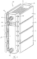
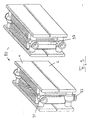
- Fig. 1 shows a convector radiator of a first embodiment according to the present invention in an exploded perspective view, while Fig. 2 illustrates this radiator in the assembled state.
- the radiator according to this first embodiment is provided overall with the reference numeral 10.
- the convector body 10 has on each of its flat sides four hollow plates 1, 2, 3 and 4, which transport a heating medium as flat heating tubes. Between Hollow plates are arranged convector blades 5, which form chimneys for the convective air passage.
- the convector body 10 has the distribution channel 12, while at the rear end side of the distribution channel 17 is mounted.
- the two distribution channels are connected via the connecting tube 16 with the hollow plates 1 to 4 in each case in the frontal region in connection.
- the attachment between the connecting tube 16 and the connection points on the hollow plates can be realized for example by resistance welding.
- the rectangular distribution channel 12 is divided by a horizontally extending web into two sections, namely a forward section 14 and a return section 15. This can be clearly seen in the cut-away area of FIG. 1.
- the distribution channel 17, however, is formed as a continuous rectangular tube.
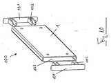
- FIG. 3 A particularly compact embodiment of a convector body 20 with a bottom-side supply connection is shown in FIG.
- Fig. 3 and in the further also for Figs. 4 to 9 is that the same reference numerals or reference numerals denote with identical last digits components corresponding to those in Figs. 1 and 2.
- the convector body 20 of Fig. 3, with the exception of the manifold 22 has the same structure as that of Figs. 1 and 2, and he also has the same flow guide except for this difference.
- the convector body 20 is a radiator with a bottom-side flow connection 21.
- This bottom-side flow connection 21 passes as a tube through the return section 25 of the distribution channel 22 and opens up in the flow section 24, from where the heating medium is then in turn passed to the top hollow plate 1.
- the flow pattern is the same as the convector body 10, i. the heating medium flows via the hollow plates 2, 3 and 4 back into the return section 25 and exits from the return port 23.
- With the implementation of the flow pipe 28 through the return section 25 space is saved in the interior of the radiator and it can, for. B. more slats 5 are arranged.
- the upper port 21 'in the flow section 24 can either be blind flanged or provided with a vent.
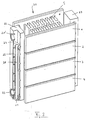
- FIG. 4 shows a front and a rear end perspective view of a convector body 30 according to a third embodiment.
- This convector body 30 has at the connection end face shown on the left a running only on the lower hollow plates 2, 3 and 4 rectangular distribution channel 32, which forms a total of only one return section.
- a rectangular distribution channel 37 extends over all hollow plates.
- the convector body 30 shown here is a radiator which has on the bottom side both the flow connection 38 and the return connection 33.
- the flow connection 38 leads as a pipe up to a commonly used fitting, which distributes the heating medium on both sides of the first hollow plate 1.
- two ports are provided on the distribution channel 37, of which the lower port 39 can be used as a further return port, while at the unspecified upper port, for example, a vent valve can be attached.
- valve in this case forms part of the convector body and is in particular clad accordingly.
- a similar convector radiator 40 is shown in FIG. 5.
- the difference to the Konvektörissonson 30 of FIG. 4 is that on the port side shown on the left side of the distribution channel 42 extends over all four hollow plates. Also, this distribution channel 42 is separated below the top hollow plate by a not visible here separation device. From the feed connection 48, a pipe leads behind the distribution channel 42 in its upper flow region, while the return connection 43 is provided at the bottom of the distribution channel 42. As can be seen from the diagram on the right, a return 49 as well as a ventilation connection at the top can also be provided here again on the opposite end side.
- the above embodiment may also be configured as a convector heater having a center port.
- FIG. 6 an alternative embodiment of a convector radiator according to the invention is now shown.
- This radiator has (on both sides) a divided lower hollow plate with a flow side 4a and a return side 4b.
- the two illustrations in Fig. 6 show the same radiator 50; the upper illustration is only slightly tilted to make the flow port 58 and the return port 59 visible.
- the flow guide is in this radiator the following (see also the arrows): Through the feed port 58, the heating medium enters the first half-shell half (lead half) 4a and is introduced from there via the distribution channel 52 in the upper hollow plates 1, 2 and 3, where it flows opposite to the direction indicated on the hollow plate half 4a.
- the distribution channel 52 is not divided, ie in this embodiment, the role of the separate lead section (see Fig. 1, reference numeral 14) is taken over by the hollow plate half 4a itself.
- the heating medium After flowing through the hollow plates 1, 2 and 3, the heating medium enters the rear manifold 57 and is directed from there down into the hollow plate half 4b, which forms a return half.
- the return port 59 is connected to the hollow plate half 4b and passes the heating medium back out of the radiator.
- FIG. 7 corresponds to the embodiment shown in FIG. 6 with regard to the basic flow guidance.
- the radiator 60 of FIG. 7, however, is a radiator with three heating plates, which are each formed of continuous hollow plates 1, 2 and 3.
- the lower hollow plate of the front heating plate is in turn divided into the flow and return halves 4a and 4b, so that the already discussed with reference to FIG. 6 flow is achieved.
- the radiator 60 instead of the rectangular distribution channels pipe distributor 62 and 67 with conventional fittings. Also, this radiator 60 has the bottom connections 68 (flow) and 69 (return).
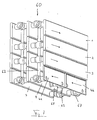
- FIG. 8 again shows an embodiment of a heating element 80, which corresponds with respect to the flow guide to that shown in Fig. 1.
- This radiator 80 differs from the radiator 10 shown in FIG. 1 in that Instead of the rectangular distribution channels now pipe manifold 82 and 87 are used.
- the return section 82 has a downwardly outgoing return port 83 and extends to return the heating medium through the three lower hollow plates 2, 3 and 4.
- the rear manifold 87 all four hollow plates 1 to 4 connects with each other.
- the embodiment of the radiator 90 according to FIG. 9 corresponds in principle completely to that shown in FIG. 8, with the difference that the radiator shown here has only two superimposed hollow plates 1 and 2 on each side.
- the heating medium flows from the feed connection 91 through the hollow plate 1 and is passed via the return pipe manifold 97 through the hollow plate 2 back to the return port 93, which in turn goes down to the ground.
- the heating tube spacer assembly is designated by reference numeral 100. It consists of an already curved in shape hollow plate piece 1 and the spacers, which have a closure plate 101 and fork-like spacers 102.
- the end plates 101 are adapted or attached during manufacture to the end faces of the hollow plate 1, so that the fork-like spacers 102 penetrate into the cavity 103 and can serve as a spacer for the two lateral plates of the hollow plate 1. These spacers can neither slip nor block the flow through the hollow plate. 1
- FIG. 11 shows a further training possibility for the adjacent hollow plates.
- the hollow plates 1, 2 and 3 of the upper illustration and the two hollow plates 1 and 2 in the lower illustration were produced by rolling with the aid of profile rollers in the form of closed heating registers.
- the adjacent part A at a pitch of the hollow plate sections of about 70 mm has a width of about 10 mm.
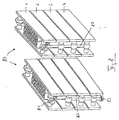
- Figures 12 and 13 illustrate a half shell construction of a convector body.
- the convector body is shown in perspective view in different sectional planes I, II and III.
- the representation I shows the convector body in half shell construction with the numbered from top to bottom flow channels 1 to 5 uncut.
- the front part of the convector body is cut away in the region of the connections, while the illustration III shows a convector body cut a little further back.
- heating plates which are composed of a front half-shell V and a rear half-shell H.
- the front half-shell V has the convexly curved flow channels 1 to 5, while in the rear half-shell H overflow channels U are provided which forward the heating medium at suitable locations from one flow channel to the other.
- overflow channels U are also designated in FIG. 12, it being apparent in section III that at the locations where the overflow channels U are present, the heating medium can pass from a flow channel into an adjacent flow channel.
- the desired flow guidance can be generated, in particular a flow guide, as previously described with reference to the previously illustrated embodiments.
Landscapes
- Engineering & Computer Science (AREA)
- General Engineering & Computer Science (AREA)
- Thermal Sciences (AREA)
- Mechanical Engineering (AREA)
- Physics & Mathematics (AREA)
- Chemical & Material Sciences (AREA)
- Combustion & Propulsion (AREA)
- Steam Or Hot-Water Central Heating Systems (AREA)
- Domestic Hot-Water Supply Systems And Details Of Heating Systems (AREA)
- Heat-Exchange Devices With Radiators And Conduit Assemblies (AREA)
- Cooling Or The Like Of Electrical Apparatus (AREA)
- Resistance Heating (AREA)
- Cooling Or The Like Of Semiconductors Or Solid State Devices (AREA)
- Physical Or Chemical Processes And Apparatus (AREA)
Claims (6)
- Radiateur de chauffage ou de réfrigération avec des conduites ou des plaques creuses orientées sensiblement à l'horizontale, un raccord d'arrivée (11) et un raccord de retour (13) ainsi qu'un ensemble collecteur pour le fluide de chauffage ou de réfrigération,a) dans lequel le raccord d'arrivée est raccordé à un côté d'entrée d'une première conduite ou plaque creuse (1, 4a) qui conduit le fluide de chauffage ou de réfrigération vers l'aval, par son côté de sortie, dans l'ensemble collecteur, d'où il est renvoyé par les conduites ou plaques creuses restantes vers le raccord de retour,b) dans lequel l'ensemble collecteur comporte des canaux collecteurs séparés (12, 17) sensiblement rectangulaires dont un (12) est divisé en section d'arrivée et section de retour (14, 15) séparées l'une de l'autre, la section d'arrivée (14) étant connectée à la zone d'entrée de la première conduite ou plaque creuse (1), etc) dans lequel le raccord d'arrivée (48) est raccordé à la section d'arrivée par un tube s'étendant à côté de la section de retour du premier canal collecteur (42)
caractérisé en ce qued) l'ensemble collecteur est réalisé sous la forme d'un capot fermant sensiblement frontalement le radiateur de chauffage ou de réfrigération. - Radiateur de chauffage ou de réfrigération selon la revendication 1, caractérisé en ce que la première plaque creuse (1) est une plaque creuse supérieure, en particulier la plaque creuse la plus haute, d'un côté du radiateur de chauffage ou de réfrigération.
- Radiateur de chauffage ou de réfrigération selon l'une des revendications précédentes, caractérisé en ce que les conduites ou plaques creuses sont disposées en face l'une de l'autre en un radiateur de chauffage ou de réfrigération à double face.
- Radiateur de chauffage selon l'une des revendications précédentes, caractérisé en ce que des lamelles de convecteur (5), qui forment de préférence des cheminées de convection, sont disposées sur les plaques creuses ou entre deux plaques creuses disposées en face l'une de l'autre.
- Radiateur de chauffage ou de réfrigération selon l'une des revendications précédentes, caractérisé en ce qu'il comprend au moins un élément d'écartement pour la fabrication de plaques creuses (1), dans lequel le au moins un élément d'écartement présente une pièce rapportée (101) applicable sur le côté frontal des sections de plaque creuse, et des pièces d'écartement (102) saillantes sur celle-ci, qui pénètrent dans l'espace creux (103) des plaques creuses et ont en particulier une hauteur qui correspond sensiblement à la distance nominale entre les parties de plaque creuse.
- Radiateur de chauffage ou de réfrigération selon la revendication précédente, caractérisé en ce qu'au moins une, de préférence deux bandes d'écartement (102) saillantes en forme de fourche sont saillantes sur une plaque (101) du au moins un élément d'écartement réalisé sous la forme d'une pièce rapportée, sensiblement plate et correspondant à la forme de la section frontale des plaques creuses.
Applications Claiming Priority (3)
| Application Number | Priority Date | Filing Date | Title |
|---|---|---|---|
| DE19832051A DE19832051C2 (de) | 1998-07-16 | 1998-07-16 | Heiz- bzw. Kühlkörper-Verteileranordnung |
| DE19832051 | 1998-07-16 | ||
| EP99113520A EP0972998B1 (fr) | 1998-07-16 | 1999-07-05 | Ensemble collecteur pour radiateurs de chauffage ou de réfrigeration |
Related Parent Applications (1)
| Application Number | Title | Priority Date | Filing Date |
|---|---|---|---|
| EP99113520A Division EP0972998B1 (fr) | 1998-07-16 | 1999-07-05 | Ensemble collecteur pour radiateurs de chauffage ou de réfrigeration |
Publications (2)
| Publication Number | Publication Date |
|---|---|
| EP1553363A1 EP1553363A1 (fr) | 2005-07-13 |
| EP1553363B1 true EP1553363B1 (fr) | 2007-01-03 |
Family
ID=7874322
Family Applications (2)
| Application Number | Title | Priority Date | Filing Date |
|---|---|---|---|
| EP99113520A Expired - Lifetime EP0972998B1 (fr) | 1998-07-16 | 1999-07-05 | Ensemble collecteur pour radiateurs de chauffage ou de réfrigeration |
| EP05008269A Expired - Lifetime EP1553363B1 (fr) | 1998-07-16 | 1999-07-05 | Ensemble collecteur pour radiateurs de chauffage ou de réfrigeration |
Family Applications Before (1)
| Application Number | Title | Priority Date | Filing Date |
|---|---|---|---|
| EP99113520A Expired - Lifetime EP0972998B1 (fr) | 1998-07-16 | 1999-07-05 | Ensemble collecteur pour radiateurs de chauffage ou de réfrigeration |
Country Status (3)
| Country | Link |
|---|---|
| EP (2) | EP0972998B1 (fr) |
| AT (2) | ATE350628T1 (fr) |
| DE (3) | DE19832051C2 (fr) |
Families Citing this family (4)
| Publication number | Priority date | Publication date | Assignee | Title |
|---|---|---|---|---|
| DE10113125A1 (de) * | 2001-03-17 | 2002-09-19 | Kermi Gmbh | Heizkörper mit einer mittig angeordneten Ventilgarnitur |
| DE102006001618A1 (de) * | 2006-01-11 | 2007-07-12 | Arbonia Ag | Radiator mit flachen Rohrelementen und Verfahren zu dessen Herstellung |
| DE102013218369A1 (de) * | 2013-09-13 | 2015-03-19 | Hans-Alfred Balg | Niedrigst-Energie-Heizkörper |
| CZ32005U1 (cs) * | 2018-03-12 | 2018-08-28 | Korado, A.S. | Univerzální otopné těleso |
Family Cites Families (11)
| Publication number | Priority date | Publication date | Assignee | Title |
|---|---|---|---|---|
| CH341292A (de) * | 1955-08-17 | 1959-09-30 | Runtal Holding Co Sa | Verfahren zur Herstellung von Heizwänden sowie nach diesem Verfahren hergestellte Heizwand |
| CH436191A (fr) * | 1965-08-03 | 1967-05-31 | Runtal Holding Co Sa | Procédé de fabrication d'un radiateur de chauffage ou de refroidissement et radiateur fabriqué d'après ce procédé |
| CH431872A (de) * | 1965-11-17 | 1967-03-15 | Zehnder Ag Geb | Zentralheizungsradiator |
| DE2315737A1 (de) * | 1973-03-27 | 1974-10-10 | Liedelt Kg D F | Heizkoerper fuer einrohrheizungsanlagen |
| CH654100A5 (de) * | 1981-03-12 | 1986-01-31 | Runtal Holding Co Sa | Heizkoerper. |
| CH683126A5 (de) * | 1991-06-25 | 1994-01-14 | Runtal Holding Co Sa | Heizrohr zur Bildung einer Heizwand. |
| DE9412801U1 (de) * | 1994-08-08 | 1994-10-06 | König, Christel, 63674 Altenstadt | Heizkörperanordnung |
| FR2738907B1 (fr) * | 1995-09-15 | 1997-12-05 | Finimetal Societe De Finissage | Dispositif de raccordement universel pour radiateur tubulaire |
| DE19535280C2 (de) * | 1995-09-22 | 1999-08-26 | Koenig | Heizkörperanordnung |
| DE29705694U1 (de) * | 1996-04-09 | 1997-06-26 | Vogel & Noot Wärmetechnik AG, Wartberg | Konvektor, Konvektorrohling und Konvektorbausatz |
| DE29617392U1 (de) * | 1996-10-07 | 1996-11-21 | Agotech AG, Schönenwerd | Konvektorheizkörper mit Wärmeabstrahlschutz |
-
1998
- 1998-07-16 DE DE19832051A patent/DE19832051C2/de not_active Expired - Fee Related
-
1999
- 1999-07-05 AT AT05008269T patent/ATE350628T1/de not_active IP Right Cessation
- 1999-07-05 AT AT99113520T patent/ATE303564T1/de not_active IP Right Cessation
- 1999-07-05 EP EP99113520A patent/EP0972998B1/fr not_active Expired - Lifetime
- 1999-07-05 EP EP05008269A patent/EP1553363B1/fr not_active Expired - Lifetime
- 1999-07-05 DE DE59914130T patent/DE59914130D1/de not_active Expired - Fee Related
- 1999-07-05 DE DE59912483T patent/DE59912483D1/de not_active Expired - Fee Related
Also Published As
| Publication number | Publication date |
|---|---|
| EP0972998A2 (fr) | 2000-01-19 |
| DE19832051C2 (de) | 2002-06-13 |
| EP1553363A1 (fr) | 2005-07-13 |
| DE59914130D1 (de) | 2007-02-15 |
| ATE303564T1 (de) | 2005-09-15 |
| EP0972998A3 (fr) | 2002-08-07 |
| DE19832051A1 (de) | 2000-01-20 |
| ATE350628T1 (de) | 2007-01-15 |
| EP0972998B1 (fr) | 2005-08-31 |
| DE59912483D1 (de) | 2005-10-06 |
Similar Documents
| Publication | Publication Date | Title |
|---|---|---|
| DE2441652C3 (de) | Rippenrohr-Wärmetauscher | |
| EP1643202B1 (fr) | Echangeur de chaleur | |
| DE102005019578A1 (de) | Vorrichtung zum Heizen durch Fluidzirkulation | |
| DE4441503A1 (de) | Wärmetauscher, insbesondere für Kraftfahrzeuge | |
| DE10248665A1 (de) | Wärmeübertrager in Serpentinenbauweise | |
| DE102005059920B4 (de) | Wärmetauscher, insbesondere Verdampfer | |
| EP1553363B1 (fr) | Ensemble collecteur pour radiateurs de chauffage ou de réfrigeration | |
| DE102005048838A1 (de) | Wärmetauscher | |
| EP1593536B1 (fr) | Procédé et dispositif pour séparer l'écoulement de fluides dans un dispositif de chauffage | |
| DE19638714A1 (de) | Mattenartiger Wärmetauscher für Kühl- und/oder Heizzwecke | |
| EP1227290B1 (fr) | Radiateur | |
| WO2008003291A1 (fr) | Élément chauffant, en particulier radiateur à tubes | |
| DE2440184A1 (de) | Ausgestaltung eines gliedes aus stahlblech fuer einen heizungsradiator | |
| EP0816772B1 (fr) | Sortie d'air | |
| DE3229757C2 (de) | Profilrohr für Wärmetauscher, insbesondere für Raumheizkörper | |
| DE19535280C2 (de) | Heizkörperanordnung | |
| DE102017204492A1 (de) | Wärmetauscher für eine Schmelzflusselektrolysezelle | |
| EP3499167B1 (fr) | Dispositif de mise en température d'un espace ainsi que procédé de son fabrication | |
| DE102007035817B4 (de) | Röhrenradiator | |
| EP1102016B1 (fr) | Radiateur | |
| EP2253493B1 (fr) | Dispositif de chauffage de l'espace intérieur d'un véhicule automobile | |
| DE10113589A1 (de) | Heizkörper | |
| DE102016002347A1 (de) | Klimakanal für ein Schienenfahrzeug, mit Heizelement | |
| DE102006004983A1 (de) | Wärmetauscher, insbesondere Verdampfer einer Kraftfahrzeug-Klimaanlage | |
| DE102015122053B4 (de) | Heizwärmetauscher |
Legal Events
| Date | Code | Title | Description |
|---|---|---|---|
| PUAI | Public reference made under article 153(3) epc to a published international application that has entered the european phase |
Free format text: ORIGINAL CODE: 0009012 |
|
| AC | Divisional application: reference to earlier application |
Ref document number: 0972998 Country of ref document: EP Kind code of ref document: P |
|
| AK | Designated contracting states |
Kind code of ref document: A1 Designated state(s): AT CH DE LI |
|
| 17P | Request for examination filed |
Effective date: 20050601 |
|
| AKX | Designation fees paid |
Designated state(s): AT CH DE LI |
|
| GRAP | Despatch of communication of intention to grant a patent |
Free format text: ORIGINAL CODE: EPIDOSNIGR1 |
|
| GRAS | Grant fee paid |
Free format text: ORIGINAL CODE: EPIDOSNIGR3 |
|
| GRAA | (expected) grant |
Free format text: ORIGINAL CODE: 0009210 |
|
| AC | Divisional application: reference to earlier application |
Ref document number: 0972998 Country of ref document: EP Kind code of ref document: P |
|
| AK | Designated contracting states |
Kind code of ref document: B1 Designated state(s): AT CH DE LI |
|
| REF | Corresponds to: |
Ref document number: 59914130 Country of ref document: DE Date of ref document: 20070215 Kind code of ref document: P |
|
| REG | Reference to a national code |
Ref country code: CH Ref legal event code: NV Representative=s name: KEMENY AG PATENTANWALTBUERO |
|
| PLBI | Opposition filed |
Free format text: ORIGINAL CODE: 0009260 |
|
| PLAX | Notice of opposition and request to file observation + time limit sent |
Free format text: ORIGINAL CODE: EPIDOSNOBS2 |
|
| 26 | Opposition filed |
Opponent name: RETTIG ICC B.V. Effective date: 20070925 |
|
| PLBB | Reply of patent proprietor to notice(s) of opposition received |
Free format text: ORIGINAL CODE: EPIDOSNOBS3 |
|
| PLCK | Communication despatched that opposition was rejected |
Free format text: ORIGINAL CODE: EPIDOSNREJ1 |
|
| PGFP | Annual fee paid to national office [announced via postgrant information from national office to epo] |
Ref country code: DE Payment date: 20090609 Year of fee payment: 11 Ref country code: CH Payment date: 20090727 Year of fee payment: 11 Ref country code: AT Payment date: 20090723 Year of fee payment: 11 |
|
| PLBN | Opposition rejected |
Free format text: ORIGINAL CODE: 0009273 |
|
| STAA | Information on the status of an ep patent application or granted ep patent |
Free format text: STATUS: OPPOSITION REJECTED |
|
| 27O | Opposition rejected |
Effective date: 20090506 |
|
| REG | Reference to a national code |
Ref country code: CH Ref legal event code: PL |
|
| PG25 | Lapsed in a contracting state [announced via postgrant information from national office to epo] |
Ref country code: CH Free format text: LAPSE BECAUSE OF NON-PAYMENT OF DUE FEES Effective date: 20100731 Ref country code: DE Free format text: LAPSE BECAUSE OF NON-PAYMENT OF DUE FEES Effective date: 20110201 Ref country code: LI Free format text: LAPSE BECAUSE OF NON-PAYMENT OF DUE FEES Effective date: 20100731 |
|
| REG | Reference to a national code |
Ref country code: DE Ref legal event code: R119 Ref document number: 59914130 Country of ref document: DE Effective date: 20110201 |
|
| PG25 | Lapsed in a contracting state [announced via postgrant information from national office to epo] |
Ref country code: AT Free format text: LAPSE BECAUSE OF NON-PAYMENT OF DUE FEES Effective date: 20100705 |