EP1553363B1 - Manifold assembly for heating or cooling radiators - Google Patents
Manifold assembly for heating or cooling radiators Download PDFInfo
- Publication number
- EP1553363B1 EP1553363B1 EP05008269A EP05008269A EP1553363B1 EP 1553363 B1 EP1553363 B1 EP 1553363B1 EP 05008269 A EP05008269 A EP 05008269A EP 05008269 A EP05008269 A EP 05008269A EP 1553363 B1 EP1553363 B1 EP 1553363B1
- Authority
- EP
- European Patent Office
- Prior art keywords
- hollow
- heating
- plates
- plate
- cooling body
- Prior art date
- Legal status (The legal status is an assumption and is not a legal conclusion. Google has not performed a legal analysis and makes no representation as to the accuracy of the status listed.)
- Expired - Lifetime
Links
Images


Classifications
-
- F—MECHANICAL ENGINEERING; LIGHTING; HEATING; WEAPONS; BLASTING
- F24—HEATING; RANGES; VENTILATING
- F24D—DOMESTIC- OR SPACE-HEATING SYSTEMS, e.g. CENTRAL HEATING SYSTEMS; DOMESTIC HOT-WATER SUPPLY SYSTEMS; ELEMENTS OR COMPONENTS THEREFOR
- F24D19/00—Details
- F24D19/0002—Means for connecting central heating radiators to circulation pipes
- F24D19/0017—Connections between supply and inlet or outlet of central heating radiators
- F24D19/0024—Connections for plate radiators
-
- F—MECHANICAL ENGINEERING; LIGHTING; HEATING; WEAPONS; BLASTING
- F28—HEAT EXCHANGE IN GENERAL
- F28D—HEAT-EXCHANGE APPARATUS, NOT PROVIDED FOR IN ANOTHER SUBCLASS, IN WHICH THE HEAT-EXCHANGE MEDIA DO NOT COME INTO DIRECT CONTACT
- F28D1/00—Heat-exchange apparatus having stationary conduit assemblies for one heat-exchange medium only, the media being in contact with different sides of the conduit wall, in which the other heat-exchange medium is a large body of fluid, e.g. domestic or motor car radiators
- F28D1/02—Heat-exchange apparatus having stationary conduit assemblies for one heat-exchange medium only, the media being in contact with different sides of the conduit wall, in which the other heat-exchange medium is a large body of fluid, e.g. domestic or motor car radiators with heat-exchange conduits immersed in the body of fluid
- F28D1/03—Heat-exchange apparatus having stationary conduit assemblies for one heat-exchange medium only, the media being in contact with different sides of the conduit wall, in which the other heat-exchange medium is a large body of fluid, e.g. domestic or motor car radiators with heat-exchange conduits immersed in the body of fluid with plate-like or laminated conduits
- F28D1/0308—Heat-exchange apparatus having stationary conduit assemblies for one heat-exchange medium only, the media being in contact with different sides of the conduit wall, in which the other heat-exchange medium is a large body of fluid, e.g. domestic or motor car radiators with heat-exchange conduits immersed in the body of fluid with plate-like or laminated conduits the conduits being formed by paired plates touching each other
-
- F—MECHANICAL ENGINEERING; LIGHTING; HEATING; WEAPONS; BLASTING
- F28—HEAT EXCHANGE IN GENERAL
- F28F—DETAILS OF HEAT-EXCHANGE AND HEAT-TRANSFER APPARATUS, OF GENERAL APPLICATION
- F28F9/00—Casings; Header boxes; Auxiliary supports for elements; Auxiliary members within casings
- F28F9/26—Arrangements for connecting different sections of heat-exchange elements, e.g. of radiators
- F28F9/262—Arrangements for connecting different sections of heat-exchange elements, e.g. of radiators for radiators
Definitions
- the present invention relates to a heating or cooling body of the type, as referred to by the preamble of patent claim 1.
- the invention relates to convection heating or cooling bodies, which are also called convectors in the following.
- Such convectors which usually have one or more parallel heating plates, which in turn are formed from substantially horizontally extending hollow plates (flat heating tubes), direct the heating or cooling agent from a flow connection via the hollow plates to a return connection, wherein on the heating plate or between several heating plates are usually convector blades that form convection chimneys to dissipate the heated or cooled air in a particular direction (usually up or down) and thereby produce a continuous heat exchange through the air flow.
- flexible installation options should be created and a visually appealing construction should be made possible.
- the inventive design of the distribution of the heating or cooling medium in the convector body advantageously provides the opportunity to put the flow and return connections as desired at different points of the heating or cooling body.
- the arrangement of separate distribution channels, as proposed according to the invention further increases the flexibility in the design possibilities for a convector body.
- a particularly compact arrangement can be achieved if the feed connection is connected via a through the return passage of a first distribution channel extending therethrough to the flow section of a separate distribution channel.
- An externally appealing appearance is provided according to the invention when the vertical end faces of the convector body have substantially rectangular, separate distribution channels which provide a lateral termination.
- the supply and return connections of a convector body according to the invention can according to the invention open directly or via a section of a distribution channel into an upper, but also into a lower divided hollow plate and then be connected further via the distributor arrangement and the other hollow plates.
- the invention further relates to a spacer, which is used in particular for the production of hollow plates for a heating or cooling body.
- spacers In the preparation of the hollow tubes configured as rectangular tubes spacers must be inserted between the flat portions of the hollow plates to be bent to each other be used to prevent the cavity is pressed during processing.
- round discs are used in the prior art, have the flow openings. However, such round discs are critical in that they may slip during the manufacturing process and thus can no longer maintain their function as spacers.
- the invention solves the above problem by providing a spacer having an attachable part which can be attached to the front side of the hollow plate sections and spacers projecting therefrom, which project into the cavity of the hollow plates and in particular have a height substantially equal to the internal spacing of the hollow plate parts.
- the spacers according to the invention form with their Anöneil the frontal closure of the hollow plates and thus immovably arranged, the projecting spacers are automatically arranged immovable, so that in the production no disturbances due to shifted spacers are more to be feared.
- At least one, preferably two fork-like, protruding spacer strips protrude from a plate which is in the form of an attachment part and which is substantially flat and corresponds to the end cross-section of the hollow plate.
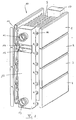
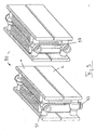
- Fig. 1 shows a convector radiator of a first embodiment according to the present invention in an exploded perspective view, while Fig. 2 illustrates this radiator in the assembled state.
- the radiator according to this first embodiment is provided overall with the reference numeral 10.
- the convector body 10 has on each of its flat sides four hollow plates 1, 2, 3 and 4, which transport a heating medium as flat heating tubes. Between Hollow plates are arranged convector blades 5, which form chimneys for the convective air passage.
- the convector body 10 has the distribution channel 12, while at the rear end side of the distribution channel 17 is mounted.
- the two distribution channels are connected via the connecting tube 16 with the hollow plates 1 to 4 in each case in the frontal region in connection.
- the attachment between the connecting tube 16 and the connection points on the hollow plates can be realized for example by resistance welding.
- the rectangular distribution channel 12 is divided by a horizontally extending web into two sections, namely a forward section 14 and a return section 15. This can be clearly seen in the cut-away area of FIG. 1.
- the distribution channel 17, however, is formed as a continuous rectangular tube.
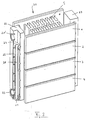
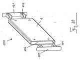
- FIG. 3 A particularly compact embodiment of a convector body 20 with a bottom-side supply connection is shown in FIG.
- Fig. 3 and in the further also for Figs. 4 to 9 is that the same reference numerals or reference numerals denote with identical last digits components corresponding to those in Figs. 1 and 2.
- the convector body 20 of Fig. 3, with the exception of the manifold 22 has the same structure as that of Figs. 1 and 2, and he also has the same flow guide except for this difference.
- the convector body 20 is a radiator with a bottom-side flow connection 21.
- This bottom-side flow connection 21 passes as a tube through the return section 25 of the distribution channel 22 and opens up in the flow section 24, from where the heating medium is then in turn passed to the top hollow plate 1.
- the flow pattern is the same as the convector body 10, i. the heating medium flows via the hollow plates 2, 3 and 4 back into the return section 25 and exits from the return port 23.
- With the implementation of the flow pipe 28 through the return section 25 space is saved in the interior of the radiator and it can, for. B. more slats 5 are arranged.
- the upper port 21 'in the flow section 24 can either be blind flanged or provided with a vent.
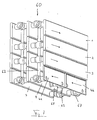
- FIG. 4 shows a front and a rear end perspective view of a convector body 30 according to a third embodiment.
- This convector body 30 has at the connection end face shown on the left a running only on the lower hollow plates 2, 3 and 4 rectangular distribution channel 32, which forms a total of only one return section.
- a rectangular distribution channel 37 extends over all hollow plates.
- the convector body 30 shown here is a radiator which has on the bottom side both the flow connection 38 and the return connection 33.
- the flow connection 38 leads as a pipe up to a commonly used fitting, which distributes the heating medium on both sides of the first hollow plate 1.
- two ports are provided on the distribution channel 37, of which the lower port 39 can be used as a further return port, while at the unspecified upper port, for example, a vent valve can be attached.
- valve in this case forms part of the convector body and is in particular clad accordingly.
- a similar convector radiator 40 is shown in FIG. 5.
- the difference to the Konvektörissonson 30 of FIG. 4 is that on the port side shown on the left side of the distribution channel 42 extends over all four hollow plates. Also, this distribution channel 42 is separated below the top hollow plate by a not visible here separation device. From the feed connection 48, a pipe leads behind the distribution channel 42 in its upper flow region, while the return connection 43 is provided at the bottom of the distribution channel 42. As can be seen from the diagram on the right, a return 49 as well as a ventilation connection at the top can also be provided here again on the opposite end side.
- the above embodiment may also be configured as a convector heater having a center port.
- FIG. 6 an alternative embodiment of a convector radiator according to the invention is now shown.
- This radiator has (on both sides) a divided lower hollow plate with a flow side 4a and a return side 4b.
- the two illustrations in Fig. 6 show the same radiator 50; the upper illustration is only slightly tilted to make the flow port 58 and the return port 59 visible.
- the flow guide is in this radiator the following (see also the arrows): Through the feed port 58, the heating medium enters the first half-shell half (lead half) 4a and is introduced from there via the distribution channel 52 in the upper hollow plates 1, 2 and 3, where it flows opposite to the direction indicated on the hollow plate half 4a.
- the distribution channel 52 is not divided, ie in this embodiment, the role of the separate lead section (see Fig. 1, reference numeral 14) is taken over by the hollow plate half 4a itself.
- the heating medium After flowing through the hollow plates 1, 2 and 3, the heating medium enters the rear manifold 57 and is directed from there down into the hollow plate half 4b, which forms a return half.
- the return port 59 is connected to the hollow plate half 4b and passes the heating medium back out of the radiator.
- FIG. 7 corresponds to the embodiment shown in FIG. 6 with regard to the basic flow guidance.
- the radiator 60 of FIG. 7, however, is a radiator with three heating plates, which are each formed of continuous hollow plates 1, 2 and 3.
- the lower hollow plate of the front heating plate is in turn divided into the flow and return halves 4a and 4b, so that the already discussed with reference to FIG. 6 flow is achieved.
- the radiator 60 instead of the rectangular distribution channels pipe distributor 62 and 67 with conventional fittings. Also, this radiator 60 has the bottom connections 68 (flow) and 69 (return).
- FIG. 8 again shows an embodiment of a heating element 80, which corresponds with respect to the flow guide to that shown in Fig. 1.
- This radiator 80 differs from the radiator 10 shown in FIG. 1 in that Instead of the rectangular distribution channels now pipe manifold 82 and 87 are used.
- the return section 82 has a downwardly outgoing return port 83 and extends to return the heating medium through the three lower hollow plates 2, 3 and 4.
- the rear manifold 87 all four hollow plates 1 to 4 connects with each other.
- the embodiment of the radiator 90 according to FIG. 9 corresponds in principle completely to that shown in FIG. 8, with the difference that the radiator shown here has only two superimposed hollow plates 1 and 2 on each side.
- the heating medium flows from the feed connection 91 through the hollow plate 1 and is passed via the return pipe manifold 97 through the hollow plate 2 back to the return port 93, which in turn goes down to the ground.
- the heating tube spacer assembly is designated by reference numeral 100. It consists of an already curved in shape hollow plate piece 1 and the spacers, which have a closure plate 101 and fork-like spacers 102.
- the end plates 101 are adapted or attached during manufacture to the end faces of the hollow plate 1, so that the fork-like spacers 102 penetrate into the cavity 103 and can serve as a spacer for the two lateral plates of the hollow plate 1. These spacers can neither slip nor block the flow through the hollow plate. 1
- FIG. 11 shows a further training possibility for the adjacent hollow plates.
- the hollow plates 1, 2 and 3 of the upper illustration and the two hollow plates 1 and 2 in the lower illustration were produced by rolling with the aid of profile rollers in the form of closed heating registers.
- the adjacent part A at a pitch of the hollow plate sections of about 70 mm has a width of about 10 mm.
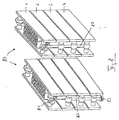
- Figures 12 and 13 illustrate a half shell construction of a convector body.
- the convector body is shown in perspective view in different sectional planes I, II and III.
- the representation I shows the convector body in half shell construction with the numbered from top to bottom flow channels 1 to 5 uncut.
- the front part of the convector body is cut away in the region of the connections, while the illustration III shows a convector body cut a little further back.
- heating plates which are composed of a front half-shell V and a rear half-shell H.
- the front half-shell V has the convexly curved flow channels 1 to 5, while in the rear half-shell H overflow channels U are provided which forward the heating medium at suitable locations from one flow channel to the other.
- overflow channels U are also designated in FIG. 12, it being apparent in section III that at the locations where the overflow channels U are present, the heating medium can pass from a flow channel into an adjacent flow channel.
- the desired flow guidance can be generated, in particular a flow guide, as previously described with reference to the previously illustrated embodiments.
Abstract
Description
Die vorliegende Erfindung betrifft einen Heiz- bzw. Kühlkörper der Gattung, wie sie durch den Oberbegriff des Patentanspruchs 1 bezeichnet wird. Insbesondere betrifft die Erfindung Konvektions-Heiz- bzw. -Kühlkörper, die im weiteren auch Konvektoren genannt werden.The present invention relates to a heating or cooling body of the type, as referred to by the preamble of
Solche Konvektoren, die meist eine oder mehrere parallel angeordnete Heizplatten aufweisen, welche wiederum aus im wesentlichen horizontal verlaufenden Hohlplatten (flache Heizrohre) ausgebildet sind, leiten das Heiz- bzw. Kühlmittel von einem Vorlaufanschluß über die Hohlplatten zu einem Rücklaufanschluß, wobei sich an der Heizplatte bzw. zwischen mehrere Heizplatten meist Konvektorlamellen befinden, die Konvektionskamine bilden, um die daran erwärmte bzw. abgekühlte Luft in einer bestimmten Richtung (meist nach oben oder nach unten) abzuleiten und dadurch einen kontinuierlichen Wärmetausch über den Luftstrom herzustellen.Such convectors, which usually have one or more parallel heating plates, which in turn are formed from substantially horizontally extending hollow plates (flat heating tubes), direct the heating or cooling agent from a flow connection via the hollow plates to a return connection, wherein on the heating plate or between several heating plates are usually convector blades that form convection chimneys to dissipate the heated or cooled air in a particular direction (usually up or down) and thereby produce a continuous heat exchange through the air flow.
Beispiele für Konvektor-Heizkörper sind in den deutschen Gebrauchsmustern DE 296 17 392 U1 und DE 297 05 694 U1 zu finden.Examples of convector radiators can be found in the German Utility Models DE 296 17 392 U1 and DE 297 05 694 U1.
Es ist die Aufgabe der vorliegenden Erfindung, einen gattungsgemäßen Heiz- bzw. Kühlkörper so auszugestalten, daß er eine hohe Funktionalität und eine zuverlässig optimierte Wärme- bzw. Kälteübertragung gestattet. Insbesondere sollen flexible Einbaumöglichkeiten geschaffen und eine optisch ansprechende Konstruktion ermöglicht werden.It is the object of the present invention to design a generic heating or cooling body so that it has a high functionality and a reliable optimized heat or cold transmission allowed. In particular, flexible installation options should be created and a visually appealing construction should be made possible.
Diese Aufgabe wird erfindungsgemäß durch die im kennzeichnenden Teil des Patentanspruchs 1 aufgeführten Merkmale gelöst. Die den Heiz- bzw. Kühlkörper betreffenden Unteransprüche beschreiben bevorzugte Ausführungsformen der Erfindung.This object is achieved by the features listed in the characterizing part of
Die erfindungsgemäße Ausgestaltung der Verteilung des Heiz- bzw. Kühlmediums im Konvektorkörper bietet vorteilhafterweise die Möglichkeit, die Vor- und Rücklaufanschlüsse je nach Belieben an verschiedene Stellen des Heiz- bzw. Kühlkörpers zu legen. Die Anordnung separater Verteilerkanäle, wie erfindungsgemäß vorgeschlagen wird, steigert noch die Flexibilität bei den Konstruktionsmöglichkeiten für einen Konvektorkörper. Eine besonders kompakte Anordnung ist dann zu erreichen, wenn der Vorlaufanschluß über ein durch den Rücklaufabschnitt eines ersten Verteilerkanals hindurch verlaufendes Rohr mit dem Vorlaufabschnitt eines separaten Verteilerkanals verbunden ist. Ein äußerlich ansprechendes Erscheinungsbild wird erfindungsgemäß dann zur Verfügung gestellt, wenn die vertikalen Stirnseiten des Konvektorkörpers im wesentlichen rechteckige, separate Verteilerkanäle aufweisen, die einen seitlichen Abschluß zur Verfügung stellen.The inventive design of the distribution of the heating or cooling medium in the convector body advantageously provides the opportunity to put the flow and return connections as desired at different points of the heating or cooling body. The arrangement of separate distribution channels, as proposed according to the invention, further increases the flexibility in the design possibilities for a convector body. A particularly compact arrangement can be achieved if the feed connection is connected via a through the return passage of a first distribution channel extending therethrough to the flow section of a separate distribution channel. An externally appealing appearance is provided according to the invention when the vertical end faces of the convector body have substantially rectangular, separate distribution channels which provide a lateral termination.
Die Vor- und Rücklaufanschlüsse eines erfindungsgemäßen Konvektorkörpers können erfindungsgemäß direkt oder über einen Abschnitt eines Verteilerkanals in eine obere, aber auch in eine untere geteilte Hohlplatte einmünden und dann weiter über die Verteileranordnung und die anderen Hohlplatten verbunden sein.The supply and return connections of a convector body according to the invention can according to the invention open directly or via a section of a distribution channel into an upper, but also into a lower divided hollow plate and then be connected further via the distributor arrangement and the other hollow plates.
Die Erfindung befaßt sich ferner mit einem Abstandshalter, der insbesondere zur Herstellung von Hohlplatten für einen Heiz- bzw. Kühlkörper verwendet wird. Bei der Herstellung der als Rechteckrohre ausgestalteten Hohlplatten müssen Abstandshalter zwischen die aneinander zu biegenden flachen Abschnitte der Hohlplatten eingesetzt werden, um zu verhindern, daß der Hohlraum bei der Verarbeitung eingedrückt wird. Hierzu werden im Stand der Technik runde Scheiben eingesetzt, die Durchströmöffnungen aufweisen. Derartige runde Scheiben sind aber dahingehend kritisch, daß sie möglicherweise während des Herstellungsprozesses verrutschen und so ihre Funktion als Abstandshalter nicht mehr aufrechterhalten können.The invention further relates to a spacer, which is used in particular for the production of hollow plates for a heating or cooling body. In the preparation of the hollow tubes configured as rectangular tubes spacers must be inserted between the flat portions of the hollow plates to be bent to each other be used to prevent the cavity is pressed during processing. For this purpose, round discs are used in the prior art, have the flow openings. However, such round discs are critical in that they may slip during the manufacturing process and thus can no longer maintain their function as spacers.
Die Erfindung löst das obige Problem durch die Bereitstellung eines Abstandshalters, der einen an der Stirnseite der Hohlplattenabschnitte ansetzbaren Ansetzteil und von diesem abragende Abstandsstücke aufweist, die in den Hohlraum der Hohlplatten hineinragen und insbesondere eine Höhe haben, die dem Innenabstand der Hohlplattenteile im wesentlichen entspricht.The invention solves the above problem by providing a spacer having an attachable part which can be attached to the front side of the hollow plate sections and spacers projecting therefrom, which project into the cavity of the hollow plates and in particular have a height substantially equal to the internal spacing of the hollow plate parts.
Weil die erfindungsgemäßen Abstandshalter mit ihrem Ansetzteil den stirnseitigen Abschluß der Hohlplatten bilden und damit unverrückbar angeordnet werden, werden auch die abragenden Abstandsstücke automatisch unverrückbar angeordnet, so daß bei der Fertigung keine Störungen wegen verschobener Abstandshalter mehr zu befürchten sind.Because the spacers according to the invention form with their Ansetzteil the frontal closure of the hollow plates and thus immovably arranged, the projecting spacers are automatically arranged immovable, so that in the production no disturbances due to shifted spacers are more to be feared.
Bei einer bevorzugten Ausführungsform der erfindungsgemäßen Abstandshalter ragen von einer als Ansetzteil ausgebildeten, im wesentlichen flachen, dem Stirnquerschnitt der Hohlplatte in der Form entsprechenden Platte mindestens ein, bevorzugt zwei gabelartig herausragende Abstandsstreifen ab.In a preferred embodiment of the spacers according to the invention, at least one, preferably two fork-like, protruding spacer strips protrude from a plate which is in the form of an attachment part and which is substantially flat and corresponds to the end cross-section of the hollow plate.
Die Erfindung wird im weiteren anhand verschiedener Ausführungsformen mittels der beiliegenden Zeichnungen näher erläutert. Es zeigen:
- Fig. 1 und 2
- einen erfindungsgemäßen Konvektor-Heizkörper gemäß einer ersten Ausführungsform in einer perspektiven Explosionsansicht und in einer perspektivischen Zusammenbau-Ansicht;
- Fig. 3
- eine perspektivische Explosionsansicht eines erfindungsgemäßen Heizkörpers gemäß einer zweiten Ausführungsform;
- Fig. 4
- zwei perspektivische Ansichten eines erfindungsgemäßen Heizkörpers gemäß einer dritten Ausführungsform der Erfindung von verschiedenen Stirnseiten her;
- Fig. 5
- zwei perspektivische Stirnansichten eines erfindungsgemäßen Heizkörpers gemäß einer vierten Ausführungsform der Erfindung;
- Fig. 6
- perspektivische Ansichten eines Heizkörpers gemäß einer fünften Ausführungsform der Erfindung mit einer unteren geteilten Hohlplatte und rechteckigen Verteilerkanälen;
- Fig. 7
- einen Konvektorkörper mit geteilter unterer Hohlplatte und einer RohrVerteileranordnung;
- Fig. 8
- einen Konvektorkörper mit Rohr-Verteileranordnung in perspektivischen Stirnansichten;
- Fig. 9
- einen Konvektorkörper mit wenigstens zwei Hohlplatten auf einer Heizplattenseite;
- Fig. 10
- eine erfindungsgemäße Abstandshalter-Konstruktion;
- Fig. 11
- durch Walzen hergestellte Hohlplattenanordnungen;
- Fig. 12
- einen Halbschalenaufbau eines Konvektorkörpers in verschiedenen Schnittansichten I, II, III; und
- Fig. 13
- eine aufgeklappte Darstellung des Halbschalen-Konvektors.
- Fig. 1 and 2
- a convector radiator according to a first embodiment of the invention in a perspective exploded view and in an assembly perspective view;
- Fig. 3
- an exploded perspective view of a radiator according to the invention according to a second embodiment;
- Fig. 4
- two perspective views of a radiator according to the invention according to a third embodiment of the invention from different end faces;
- Fig. 5
- two perspective end views of a radiator according to the invention according to a fourth embodiment of the invention;
- Fig. 6
- perspective views of a radiator according to a fifth embodiment of the invention with a lower split hollow plate and rectangular distribution channels;
- Fig. 7
- a convector body having a split lower cavity plate and a manifold assembly;
- Fig. 8
- a convector body with pipe manifold assembly in perspective end views;
- Fig. 9
- a convector body having at least two hollow plates on a Heizplattenseite;
- Fig. 10
- a spacer construction according to the invention;
- Fig. 11
- Hollow plate assemblies made by rolling;
- Fig. 12
- a half-shell construction of a convector body in different sectional views I, II, III; and
- Fig. 13
- an unfolded representation of the half-shell convector.
Die Fig. 1 zeigt einen Konvektor-Heizkörper einer ersten Ausführungsform nach der vorliegenden Erfindung in einer perspektivischen Explosionsansicht, während die Fig. 2 diesen Heizkörper in zusammengebautem Zustand darstellt. Der Heizkörper nach dieser ersten Ausführungsform ist insgesamt mit dem Bezugszeichen 10 versehen.Fig. 1 shows a convector radiator of a first embodiment according to the present invention in an exploded perspective view, while Fig. 2 illustrates this radiator in the assembled state. The radiator according to this first embodiment is provided overall with the
Der Konvektorkörper 10 weist auf jeder seiner flachen Seiten vier Hohlplatten 1, 2, 3 und 4 auf, die als flache Heizrohre ein Heizmedium transportieren. Zwischen den Hohlplatten sind Konvektorlamellen 5 angeordnet, die Kamine für den konvektiven Luftdurchzug bilden.The
An der vorderen Stirnseite weist der Konvektorkörper 10 den Verteilerkanal 12 auf, während an der hinteren Stirnseite der Verteilerkanal 17 angebracht ist. Die beiden Verteilerkanäle stehen über die Anschlußröhrchen 16 mit den Hohlplatten 1 bis 4 jeweils im stirnseitigen Bereich in Verbindung. Die Befestigung zwischen den Anschlußröhrchen 16 und den Anschlußstellen an den Hohlplatten kann beispielsweise durch Widerstandsverschweißung realisiert werden.At the front end side, the
Der rechteckig ausgebildete Verteilerkanal 12 ist durch einen horizontal verlaufenden Steg in zwei Abschnitte unterteilt, nämlich einen Vorlaufabschnitt 14 und einen Rücklaufabschnitt 15. Dies ist im freigeschnittenen Bereich der Fig. 1 deutlich zu sehen. Der Verteilerkanal 17 ist hingegen als durchgängiges Rechteckrohr ausgebildet.The
Im unteren Bereich des Verteilerkanals 12, nämlich im Rücklaufabschnitt 15, befindet sich der Rücklaufanschluß 13 des Konvektorkörpers, während der Vorlaufabschnitt 14 den Vorlaufanschluß 11 aufweist.In the lower region of the
Bei der Durchführung von Heizmedium durch den in den Fig. 1 und 2 dargestellten Konvektorkörper ergibt sich demnach folgender Strömungsablauf, der in Fig. 2 durch Pfeile an den Hohlplatten aufgezeichnet ist. Vom Vorlaufanschluß 11 aus erreicht das Heizmedium den Vorlaufabschnitt 14 und strömt über die Anschlußröhrchen 16 in die oberste erste Hohlplatte 1 (auf beiden Seiten des Konvektorkörpers) und von hier aus wiederum in den rechteckigen Verteilerkanal 17. Aus dem Verteilerkanal 17 wird das Heizmedium nunmehr in die Hohlplatten 2, 3 und 4 verteilt und strömt in entgegengesetzter Richtung zurück in den unteren Rücklaufabschnitt 15 des Verteilerkanals 12, wo es aus dem Rücklaufanschluß 13 austritt.When carrying out heating medium through the convector body shown in FIGS. 1 and 2, the following flow sequence results, which is recorded in FIG. 2 by arrows on the hollow plates. From the
Eine besonders kompakte Ausführungsform eines Konvektorkörpers 20 mit einem bodenseitigen Vorlaufanschluß ist in Fig. 3 dargestellt. Für die Fig. 3 und im weiteren auch für die Fig. 4 bis 9 gilt, daß gleiche Bezugszeichen bzw. Bezugszeichen mit identischen letzten Ziffern Bauteile bezeichnen, die denjenigen in Fig. 1 und 2 entsprechen.A particularly compact embodiment of a
Der Konvektorkörper 20 aus Fig. 3 weist mit Ausnahme des Verteilerrohrs 22 denselben Aufbau auf, wie derjenige aus den Fig. 1 und 2, und er hat ebenfalls bis auf diesen Unterschied dieselbe Strömungsführung. Der Konvektorkörper 20 ist ein Heizkörper mit einem bodenseitigen Vorlaufanschluß 21. Dieser bodenseitige Vorlaufanschluß 21 tritt als Rohr durch den Rücklaufabschnitt 25 des Verteilerkanals 22 hindurch und mündet oben in dem Vorlaufabschnitt 24, von wo aus das Heizmedium dann wiederum an die oberste Hohlplatte 1 weitergegeben wird. Der Strömungsverlauf ist im weiteren derselbe wie beim Konvektorkörper 10, d.h. das Heizmedium strömt über die Hohlplatten 2, 3 und 4 zurück in den Rücklaufabschnitt 25 und tritt aus dem Rücklaufanschluß 23 aus. Mit der Durchführung des Vorlaufrohres 28 durch den Rücklaufabschnitt 25 wird Platz im Inneren des Heizkörpers eingespart und es können z. B. mehr Lamellen 5 angeordnet werden. Der obere Anschluß 21' im Vorlaufabschnitt 24 kann entweder blind geflanscht oder mit einem Entlüfter versehen werden.The
Einen besonderen Vorteil bringt die erfindungsgemäß mögliche Zusammenfassung mehrerer Anschlußvarianten mit sich.A particular advantage brings the present invention possible summary of several connection variants with it.
Die Fig. 4 zeigt in einer vorderen und einer hinteren stirnseitigen perspektivischen Ansicht einen Konvektorkörper 30 gemäß einer dritten Ausführungsform. Dieser Konvektorkörper 30 weist an der links dargestellten Anschlußstirnseite einen lediglich über die unteren Hohlplatten 2, 3 und 4 verlaufenden rechteckigen Verteilerkanal 32 auf, der insgesamt lediglich einen Rücklaufabschnitt bildet. Auf der rechts dargestellten hinteren Entlüftungs-Stirnseite verläuft ein rechteckiger Verteilerkanal 37 über sämtliche Hohlplatten.FIG. 4 shows a front and a rear end perspective view of a
Der hier dargestellte Konvektorkörper 30 ist ein Heizkörper, der bodenseitig sowohl den Vorlaufanschluß 38 als auch den Rücklaufanschluß 33 aufweist. Der Vorlaufanschluß 38 führt als Rohr nach oben zu einem üblicherweise verwendeten Fitting, der das Heizmedium beidseitig auf die erste Hohlplatte 1 verteilt. Auch auf der rechts dargestellten Entlüftungs-Stirnseite sind am Verteilerkanal 37 zwei Anschlüsse vorgesehen, von denen der untere Anschluß 39 als weiterer Rücklaufanschluß verwendet werden kann, während an dem nicht bezeichneten oberen Anschluß beispielsweise ein Entlüftungsventil angebracht werden kann.The
Erfindungsgemäß kann auch ein Anschluß mit einem integrierten Ventil realisiert werden. Das Ventil bildet hierbei einen Teil des Konvektorkörpers und ist insbesondere entsprechend verkleidet.According to the invention, a connection with an integrated valve can be realized. The valve in this case forms part of the convector body and is in particular clad accordingly.
Einen ähnlichen Konvektor-Heizkörper 40 zeigt die Fig. 5. Der Unterschied zum Konvektörkörper 30 aus Fig. 4 besteht darin, daß auf der links dargestellten AnschlußStirnseite der Verteilerkanal 42 sich über alle vier Hohlplatten erstreckt. Auch dieser Verteilerkanal 42 ist unterhalb der obersten Hohlplatte durch eine hier nicht sichtbare Trenneinrichtung separiert. Vom Vorlaufanschluß 48 führt ein Rohr hinter dem Verteilerkanal 42 in dessen oberen Vorlaufbereich, während der Rücklaufanschluß 43 unten am Verteilerkanal 42 vorgesehen ist. Wie aus der rechten Darstellung hervorgeht, kann auch hier wieder auf der gegenüberliegenden Stirnseite sowohl unten ein Rücklauf49 als auch oben ein Entlüftungsanschluß vorgesehen werden.A
Die obige Ausführungsform kann auch als Konvektor-Heizkörper mit einem Mittenanschluß ausgestaltet werden.The above embodiment may also be configured as a convector heater having a center port.
In Fig. 6 ist nunmehr eine alternative Ausführungsform eines erfindungsgemäßen Konvektor-Heizkörpers gezeigt. Dieser Heizkörper weist (beidseitig) eine geteilte untere Hohlplatte mit einer Vorlaufseite 4a und einer Rücklaufseite 4b auf. Die beiden Darstellungen in Fig. 6 zeigen den gleichen Heizkörper 50; die obere Darstellung ist lediglich etwas abgekippt, um den Vorlaufanschluß 58 und den Rücklaufanschluß 59 sichtbar zu machen. Die Strömungsführung ist bei diesem Heizkörper die folgende (siehe auch die Pfeile): Durch den Vorlaufanschluß 58 gelangt das Heizmedium in die erste Hohlplattenhälfte (Vorlaufhälfte) 4a und wird von dort über den Verteilerkanal 52 in die oberen Hohlplatten 1, 2 und 3 eingeleitet, wo es entgegengesetzt der Richtung strömt, die an der Hohlplattenhälfte 4a angedeutet ist. Der Verteilerkanal 52 ist nicht geteilt, d.h. bei dieser Ausführungsform wird die Rolle des separaten Vorlaufabschnittes (siehe Fig. 1, Bezugszeichen 14) von der Hohlplattenhälfte 4a selbst übernommen. Nach dem Durchströmen der Hohlplatten 1, 2 und 3 tritt das Heizmedium in den hinteren Verteilerkanal 57 ein und wird von dort aus nach unten in die Hohlplattenhälfte 4b geleitet, die eine Rücklaufhälfte bildet. Der Rücklaufanschluß 59 ist mit der Hohlplattenhälfte 4b verbunden und leitet das Heizmedium wieder aus dem Heizkörper heraus.In Fig. 6, an alternative embodiment of a convector radiator according to the invention is now shown. This radiator has (on both sides) a divided lower hollow plate with a
Mit dieser Konstruktion ist es möglich, einen erfindungsgemäßen Konvektor mit einem Boden-Mittelanschluß zu versehen.With this construction, it is possible to provide a convector according to the invention with a bottom-middle connection.
Die Fig. 7 entspricht, was die grundsätzliche Strömungsführung betrifft, der in Fig. 6 dargestellten Ausführungsform. Der Heizkörper 60 nach Fig. 7 ist allerdings ein Heizkörper mit drei Heizplatten, die jeweils aus durchgängigen Hohlplatten 1, 2 und 3 gebildet werden. Die untere Hohlplatte der vorderen Heizplatte ist wiederum in die Vor- bzw. Rücklaufhälften 4a und 4b unterteilt, so daß die schon anhand der Fig. 6 erörterte Strömung erzielt wird. Im Unterschied zum Heizkörper 50 weist der Heizkörper 60 jedoch anstelle der rechteckigen Verteilerkanäle Rohrverteiler 62 und 67 mit üblichen Fittings auf. Auch dieser Heizkörper 60 weist die Bodenanschlüsse 68 (Vorlauf) und 69 (Rücklauf) auf.FIG. 7 corresponds to the embodiment shown in FIG. 6 with regard to the basic flow guidance. The
Die Fig. 8 zeigt wiederum eine Ausführungsform eines Heizkörpers 80, die bezüglich der Strömungsführung derjenigen entspricht, die in Fig. 1 dargestellt ist. Dieser Heizkörper 80 unterscheidet von dem in Fig. 1 dargestellten Heizkörper 10 dadurch, daß anstelle der rechteckigen Verteilerkanäle nunmehr Rohrverteiler 82 und 87 verwendet werden. Desweiteren weist der Rücklaufabschnitt 82 einen nach unten abgehenden Rücklaufanschluß 83 auf und erstreckt sich zur Rückführung des Heizmediums über die drei unteren Hohlplatten 2, 3 und 4. In der rechten Ansicht ist wiederum zu sehen, daß der rückwärtige Rohrverteiler 87 alle vier Hohlplatten 1 bis 4 miteinander verbindet.FIG. 8 again shows an embodiment of a
Die Ausführungsform des Heizkörpers 90 gemäß Fig. 9 entspricht im Prinzip vollständig derjenigen, die in Fig. 8 gezeigt wurde, mit dem Unterschied, daß der hier dargestellte Heizkörper lediglich zwei übereinander angeordnete Hohlplatten 1 und 2 auf jeder Seite aufweist. Das Heizmedium strömt vom Vorlaufanschluß 91 durch die Hohlplatte 1 und wird über den Rücklauf-Rohrverteiler 97 durch die Hohlplatte 2 zurück zum Rücklaufanschluß 93 geleitet, der wiederum nach unten zum Boden hin abgeht.The embodiment of the radiator 90 according to FIG. 9 corresponds in principle completely to that shown in FIG. 8, with the difference that the radiator shown here has only two superimposed
In Fig. 10 ist nunmehr das Prinzip erfindungsgemäßer Abstandshalter gezeigt. Die Heizrohr-Abstandshalteranordnung ist mit dem Bezugszeichen 100 versehen. Sie besteht aus einem schon in Form gebogenen Hohlplattenstück 1 sowie den Abstandshaltern, die eine Abschlußplatte 101 und gabelartige Abstandsstücke 102 aufweisen. Die Abschlußplatten 101 werden bei der Herstellung an die Stirnseiten der Hohlplatte 1 angepaßt bzw. angesetzt, so daß die gabelartigen Abstandsstücke 102 in den Hohlraum 103 eindringen und als Abstandshalter für die beiden seitlichen Platten der Hohlplatte 1 dienen können. Diese Abstandsstücke können weder verrutschen noch blockieren sie die Durchströmung der Hohlplatte 1.In Fig. 10, the principle of inventive spacer is now shown. The heating tube spacer assembly is designated by
In Fig. 11 zeigt eine weitere Ausbildungsmöglichkeit für die aneinanderliegenden Hohlplatten. Die Hohlplatten 1, 2 und 3 der oberen Darstellung und die beiden Hohlplatten 1 und 2 in der unteren Darstellung wurden durch Walzen mit Hilfe von Profilwalzen in Form von geschlossenen Heizregistern hergestellt. Bei der hier dargestellten Ausführungsform hat der aneinanderliegende Teil A bei einer Teilung der Hohlplattenabschnitte von etwa 70 mm eine Breite von ungefähr 10 mm.In Fig. 11 shows a further training possibility for the adjacent hollow plates. The
Die Figuren 12 und 13 veranschaulichen einen Halbschalenaufbau eines Konvektorkörpers. In Fig. 12 ist der Konvektorkörper in perspektivischer Ansicht in verschiedenen Schnittebenen I, II und III dargestellt. Die Darstellung I zeigt den Konvektorkörper in Halbschalenbauweise mit den von oben nach unten nummerierten Strömungskanälen 1 bis 5 ungeschnitten. In der Ansicht II ist der vordere Teil des Konvektorkörpers im Bereich der Anschlüße weggeschnitten, während die Darstellung III einen noch etwas weiter hinten geschnittenen Konvektorkörper zeigt.Figures 12 and 13 illustrate a half shell construction of a convector body. In Fig. 12, the convector body is shown in perspective view in different sectional planes I, II and III. The representation I shows the convector body in half shell construction with the numbered from top to
In Verbindung mit der in Fig. 13 dargestellten aufgeklappten Ansicht eines solchen Halbschalen-Konvektorkörpers wird nunmehr klar, daß dieser Heizplatten hat, die sich aus einer vorderen Halbschale V sowie einer hinteren Halbschale H zusammensetzen. Die vordere Halbschale V weist die konvex ausgebuchteten Strömungskanäle 1 bis 5 auf, während in der hintere Halbschale H Überlaufkanäle U vorgesehen sind, die das Heizmedium an geeigneten Stellen von einem Strömungskanal zum anderen weiterleiten. Diese Überlaufkanäle U sind auch in Fig. 12 bezeichnet, wobei im Schnitt III ersichtlich wird, daß an den Stellen, wo die Überlaufkanäle U vorhanden sind, das Heizmedium von einem Strömungskanal in einen benachbarten Strömungskanal übertreten kann.In connection with the unfolded view of such a half-shell convector body shown in Fig. 13, it is now clear that this has heating plates, which are composed of a front half-shell V and a rear half-shell H. The front half-shell V has the convexly
Durch eine geeignete Anordnung der Überlaufkanäle U kann die gewünschte Strömungsführung erzeugt werden, insbesondere eine Strömungsführung, wie sie vorher unter Bezugnahme auf die bisher dargestellten Ausführungsformen beschrieben wurde.By a suitable arrangement of the overflow channels U, the desired flow guidance can be generated, in particular a flow guide, as previously described with reference to the previously illustrated embodiments.
Claims (6)
- Heating or cooling body having hollow lines or plates extending substantially horizontally, a feed connection (11) and a return connection (13) and also a distributor arrangement for the heating or cooling medium,a) wherein the feed connection is connected to an inlet side of a first hollow line or plate (1, 4a) which directs the heating and cooling medium downstream by way of its outlet side into the distributor arrangement from which it is guided back by way of the rest of the hollow lines or plates to the return connection,b) wherein the distributor connection has substantially rectangular, separate distributor ducts (12, 17), one (12) of which is divided into feed and return sections (14, 15) that are separated from each other, with the feed section (14) being connected to the inlet region of the first hollow line or plate (1), andc) wherein the feed connection (48) is connected to the feed section by way of a pipe that extends next to the return section of the first distributor duct (42),
characterised in thatd) the distributor arrangement is formed as a cover closing the heating or cooling body substantially on the end face. - Heating or cooling body according to claim 1, characterised in that the first hollow plate (1) is an upper, in particular the uppermost hollow plate of a heating- or cooling-body side.
- Heating or cooling body according to one of the previous claims, characterised in that the hollow lines or plates are arranged lying opposite a double-sided heating or cooling body.
- Heating body according to one of the previous claims, characterised in that arranged on the hollow plates or between two opposite hollow plates there are convector lamellae (5) that preferably form convective flues.
- Heating or cooling body according to one of the preceding claims, characterised in that it comprises at least one spacer for producing hollow plates (1), with the at least one spacer having an attachment portion (101), which can be attached to the end face of the hollow-plate sections, and spacer pieces (102), which project from the attachment portion (101) and project into the hollow space (103) of the hollow plates and in particular are of a height that substantially corresponds to the nominal spacing of the hollow-plate portions.
- Heating or cooling body according to the preceding claim, characterised in that projecting from a plate (101) that pertains to the at least one spacer and is formed as an attachment portion, is substantially flat and corresponds in shape to the end cross section of the hollow plates there is at least one, preferably two spacer strips (102) projecting out in the manner of a fork.
Applications Claiming Priority (3)
| Application Number | Priority Date | Filing Date | Title |
|---|---|---|---|
| DE19832051 | 1998-07-16 | ||
| DE19832051A DE19832051C2 (en) | 1998-07-16 | 1998-07-16 | Heater or heat sink manifold assembly |
| EP99113520A EP0972998B1 (en) | 1998-07-16 | 1999-07-05 | Manifold assembly for heating or cooling radiators |
Related Parent Applications (1)
| Application Number | Title | Priority Date | Filing Date |
|---|---|---|---|
| EP99113520A Division EP0972998B1 (en) | 1998-07-16 | 1999-07-05 | Manifold assembly for heating or cooling radiators |
Publications (2)
| Publication Number | Publication Date |
|---|---|
| EP1553363A1 EP1553363A1 (en) | 2005-07-13 |
| EP1553363B1 true EP1553363B1 (en) | 2007-01-03 |
Family
ID=7874322
Family Applications (2)
| Application Number | Title | Priority Date | Filing Date |
|---|---|---|---|
| EP99113520A Expired - Lifetime EP0972998B1 (en) | 1998-07-16 | 1999-07-05 | Manifold assembly for heating or cooling radiators |
| EP05008269A Expired - Lifetime EP1553363B1 (en) | 1998-07-16 | 1999-07-05 | Manifold assembly for heating or cooling radiators |
Family Applications Before (1)
| Application Number | Title | Priority Date | Filing Date |
|---|---|---|---|
| EP99113520A Expired - Lifetime EP0972998B1 (en) | 1998-07-16 | 1999-07-05 | Manifold assembly for heating or cooling radiators |
Country Status (3)
| Country | Link |
|---|---|
| EP (2) | EP0972998B1 (en) |
| AT (2) | ATE350628T1 (en) |
| DE (3) | DE19832051C2 (en) |
Families Citing this family (4)
| Publication number | Priority date | Publication date | Assignee | Title |
|---|---|---|---|---|
| DE10113125A1 (en) * | 2001-03-17 | 2002-09-19 | Kermi Gmbh | Radiator with a central valve set |
| DE102006001618A1 (en) * | 2006-01-11 | 2007-07-12 | Arbonia Ag | Radiator, has heating wall formed from multiple flat pipes, where flat pipes exhibit right-angled flat front walls that are formed by folding and welding webs that stick-out from open front sides of flat pipes |
| DE102013218369A1 (en) * | 2013-09-13 | 2015-03-19 | Hans-Alfred Balg | Lowest-energy radiator |
| CZ32005U1 (en) * | 2018-03-12 | 2018-08-28 | Korado, A.S. | A universal radiator |
Family Cites Families (11)
| Publication number | Priority date | Publication date | Assignee | Title |
|---|---|---|---|---|
| CH341292A (en) * | 1955-08-17 | 1959-09-30 | Runtal Holding Co Sa | Process for the production of heating walls and heating wall produced by this process |
| CH436191A (en) * | 1965-08-03 | 1967-05-31 | Runtal Holding Co Sa | Method of manufacturing a heating or cooling radiator and radiator produced by this method |
| CH431872A (en) * | 1965-11-17 | 1967-03-15 | Zehnder Ag Geb | Central heating radiator |
| DE2315737A1 (en) * | 1973-03-27 | 1974-10-10 | Liedelt Kg D F | RADIATOR FOR SINGLE PIPE HEATING SYSTEMS |
| CH654100A5 (en) * | 1981-03-12 | 1986-01-31 | Runtal Holding Co Sa | RADIATOR. |
| CH683126A5 (en) * | 1991-06-25 | 1994-01-14 | Runtal Holding Co Sa | Heating tube esp. forming part of heating wall |
| DE9412801U1 (en) * | 1994-08-08 | 1994-10-06 | Koenig Christel | Radiator arrangement |
| FR2738907B1 (en) * | 1995-09-15 | 1997-12-05 | Finimetal Societe De Finissage | UNIVERSAL CONNECTION DEVICE FOR TUBULAR RADIATOR |
| DE19535280C2 (en) * | 1995-09-22 | 1999-08-26 | Koenig | Radiator arrangement |
| DE29705694U1 (en) * | 1996-04-09 | 1997-06-26 | Vogel & Noot Waermetechnik Ag | Convector, convector blank and convector kit |
| DE29617392U1 (en) * | 1996-10-07 | 1996-11-21 | Agotech Ag | Convector radiator with heat radiation protection |
-
1998
- 1998-07-16 DE DE19832051A patent/DE19832051C2/en not_active Expired - Fee Related
-
1999
- 1999-07-05 AT AT05008269T patent/ATE350628T1/en not_active IP Right Cessation
- 1999-07-05 EP EP99113520A patent/EP0972998B1/en not_active Expired - Lifetime
- 1999-07-05 AT AT99113520T patent/ATE303564T1/en not_active IP Right Cessation
- 1999-07-05 DE DE59912483T patent/DE59912483D1/en not_active Expired - Fee Related
- 1999-07-05 EP EP05008269A patent/EP1553363B1/en not_active Expired - Lifetime
- 1999-07-05 DE DE59914130T patent/DE59914130D1/en not_active Expired - Fee Related
Also Published As
| Publication number | Publication date |
|---|---|
| EP0972998A3 (en) | 2002-08-07 |
| DE19832051A1 (en) | 2000-01-20 |
| ATE350628T1 (en) | 2007-01-15 |
| ATE303564T1 (en) | 2005-09-15 |
| EP1553363A1 (en) | 2005-07-13 |
| DE59914130D1 (en) | 2007-02-15 |
| EP0972998B1 (en) | 2005-08-31 |
| DE19832051C2 (en) | 2002-06-13 |
| DE59912483D1 (en) | 2005-10-06 |
| EP0972998A2 (en) | 2000-01-19 |
Similar Documents
| Publication | Publication Date | Title |
|---|---|---|
| DE2441652C3 (en) | Finned tube heat exchanger | |
| EP1643202B1 (en) | Heat exchanger | |
| DE102005019578A1 (en) | Device for heating by fluid circulation | |
| DE4441503A1 (en) | Heat exchanger esp. for motor vehicles | |
| DE10248665A1 (en) | Heat exchanger in serpentine design | |
| DE60208307T2 (en) | Tube for plate heat exchanger | |
| DE102005059920B4 (en) | Heat exchanger, in particular evaporator | |
| EP1553363B1 (en) | Manifold assembly for heating or cooling radiators | |
| DE102005048838A1 (en) | Heat exchanger for e.g. vehicle, with grid including parallel tubes and three connection headers, has single collection chamber with two groups of tubes connected to it | |
| EP1593536B1 (en) | Method of and arrangement for separating fluid streams in a heating device | |
| EP1227290B1 (en) | Radiator assembly | |
| WO2008003291A1 (en) | Heating unit, particularly tube radiator | |
| DE19638714A1 (en) | Mat-type heat exchanger for cooling and/or heating | |
| EP0816772B1 (en) | Air outlet | |
| DE2440184A1 (en) | Steel plate component for central heating radiators - steel plate halves are bent up to two separate flanges to form additional heating faces | |
| DE3229757C2 (en) | Profile tube for heat exchangers, in particular for space heaters | |
| DE19535280C2 (en) | Radiator arrangement | |
| DE102017204492A1 (en) | Heat exchanger for a fused-salt electrolysis cell | |
| EP3499167B1 (en) | Device for tempering a room and method for its manufacturing | |
| DE102007035817B4 (en) | tubular radiator | |
| EP1102016B1 (en) | Radiator | |
| EP2253493B1 (en) | Device for heating the interior of a motor vehicle | |
| DE10113589A1 (en) | radiator | |
| DE102016002347A1 (en) | Air duct for a rail vehicle, with heating element | |
| DE102006004983A1 (en) | Heat exchanger, in particular an evaporator, for a motor vehicle's air conditioning system has flow paths each with a multi-duct tube for coolant and inlet/outlet pipes to supply/drain the coolant |
Legal Events
| Date | Code | Title | Description |
|---|---|---|---|
| PUAI | Public reference made under article 153(3) epc to a published international application that has entered the european phase |
Free format text: ORIGINAL CODE: 0009012 |
|
| AC | Divisional application: reference to earlier application |
Ref document number: 0972998 Country of ref document: EP Kind code of ref document: P |
|
| AK | Designated contracting states |
Kind code of ref document: A1 Designated state(s): AT CH DE LI |
|
| 17P | Request for examination filed |
Effective date: 20050601 |
|
| AKX | Designation fees paid |
Designated state(s): AT CH DE LI |
|
| GRAP | Despatch of communication of intention to grant a patent |
Free format text: ORIGINAL CODE: EPIDOSNIGR1 |
|
| GRAS | Grant fee paid |
Free format text: ORIGINAL CODE: EPIDOSNIGR3 |
|
| GRAA | (expected) grant |
Free format text: ORIGINAL CODE: 0009210 |
|
| AC | Divisional application: reference to earlier application |
Ref document number: 0972998 Country of ref document: EP Kind code of ref document: P |
|
| AK | Designated contracting states |
Kind code of ref document: B1 Designated state(s): AT CH DE LI |
|
| REF | Corresponds to: |
Ref document number: 59914130 Country of ref document: DE Date of ref document: 20070215 Kind code of ref document: P |
|
| REG | Reference to a national code |
Ref country code: CH Ref legal event code: NV Representative=s name: KEMENY AG PATENTANWALTBUERO |
|
| PLBI | Opposition filed |
Free format text: ORIGINAL CODE: 0009260 |
|
| PLAX | Notice of opposition and request to file observation + time limit sent |
Free format text: ORIGINAL CODE: EPIDOSNOBS2 |
|
| 26 | Opposition filed |
Opponent name: RETTIG ICC B.V. Effective date: 20070925 |
|
| PLBB | Reply of patent proprietor to notice(s) of opposition received |
Free format text: ORIGINAL CODE: EPIDOSNOBS3 |
|
| PLCK | Communication despatched that opposition was rejected |
Free format text: ORIGINAL CODE: EPIDOSNREJ1 |
|
| PGFP | Annual fee paid to national office [announced via postgrant information from national office to epo] |
Ref country code: DE Payment date: 20090609 Year of fee payment: 11 Ref country code: CH Payment date: 20090727 Year of fee payment: 11 Ref country code: AT Payment date: 20090723 Year of fee payment: 11 |
|
| PLBN | Opposition rejected |
Free format text: ORIGINAL CODE: 0009273 |
|
| STAA | Information on the status of an ep patent application or granted ep patent |
Free format text: STATUS: OPPOSITION REJECTED |
|
| 27O | Opposition rejected |
Effective date: 20090506 |
|
| REG | Reference to a national code |
Ref country code: CH Ref legal event code: PL |
|
| PG25 | Lapsed in a contracting state [announced via postgrant information from national office to epo] |
Ref country code: CH Free format text: LAPSE BECAUSE OF NON-PAYMENT OF DUE FEES Effective date: 20100731 Ref country code: DE Free format text: LAPSE BECAUSE OF NON-PAYMENT OF DUE FEES Effective date: 20110201 Ref country code: LI Free format text: LAPSE BECAUSE OF NON-PAYMENT OF DUE FEES Effective date: 20100731 |
|
| REG | Reference to a national code |
Ref country code: DE Ref legal event code: R119 Ref document number: 59914130 Country of ref document: DE Effective date: 20110201 |
|
| PG25 | Lapsed in a contracting state [announced via postgrant information from national office to epo] |
Ref country code: AT Free format text: LAPSE BECAUSE OF NON-PAYMENT OF DUE FEES Effective date: 20100705 |