EP2619022B1 - Élément mélangeur et module mélangeur de deux flux d'air se croisant dans un appareil de climatisation - Google Patents
Élément mélangeur et module mélangeur de deux flux d'air se croisant dans un appareil de climatisation Download PDFInfo
- Publication number
- EP2619022B1 EP2619022B1 EP11754369.4A EP11754369A EP2619022B1 EP 2619022 B1 EP2619022 B1 EP 2619022B1 EP 11754369 A EP11754369 A EP 11754369A EP 2619022 B1 EP2619022 B1 EP 2619022B1
- Authority
- EP
- European Patent Office
- Prior art keywords
- mixing
- wall
- main
- air flow
- auxiliary
- Prior art date
- Legal status (The legal status is an assumption and is not a legal conclusion. Google has not performed a legal analysis and makes no representation as to the accuracy of the status listed.)
- Not-in-force
Links
Images

Classifications
-
- B—PERFORMING OPERATIONS; TRANSPORTING
- B01—PHYSICAL OR CHEMICAL PROCESSES OR APPARATUS IN GENERAL
- B01F—MIXING, e.g. DISSOLVING, EMULSIFYING OR DISPERSING
- B01F25/00—Flow mixers; Mixers for falling materials, e.g. solid particles
- B01F25/40—Static mixers
- B01F25/42—Static mixers in which the mixing is affected by moving the components jointly in changing directions, e.g. in tubes provided with baffles or obstructions
- B01F25/421—Static mixers in which the mixing is affected by moving the components jointly in changing directions, e.g. in tubes provided with baffles or obstructions by moving the components in a convoluted or labyrinthine path
- B01F25/423—Static mixers in which the mixing is affected by moving the components jointly in changing directions, e.g. in tubes provided with baffles or obstructions by moving the components in a convoluted or labyrinthine path by means of elements placed in the receptacle for moving or guiding the components
-
- B—PERFORMING OPERATIONS; TRANSPORTING
- B60—VEHICLES IN GENERAL
- B60H—ARRANGEMENTS OF HEATING, COOLING, VENTILATING OR OTHER AIR-TREATING DEVICES SPECIALLY ADAPTED FOR PASSENGER OR GOODS SPACES OF VEHICLES
- B60H1/00—Heating, cooling or ventilating [HVAC] devices
- B60H1/00007—Combined heating, ventilating, or cooling devices
- B60H1/00021—Air flow details of HVAC devices
- B60H1/00035—Air flow details of HVAC devices for sending an air stream of uniform temperature into the passenger compartment
-
- B—PERFORMING OPERATIONS; TRANSPORTING
- B60—VEHICLES IN GENERAL
- B60H—ARRANGEMENTS OF HEATING, COOLING, VENTILATING OR OTHER AIR-TREATING DEVICES SPECIALLY ADAPTED FOR PASSENGER OR GOODS SPACES OF VEHICLES
- B60H1/00—Heating, cooling or ventilating [HVAC] devices
- B60H1/00007—Combined heating, ventilating, or cooling devices
- B60H1/00021—Air flow details of HVAC devices
- B60H2001/00078—Assembling, manufacturing or layout details
- B60H2001/00092—Assembling, manufacturing or layout details of air deflecting or air directing means inside the device
Definitions
- the present invention relates to an air conditioner for two intersecting in the air conditioner air streams, which can be used in a vehicle, such as in FR 2 889 486 A1 ,
- HVAC Heating, Ventilating, and Air Conditioning
- Engl. Heating, ventilation and air conditioning the temperature control / temperature stratification requirements increase.
- mixing space or installation space in the HVAC is needed, in which cold and warm air can mix.
- the temperature control / stratification is achieved in many known HVAC with the help of Lucasleit tone and / or cold and warm channels.
- the present invention is based on the finding that two air streams with different temperatures in a small space can mix optimally when a mixing module with H-shaped section profile or an H-mixing module is used.
- the mixing module comprises at least one mixing element for improving the air mixing in air conditioning units and is suitable for two air streams which do not flow parallel to one another.
- the mixing element is formed with two quasi-parallel walls connected at the center by a wall normal to both walls and parallel to the intersecting air flows. A contact surface between cold and warm air is increased by such mixing elements by a multiple, whereby the mixing is significantly accelerated, the mixing module can, for. B. be installed after the radiator in the air conditioner. At the same time, the mixing elements serve as channels to guide air undisturbed at a certain temperature.
- the mixing module according to the invention necessary for temperature control and stratification control parts and channels in the air conditioner can be avoided, so that it does not come to high pressure losses and reduced power or recoverable amount of air conditioning. It also requires less space in the vehicle for the air conditioning.
- the above-mentioned internals in the form of the mixing module have a positive effect on the acoustics, so that noise can be minimized. It eliminates the optimization of the above-mentioned guiding parts, which development costs can be saved, especially in the trial and the calculation. Thus, a complex control of the system without high development costs is possible. The development costs are drastically reduced.
- the temperature stretch of the air at the channel outlets into the vehicle cabin can be advantageously solved thanks to the mixing space. Thereby the comfort for the passenger is positively influenced because there is no temperature stretch at the channel outlets.
- Ventilation and air conditioning are understood, as used for example in a vehicle.
- HVAC Heating, Ventilating, and Air Conditioning
- air streams of different temperatures can be generated and performed.
- these are a first and a second airflow.
- the air streams can be guided in this way that they intersect at a point in the air conditioner.
- the mixing element is arranged.
- the mixing element comprises the main wall and the two auxiliary walls.
- a sectional profile through the main wall and the side walls of the mixing element may be substantially H-shaped.
- the inflow directions of the two air streams in operation of the mixing element span the main extension plane of the main wall.
- the inflow directions can be predetermined by correspondingly arranged and shaped inlet openings or guide channels for the air streams.
- a shape of the mixing element may be adapted to a geometry of the space in which the mixing element is provided for obstruction. In particular, this applies to the side edges of the main wall to which no auxiliary walls are attached, and for the entire dimensioning of the mixing element. Edges of the main wall and the auxiliary walls may have a straight, curved or a mixture of a straight and curved course, for example a stepped and / or curved course.
- the main wall of the mixing area can be flowed around on both sides of its main extension plane of the first and the second air flow.
- the main wall is thus arranged in the mixing area. Both of their main surfaces can be touched by the two air streams. This offers the advantage that the mixing of the first and the second air stream can be carried out more efficiently, since the mixing zone is available on both sides of the main wall.
- a side edge of the first auxiliary wall and a side edge of the second auxiliary wall may have a projection over the main extension plane of the main wall.
- the projection over the main extension plane of the main wall may have the same amount in the first and the second auxiliary wall.
- the supernatant can be viewed from both main surfaces of the main wall.
- the first and the second auxiliary wall each extend over at least a half length of the side edge of the main wall to which they are attached. At least half the length can mean here in particular approximately the entire length. This has the advantage that the mixing of the air streams over the entire height of the mixing area is supported by the turbulence caused by the secondary walls and thus becomes more efficient.
- a width of one of the auxiliary walls can amount to at most one fifth of a distance between the first and the second auxiliary wall. This condition can apply to both auxiliary walls.
- the width of one of the auxiliary walls is the distance between the two side edges of the auxiliary wall where the first airflow passes. This offers the advantage that with this dimensional ratio a very good mixing and turbulence of the air flows results.
- the main walls of the at least two mixing elements may be arranged opposite each other and spaced from each other, wherein the main extension planes of the main walls may have a common orientation.
- the main extension levels of the main walls of the at least two mixing elements can in this case substantially or approximately parallel to each other.
- the arrangement of one of the at least two mixing elements with respect to another of the at least two mixing elements may be described by a displacement of the one to the other mixing element in a direction which is approximately orthogonal to the main extension planes of their main walls. This offers the advantage that a further mixing of the two air streams is further optimized by this arrangement of the at least two mixing elements.
- a distance between opposite side edges of the secondary walls of adjacent mixing elements of the at least two mixing elements can amount to at most five times a width of an auxiliary wall.
- the mixing space can be the installation space in the air conditioning unit in which the mixing module can be installed.
- the shape of the mixing room can be predetermined by the structural conditions of the air conditioner.
- the first and the second inlet channel and the outlet channel are arranged on different sides of the mixing space. The side of the first inlet channel and the opposite side of the outlet channel can both adjoin the bottom side with the second inlet channel.
- the distance between opposite side edges of the auxiliary walls of the two mixing elements of the mixing module can be at most one third of a dimension of the mixing space in the direction of this distance. This offers the advantage that by this condition to the size ratio, the mixing of the two air streams can be optimized.
- Fig. 1 shows an isometric view of a mixing module with two mixing elements 100, according to an embodiment of the present invention.
- Each of the mixing elements 100 has a main wall 110, a first auxiliary wall 120 and a second auxiliary wall 130.
- the auxiliary walls 120, 130 are attached to the main wall 110.
- the two mixing elements 100 are identical in construction and shape, so that with regard to only one of the two mixing elements 100 is described in more detail.
- the main wall 110 of the mixing element 100 is a plate-shaped body.
- the main wall 110 thus has two main surfaces.
- a floor plan of the main wall 110 is of asymmetrical shape.
- an upper edge of the main wall 110 is shown with a stepped shape. More specifically, the upper edge of the main wall 110 has a stepped shape that includes a plurality of descending steps from the side of the first sub-wall 120 toward the side of the second sub-wall 130. Further, left and right side edges of the main wall 110 and a lower edge of the main wall 110 are shown in FIG Fig. 1 shown with a concavely curved course.
- the main wall 110 extends along a main extension plane between the first auxiliary wall 120 and the second auxiliary wall 130.
- the first auxiliary wall 120 is in Fig. 1 shown attached to the left side edge of the main wall 110.
- the outline of the first auxiliary wall 120 is rectangular, with a length of a long side of a multiple length of a Narrow side corresponds. In other words, the layout of the first auxiliary wall 120 corresponds to an elongated rectangle.
- the first auxiliary wall 120 is curved. The curvature follows the curvature of the side edge of the main wall 110 to which the first auxiliary wall 120 is attached.
- the first sub-wall 120 is attached to an adjacent side edge of the main wall 110 so that the entire side edge of the first sub-wall 120 is covered.
- the first auxiliary wall 120 is continuously curved along its longitudinal direction.
- a main extension plane of the first auxiliary wall 120 is at an angle to the main plane of extension of the main wall 110. More specifically, this is a right angle.
- a width of the first auxiliary wall 120 along a narrow side is dimensioned such that the first auxiliary wall 120 projects beyond both main surfaces of the main wall 110, In Fig. 1
- the amount by which the first sub-wall 120 projects beyond each of the two main surfaces of the main wall 110 is approximately four times the thickness of the main wall 110.
- the second auxiliary wall 130 has in Fig. 1 In approximately the same plan, the same alignment with respect to the main wall 110 and the same dimensions as the first auxiliary wall 120 on. Therefore, only differences of the second auxiliary wall 130 with respect to the first auxiliary wall 120 are captured at this point.
- the second auxiliary wall 130 differs from the first auxiliary wall 120 in FIG Fig. 1 however, in its curvature along its longitudinal direction.
- the curvature along the longitudinal direction of the second auxiliary wall 130 is adapted to the curvature of the side edge of the main wall 110 to which the second auxiliary wall 130 is attached.
- Fig. 1 is indicated that the second auxiliary wall 130 is not continuously curved or bent along its longitudinal direction.
- the curvature of the second auxiliary wall 130 is mainly in an upper portion thereof.
- a course of the second auxiliary wall 130 in a lower portion thereof is approximately straight.
- the second auxiliary wall 130 does not extend all the way from an upper end of the adjacent side edge of the main wall 110 to the lower one End of the side edge. There remains a portion of the side wall adjacent to the second side wall 130 exposed. A length of this exposed portion corresponds approximately to the width of one of the auxiliary walls 120, 130,
- the two mixing elements 100 having the mixing module are arranged relative to each other so that main surfaces of the main walls 110 of the mixing elements 100 are opposed to each other.
- the mixing elements 100 are spaced apart along a direction orthogonal to the main planes of extension of the main walls 110 of the mixing element 100. In Fig. 1 the distance between respective opposite side edges of the auxiliary walls 120, 130 is approximately a width of one of the auxiliary walls 120, 130.
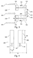
- Fig. 2 shows a side view of one of the mixing elements 100 of the mixing module Fig. 1 ,
- the main wall 110 is shown between the first auxiliary wall 120 and the second auxiliary wall 130.
- an air flow with a flow direction in the plane of Fig. 2 from a lower edge of the main wall 110 along a main extension direction of the main wall 110 to the upper edge of the main wall 110.
- the air flow 240 is an air flow with a temperature T u .
- the first auxiliary wall 120 is in Fig. 2 shown on the left and the second auxiliary wall 130 is shown on the right. From the main wall 110 is in Fig. 2 one of the main surfaces visible.
- the main wall 110 has four peripheral edges, representing an outline of the main wall 110.
- the upper edge of the main wall 110 has the step-shaped course, wherein the steps have different heights and lengths. In Fig. 2 For example, six such stages are shown.
- the lower edge of the main wall 110 has a slightly curved course.
- the lower edge of the main wall 110 forms an acute angle with the adjoining side edge.
- the side edges of the main wall 110 are at least partially curved.
- the left side edge of the main wall 110 is curved or bent substantially over its entire course.
- Fig. 1 The left side edge of the main wall 110 is curved or bent substantially over its entire course.
- the right-hand side edge of the main wall 110 has a curvature in its upper area, more precisely in its upper quarter, and has substantially no curvature in its remaining area.
- a length of the side edge shown on the left, to which the first auxiliary wall 120 is attached, is slightly smaller than a length of the side edge shown on the right, to which the second auxiliary wall 130 is attached.
- the first and the second auxiliary wall 120, 130 are bent or curved corresponding to the respectively adjacent side edges of the main wall 110 in the longitudinal profile.
- the longitudinal profile of the first auxiliary wall 120 follows the course of the adjacent, in Fig. 2 shown on the left, side edge of the main wall 110, Thus, the first auxiliary wall 120 is continuously curved in the longitudinal profile.
- the longitudinal profile of the second auxiliary wall 130 follows the course of the adjacent, in Fig. 2 Right side edge of the main wall 110.
- the second auxiliary wall 130 is curved in an upper portion and extends in a lower portion substantially straight.
- the second auxiliary wall 130 does not extend all the way from the upper end of the adjacent side edge of the main wall 110 to the lower end thereof.
- Fig. 3 shows a top view of the mixing module Fig. 1 , In the plan view in Fig. 3 In addition to the two mixing elements 100, an air flow 350 indicated by three arrows, a mixing region 360, a mixed air flow 370 indicated by three further arrows, a secondary wall width Rv and a distance T of the first auxiliary wall 120 to the second auxiliary wall 130 are shown. From the top view of Fig. 3 opens up an H-shaped floor plan of each mixing element 100 in profile, which is formed respectively by the first auxiliary wall 120, the main wall 110 and the second auxiliary wall 130.
- the airflow 350 which in Fig. 3 From the left edge of the drawing flows in the plane to the right, first meets the first side walls 120 of the two mixing elements 100. The air flow 350 then flows past the first side walls 120 at their side edges and enters the mixing region 360, the air flow 350 has a temperature T o .
- the mixing region 360 also enters the air flow 240 at the temperature T u .
- the airflow 240 is in Fig. 3 Although not shown, but would be in this representation in the mixing area 360 out of the drawing plane in the direction of a viewer of Fig. 3 stream.
- the air flow 240 mixes with the temperature T u and the air flow 350 with the temperature T o .
- the mixing region 360 viewed in the flow direction of the air flow 350, begins at those main surfaces of the first auxiliary walls 120 that face the respective second auxiliary walls 130.
- the mixing area 360 extends as far as the second side walls 130, more precisely up to those main surfaces of the second side walls 130 which face the first side walls 120 or also extend beyond the second side walls 130 to the right in FIG Fig. 3 ,
- the mixing area 360 extends into Fig. 3 also between the mixing elements 100, as well as above and below the same. The exact limits of the mixing area 360 also depend on the geometry of the room in which the mixing module is installed.
- the mixed air flow 370 which is mixed from the air flow 240 and the air flow 350, exits the mixing region 360 in the region of the second auxiliary walls 130 of the mixing elements 100.
- the mixed airflow 370 initially runs along the same direction as the airflow 350.
- the mixed airflow 370 may also change direction after leaving the mixing area 360. For example, the mixed airflow 370 may divide after exiting the mixing area 360 as shown in FIG Fig. 3 is shown.
- the auxiliary wall width Rv and the distance T of the first auxiliary wall 120 to the second auxiliary wall 130 are in Fig. 3 drawn by way of example for the lower mixing element 100, but of course also apply to the upper mixing element 100 in Fig. 3 ,
- the auxiliary wall width Rv corresponds to an extension of a narrow side edge of a first auxiliary wall 120 of a mixing element 100.
- the distance T of the first auxiliary wall 120 to the second auxiliary wall 130 is measured between those main surfaces of the first and second auxiliary wall 120, 130, which are facing away from each other.
- Rv / T ⁇ 0.2 generally applies for a good mixing result in the mixing region 360.
- the ratio is approximately 0.5 and the two mixing elements 100 have substantially the same dimensions and size relationships.
- Fig. 4 shows a front view of the mixing module Fig. 1 ,
- the view in Fig. 4 on the mixing elements 100 of the mixing module takes place along the flow direction of the air flow 350 in Fig. 3 ,
- the main surfaces of the first auxiliary walls 120 facing the air flow 350 as well as lower portions of the narrow sides of the main walls 110 are visible in the illustration.
- the two mixing elements 100 have substantially the same dimensions and proportions.
- In the front view of Fig. 4 On the two illustrated mixing elements 100 further dimensions and size ratios are illustrated.
- a distance Rh between opposite side edges of the first side walls 120 of the two mixing elements 100, a width B of an entire air duct in the space in which the mixing module is installed, and a height H of the first side walls 120 of the mixing elements are shown.
- the height H of the first auxiliary walls 120 of the mixing elements 100 may also correspond to the height of the second auxiliary walls 130.
- the height H corresponds to the extent of a long side edge of a first auxiliary wall 120.
- the width B is in Fig. 4 chosen arbitrarily, since the entire air-carrying channel is not shown.
- the distance Rh need not only apply to the opposite side edges of the first side walls 120, but may also apply to the opposite side edges of the second side walls 130, although the same in FIG Fig. 4 are not shown.
- the secondary wall width Rv drawn drawn.
- the following proportions in the mixing module apply.
- this ratio is approximately 4.
- the secondary wall width Rv is related to the distance Rh here generally according to Rv / Rh ⁇ 0.2. In Fig. 4 this ratio is approximately 1.
- the height H is approximately four times the auxiliary wall width Rv.
Landscapes
- Physics & Mathematics (AREA)
- Thermal Sciences (AREA)
- Engineering & Computer Science (AREA)
- Mechanical Engineering (AREA)
- Chemical & Material Sciences (AREA)
- Dispersion Chemistry (AREA)
- Chemical Kinetics & Catalysis (AREA)
Claims (8)
- Appareil de climatisation qui présente des caractéristiques suivantes :un espace de mélange pour deux flux d'air (240, 350) se croisant dans l'espace de mélange;un premier conduit d'entrée pour un premier flux d'air (350), conduit d'entrée qui est disposé en débouchant dans l'espace de mélange, au niveau d'un premier côté ;un deuxième conduit d'entrée pour un deuxième flux d'air (240), conduit d'entrée qui est disposé en débouchant dans l'espace de mélange, au niveau d'un côté du fond contigu au premier côté ;un conduit de sortie pour un flux d'air mélangé (370), conduit de sortie qui est disposé en sortant de l'espace de mélange, au niveau d'un deuxième côté placé à l'opposé du premier côté ; etil est prévu un module de mélange pour deux flux d'air (240, 350) se croisant dans un appareil de climatisation, où le module de mélange présente au moins deux éléments de mélange (100), où le module de mélange est disposé dans l'espace de mélange, où le premier et le deuxième flux d'air (240, 350) provenant des conduits d'entrée peuvent être mélangés dans le module de mélange, et le flux d'air mélangé (370) peut passer dans le conduit de sortie, où un élément de mélange (100) est conçu pour deux flux d'air se croisant dans un appareil de climatisation, où l'élément de mélange (100) présente des caractéristiques suivantes:une paroi principale (110) d'une zone de mélange (360) servant au mélange d'un premier flux d'air (350) et d'un deuxième flux d'air (240) se croisant avec le premier flux d'air (350), où la paroi principale (110) est disposée de manière telle, qu'au cours du fonctionnement de l'élément de mélange (100), une direction d'écoulement du premier flux d'air (350) entrant dans la zone de mélange (360) et une direction d'écoulement du deuxième flux d'air (240) entrant dans la zone de mélange (360) s'étendent longitudinalement par rapport à un plan principal d'étendue de la paroi principale (110) ; etune première et une deuxième paroi secondaire (120, 130) de la zone de mélange (360) qui sont fixées à chaque fois en ayant une surface principale sur des bords latéraux opposés de la paroi principale (110), où la première et la deuxième paroi secondaire (120, 130) sont disposées de manière telle, qu'au cours du fonctionnement de l'élément de mélange (100), la direction d'écoulement du premier flux d'air (350) entrant dans la zone de mélange (360) s'étende devant un bord latéral de la première paroi secondaire (120) et transversalement par rapport à la surface principale de la première paroi secondaire (120), que la direction d'écoulement du deuxième flux d'air (240) entrant dans la zone de mélange (360) s'étende longitudinalement par rapport à la surface principale de la première paroi secondaire (120), et de manière telle, qu'une direction d'écoulement d'un flux d'air mélangé (370) provenant du premier et du deuxième flux d'air (240, 350) et sortant de la zone de mélange (360) s'étende devant un bord latéral de la deuxième paroi secondaire (130) et transversalement par rapport à la surface principale de la deuxième paroi secondaire (130).
- Appareil de climatisation selon la revendication 1, dans lequel la paroi principale (110) de la zone de mélange (360) peut être baignée, des deux côtés du plan principal d'étendue de ladite paroi principale, par le premier et le deuxième flux d'air (240, 350).
- Appareil de climatisation selon l'une ou l'autre des revendications précédentes, dans lequel un bord latéral de la première paroi secondaire (120) et un bord latéral de la deuxième paroi secondaire (130) présentent une partie en porte-à-faux par rapport au plan principal d'étendue de la paroi principale (110).
- Appareil de climatisation selon l'une quelconque des revendications précédentes, dans lequel la première et la deuxième paroi secondaire (120, 130) s'étendent à chaque fois sur au moins une demi-longueur du bord latéral de la paroi principale (110), bord latéral sur lequel sont fixées lesdites parois secondaires.
- Appareil de climatisation selon l'une quelconque des revendications précédentes, dans lequel une largeur (Rv) de l'une des parois secondaires (120, 130) est égale au maximum à un cinquième d'une distance (T) comprise entre la première et la deuxième paroi secondaire (120, 130).
- Appareil de climatisation selon l'une quelconque des revendications 1 à 5, où les parois principales (110) des éléments de mélange (100) au moins au nombre de deux sont disposées en se faisant face l'une l'autre et en étant espacées l'une de l'autre, où les plans principaux d'étendue des parois principales (110) présentent une orientation commune.
- Appareil de climatisation selon la revendication 6, dans lequel une distance (Rh) comprise entre des bords latéraux opposés des parois secondaires (120, 130) d'éléments de mélange voisins (100) comptant au moins deux éléments de mélange (100) est égale au maximum au quintuple d'une largeur (Rv) d'une paroi secondaire (120, 130).
- Appareil de climatisation selon l'une quelconque des revendications 1 à 7, dans lequel la distance (Rh) comprise entre des bords latéraux opposés des parois secondaires (120, 130) des deux éléments de mélange (100) du module de mélange est égale au maximum à un tiers d'une dimension (B) de l'espace de mélange, suivant la direction de cette distance (Rh).
Applications Claiming Priority (2)
| Application Number | Priority Date | Filing Date | Title |
|---|---|---|---|
| DE102010041282A DE102010041282A1 (de) | 2010-09-23 | 2010-09-23 | Mischelement und Mischmodul für zwei sich in einem Klimagerät kreuzende Luftströme |
| PCT/EP2011/065349 WO2012038246A1 (fr) | 2010-09-23 | 2011-09-06 | Élément mélangeur et module mélangeur de deux flux d'air se croisant dans un appareil de climatisation |
Publications (2)
| Publication Number | Publication Date |
|---|---|
| EP2619022A1 EP2619022A1 (fr) | 2013-07-31 |
| EP2619022B1 true EP2619022B1 (fr) | 2016-04-06 |
Family
ID=44583035
Family Applications (1)
| Application Number | Title | Priority Date | Filing Date |
|---|---|---|---|
| EP11754369.4A Not-in-force EP2619022B1 (fr) | 2010-09-23 | 2011-09-06 | Élément mélangeur et module mélangeur de deux flux d'air se croisant dans un appareil de climatisation |
Country Status (5)
| Country | Link |
|---|---|
| US (1) | US9550155B2 (fr) |
| EP (1) | EP2619022B1 (fr) |
| CN (1) | CN103153658B (fr) |
| DE (1) | DE102010041282A1 (fr) |
| WO (1) | WO2012038246A1 (fr) |
Families Citing this family (2)
| Publication number | Priority date | Publication date | Assignee | Title |
|---|---|---|---|---|
| DE102012211669A1 (de) * | 2012-07-04 | 2014-01-09 | Behr Gmbh & Co. Kg | Klimaanlage |
| FR3050143A1 (fr) * | 2016-04-19 | 2017-10-20 | Valeo Systemes Thermiques | Composant en matiere plastique pour dispositif de chauffage, de ventilation ou d'air conditionne |
Family Cites Families (15)
| Publication number | Priority date | Publication date | Assignee | Title |
|---|---|---|---|---|
| US993242A (en) * | 1903-09-11 | 1911-05-23 | American Universal Mill Company | Solid-rolled cross-sectionally-h-shaped metal bar or structural section. |
| US1554108A (en) * | 1923-03-03 | 1925-09-15 | Jones & Laughlin Steel Corp | Metal beam |
| DE3817215C1 (en) * | 1988-05-17 | 1989-07-13 | Wolf Klimatechnik Gmbh, 8302 Mainburg, De | Mixing-air part for a mixing chamber of a ventilation or air-conditioning installation |
| FI91319C (fi) * | 1993-04-23 | 1994-06-10 | Flaekt Oy | Ilmastointilaitteiston tuloilman ja palautusilman välinen sekoitusosa |
| DE4416343C2 (de) * | 1994-05-09 | 1996-10-17 | Karlsruhe Forschzent | Statischer Mikro-Vermischer |
| US5520459A (en) * | 1994-06-30 | 1996-05-28 | The United States Of America As Represented By The Secretary Of The Navy | Enhancement of flow mixing by a frequency tunable cavity |
| FR2735723B1 (fr) | 1995-06-21 | 1997-08-01 | Valeo Climatisation | Dispositif de chauffage-ventilation de l'habitacle d'un vehicule automobile |
| DE19541266A1 (de) * | 1995-11-06 | 1997-05-07 | Bayer Ag | Verfahren und Vorrichtung zur Durchführung chemischer Reaktionen mittels eines Mikrostruktur-Lamellenmischers |
| DE19703779C2 (de) * | 1997-02-01 | 2003-06-05 | Karlsruhe Forschzent | Verfahren und Vorrichtung zur Herstellung eines dispersen Gemisches |
| JP4396014B2 (ja) | 2000-06-06 | 2010-01-13 | 株式会社デンソー | 空調装置 |
| JP4172013B2 (ja) * | 2003-02-10 | 2008-10-29 | 株式会社ヴァレオサーマルシステムズ | 自動車用空調装置 |
| JP4045215B2 (ja) * | 2003-07-14 | 2008-02-13 | 株式会社ケーヒン | 車両用空調装置 |
| JP2006137295A (ja) * | 2004-11-12 | 2006-06-01 | Mitsubishi Heavy Ind Ltd | 車両用空気調和機 |
| FR2889486B1 (fr) | 2005-08-03 | 2011-05-27 | Valeo Systemes Thermiques | Dispositif de repartition d'un flux d'air, pour une installation de chauffage, ventilation et/ou climatisation pour vehicule automobile et installation correspondante. |
| CN201348345Y (zh) | 2009-01-21 | 2009-11-18 | 奇瑞汽车股份有限公司 | 新型汽车空调多区域hvac装置 |
-
2010
- 2010-09-23 DE DE102010041282A patent/DE102010041282A1/de not_active Withdrawn
-
2011
- 2011-09-06 CN CN201180045769.XA patent/CN103153658B/zh not_active Expired - Fee Related
- 2011-09-06 WO PCT/EP2011/065349 patent/WO2012038246A1/fr active Application Filing
- 2011-09-06 EP EP11754369.4A patent/EP2619022B1/fr not_active Not-in-force
- 2011-09-06 US US13/825,645 patent/US9550155B2/en active Active
Also Published As
| Publication number | Publication date |
|---|---|
| CN103153658A (zh) | 2013-06-12 |
| DE102010041282A1 (de) | 2012-03-29 |
| CN103153658B (zh) | 2015-07-22 |
| US9550155B2 (en) | 2017-01-24 |
| US20130250718A1 (en) | 2013-09-26 |
| WO2012038246A1 (fr) | 2012-03-29 |
| EP2619022A1 (fr) | 2013-07-31 |
Similar Documents
| Publication | Publication Date | Title |
|---|---|---|
| DE102016216019A1 (de) | Einsatz für einen Kühlmantel einer elektrischen Maschine | |
| EP2508815B1 (fr) | Dispositif d'influence d'un flux d'air dans un composant d'une installation technique climatique | |
| DE102015119863A1 (de) | Elektrische Heizvorrichtung zum Heizen von Fluiden | |
| DE112019002399T5 (de) | Fluidabgabevorrichtung | |
| DE202021101741U1 (de) | Flachkanalanordnung für eine Downdraft-Dunstabzugshaube | |
| EP2423016B1 (fr) | Dispositif de mélange de deux flux d'air | |
| DE102011011710A1 (de) | Luftmischungs- und -verteilungsvorrichtung und Fahrzeugheizungs- oder -klimaanlage | |
| EP2619022B1 (fr) | Élément mélangeur et module mélangeur de deux flux d'air se croisant dans un appareil de climatisation | |
| DE3217803C2 (de) | Einbauteil für eine Mischkammer einer raumlufttechnischen Anlage | |
| EP2201639B1 (fr) | Module de batterie | |
| EP3285017A1 (fr) | Panneau de plafond radiant chauffant et rafraîchissant comprenant au moins un ventilateur | |
| DE102006008218B4 (de) | Kompakte Heizungs-, Lüftungs- und Klimatisierungs-Anlage in Flachbauweise für Kraftfahrzeuge | |
| EP0303850B1 (fr) | Dispositif de mélange d'air | |
| DE102005050881B3 (de) | Belüftungseinrichtung für einen Fahrzeuginnenraum | |
| EP0816772B1 (fr) | Sortie d'air | |
| EP2141429B1 (fr) | Tour de refroidissement hybride | |
| DE102006022088A1 (de) | Klimaanlage für ein Fahrzeug und Luftmischvorrichtung | |
| EP1561615B1 (fr) | Echangeur de chaleur | |
| EP1243870A2 (fr) | Radiateur | |
| DE102007043272B4 (de) | Einsatz für eine Sanitärarmatur | |
| DE202009011733U1 (de) | Vorrichtung zur Temperierung, insbesondere Luftkühlung einer Vielzahl von Gegenständen, insbesondere Einzelbatterien einer Stromversorgungseinheit für Kraftfahrzeuge | |
| DE102017127830B3 (de) | Fluidmischer mit versetzt angeordnetem Fluidkanalauslass, Brennkammer und Luftfahrzeug mit einem Fluidmischer | |
| WO2017153086A1 (fr) | Conduite de climatisation pour un véhicule ferroviaire, avec élément chauffant | |
| AT519365B1 (de) | Energiespeicher | |
| DE102022113854A1 (de) | Wärmeübertrager für ein Fahrzeug |
Legal Events
| Date | Code | Title | Description |
|---|---|---|---|
| PUAI | Public reference made under article 153(3) epc to a published international application that has entered the european phase |
Free format text: ORIGINAL CODE: 0009012 |
|
| 17P | Request for examination filed |
Effective date: 20130423 |
|
| AK | Designated contracting states |
Kind code of ref document: A1 Designated state(s): AL AT BE BG CH CY CZ DE DK EE ES FI FR GB GR HR HU IE IS IT LI LT LU LV MC MK MT NL NO PL PT RO RS SE SI SK SM TR |
|
| DAX | Request for extension of the european patent (deleted) | ||
| RAP1 | Party data changed (applicant data changed or rights of an application transferred) |
Owner name: MAHLE BEHR GMBH & CO. KG |
|
| GRAP | Despatch of communication of intention to grant a patent |
Free format text: ORIGINAL CODE: EPIDOSNIGR1 |
|
| INTG | Intention to grant announced |
Effective date: 20151005 |
|
| GRAS | Grant fee paid |
Free format text: ORIGINAL CODE: EPIDOSNIGR3 |
|
| GRAA | (expected) grant |
Free format text: ORIGINAL CODE: 0009210 |
|
| AK | Designated contracting states |
Kind code of ref document: B1 Designated state(s): AL AT BE BG CH CY CZ DE DK EE ES FI FR GB GR HR HU IE IS IT LI LT LU LV MC MK MT NL NO PL PT RO RS SE SI SK SM TR |
|
| REG | Reference to a national code |
Ref country code: GB Ref legal event code: FG4D Free format text: NOT ENGLISH |
|
| REG | Reference to a national code |
Ref country code: AT Ref legal event code: REF Ref document number: 787340 Country of ref document: AT Kind code of ref document: T Effective date: 20160415 Ref country code: CH Ref legal event code: EP |
|
| REG | Reference to a national code |
Ref country code: IE Ref legal event code: FG4D Free format text: LANGUAGE OF EP DOCUMENT: GERMAN |
|
| REG | Reference to a national code |
Ref country code: DE Ref legal event code: R096 Ref document number: 502011009358 Country of ref document: DE |
|
| REG | Reference to a national code |
Ref country code: LT Ref legal event code: MG4D Ref country code: NL Ref legal event code: MP Effective date: 20160406 |
|
| REG | Reference to a national code |
Ref country code: FR Ref legal event code: PLFP Year of fee payment: 6 |
|
| PG25 | Lapsed in a contracting state [announced via postgrant information from national office to epo] |
Ref country code: NL Free format text: LAPSE BECAUSE OF FAILURE TO SUBMIT A TRANSLATION OF THE DESCRIPTION OR TO PAY THE FEE WITHIN THE PRESCRIBED TIME-LIMIT Effective date: 20160406 |
|
| PG25 | Lapsed in a contracting state [announced via postgrant information from national office to epo] |
Ref country code: FI Free format text: LAPSE BECAUSE OF FAILURE TO SUBMIT A TRANSLATION OF THE DESCRIPTION OR TO PAY THE FEE WITHIN THE PRESCRIBED TIME-LIMIT Effective date: 20160406 Ref country code: IS Free format text: LAPSE BECAUSE OF FAILURE TO SUBMIT A TRANSLATION OF THE DESCRIPTION OR TO PAY THE FEE WITHIN THE PRESCRIBED TIME-LIMIT Effective date: 20160806 Ref country code: PL Free format text: LAPSE BECAUSE OF FAILURE TO SUBMIT A TRANSLATION OF THE DESCRIPTION OR TO PAY THE FEE WITHIN THE PRESCRIBED TIME-LIMIT Effective date: 20160406 Ref country code: LT Free format text: LAPSE BECAUSE OF FAILURE TO SUBMIT A TRANSLATION OF THE DESCRIPTION OR TO PAY THE FEE WITHIN THE PRESCRIBED TIME-LIMIT Effective date: 20160406 Ref country code: NO Free format text: LAPSE BECAUSE OF FAILURE TO SUBMIT A TRANSLATION OF THE DESCRIPTION OR TO PAY THE FEE WITHIN THE PRESCRIBED TIME-LIMIT Effective date: 20160706 |
|
| PG25 | Lapsed in a contracting state [announced via postgrant information from national office to epo] |
Ref country code: ES Free format text: LAPSE BECAUSE OF FAILURE TO SUBMIT A TRANSLATION OF THE DESCRIPTION OR TO PAY THE FEE WITHIN THE PRESCRIBED TIME-LIMIT Effective date: 20160406 Ref country code: RS Free format text: LAPSE BECAUSE OF FAILURE TO SUBMIT A TRANSLATION OF THE DESCRIPTION OR TO PAY THE FEE WITHIN THE PRESCRIBED TIME-LIMIT Effective date: 20160406 Ref country code: LV Free format text: LAPSE BECAUSE OF FAILURE TO SUBMIT A TRANSLATION OF THE DESCRIPTION OR TO PAY THE FEE WITHIN THE PRESCRIBED TIME-LIMIT Effective date: 20160406 Ref country code: SE Free format text: LAPSE BECAUSE OF FAILURE TO SUBMIT A TRANSLATION OF THE DESCRIPTION OR TO PAY THE FEE WITHIN THE PRESCRIBED TIME-LIMIT Effective date: 20160406 Ref country code: HR Free format text: LAPSE BECAUSE OF FAILURE TO SUBMIT A TRANSLATION OF THE DESCRIPTION OR TO PAY THE FEE WITHIN THE PRESCRIBED TIME-LIMIT Effective date: 20160406 Ref country code: GR Free format text: LAPSE BECAUSE OF FAILURE TO SUBMIT A TRANSLATION OF THE DESCRIPTION OR TO PAY THE FEE WITHIN THE PRESCRIBED TIME-LIMIT Effective date: 20160707 Ref country code: PT Free format text: LAPSE BECAUSE OF FAILURE TO SUBMIT A TRANSLATION OF THE DESCRIPTION OR TO PAY THE FEE WITHIN THE PRESCRIBED TIME-LIMIT Effective date: 20160808 |
|
| PG25 | Lapsed in a contracting state [announced via postgrant information from national office to epo] |
Ref country code: IT Free format text: LAPSE BECAUSE OF FAILURE TO SUBMIT A TRANSLATION OF THE DESCRIPTION OR TO PAY THE FEE WITHIN THE PRESCRIBED TIME-LIMIT Effective date: 20160406 |
|
| REG | Reference to a national code |
Ref country code: DE Ref legal event code: R097 Ref document number: 502011009358 Country of ref document: DE |
|
| PG25 | Lapsed in a contracting state [announced via postgrant information from national office to epo] |
Ref country code: RO Free format text: LAPSE BECAUSE OF FAILURE TO SUBMIT A TRANSLATION OF THE DESCRIPTION OR TO PAY THE FEE WITHIN THE PRESCRIBED TIME-LIMIT Effective date: 20160406 Ref country code: CZ Free format text: LAPSE BECAUSE OF FAILURE TO SUBMIT A TRANSLATION OF THE DESCRIPTION OR TO PAY THE FEE WITHIN THE PRESCRIBED TIME-LIMIT Effective date: 20160406 Ref country code: SK Free format text: LAPSE BECAUSE OF FAILURE TO SUBMIT A TRANSLATION OF THE DESCRIPTION OR TO PAY THE FEE WITHIN THE PRESCRIBED TIME-LIMIT Effective date: 20160406 Ref country code: DK Free format text: LAPSE BECAUSE OF FAILURE TO SUBMIT A TRANSLATION OF THE DESCRIPTION OR TO PAY THE FEE WITHIN THE PRESCRIBED TIME-LIMIT Effective date: 20160406 Ref country code: EE Free format text: LAPSE BECAUSE OF FAILURE TO SUBMIT A TRANSLATION OF THE DESCRIPTION OR TO PAY THE FEE WITHIN THE PRESCRIBED TIME-LIMIT Effective date: 20160406 |
|
| PLBE | No opposition filed within time limit |
Free format text: ORIGINAL CODE: 0009261 |
|
| STAA | Information on the status of an ep patent application or granted ep patent |
Free format text: STATUS: NO OPPOSITION FILED WITHIN TIME LIMIT |
|
| PG25 | Lapsed in a contracting state [announced via postgrant information from national office to epo] |
Ref country code: BE Free format text: LAPSE BECAUSE OF NON-PAYMENT OF DUE FEES Effective date: 20160930 Ref country code: SM Free format text: LAPSE BECAUSE OF FAILURE TO SUBMIT A TRANSLATION OF THE DESCRIPTION OR TO PAY THE FEE WITHIN THE PRESCRIBED TIME-LIMIT Effective date: 20160406 |
|
| 26N | No opposition filed |
Effective date: 20170110 |
|
| PG25 | Lapsed in a contracting state [announced via postgrant information from national office to epo] |
Ref country code: MC Free format text: LAPSE BECAUSE OF FAILURE TO SUBMIT A TRANSLATION OF THE DESCRIPTION OR TO PAY THE FEE WITHIN THE PRESCRIBED TIME-LIMIT Effective date: 20160406 |
|
| REG | Reference to a national code |
Ref country code: CH Ref legal event code: PL |
|
| GBPC | Gb: european patent ceased through non-payment of renewal fee |
Effective date: 20160906 |
|
| PG25 | Lapsed in a contracting state [announced via postgrant information from national office to epo] |
Ref country code: SI Free format text: LAPSE BECAUSE OF FAILURE TO SUBMIT A TRANSLATION OF THE DESCRIPTION OR TO PAY THE FEE WITHIN THE PRESCRIBED TIME-LIMIT Effective date: 20160406 |
|
| REG | Reference to a national code |
Ref country code: IE Ref legal event code: MM4A |
|
| PG25 | Lapsed in a contracting state [announced via postgrant information from national office to epo] |
Ref country code: IE Free format text: LAPSE BECAUSE OF NON-PAYMENT OF DUE FEES Effective date: 20160906 Ref country code: GB Free format text: LAPSE BECAUSE OF NON-PAYMENT OF DUE FEES Effective date: 20160906 Ref country code: CH Free format text: LAPSE BECAUSE OF NON-PAYMENT OF DUE FEES Effective date: 20160930 Ref country code: LI Free format text: LAPSE BECAUSE OF NON-PAYMENT OF DUE FEES Effective date: 20160930 |
|
| PG25 | Lapsed in a contracting state [announced via postgrant information from national office to epo] |
Ref country code: LU Free format text: LAPSE BECAUSE OF NON-PAYMENT OF DUE FEES Effective date: 20160906 |
|
| REG | Reference to a national code |
Ref country code: FR Ref legal event code: PLFP Year of fee payment: 7 |
|
| REG | Reference to a national code |
Ref country code: AT Ref legal event code: MM01 Ref document number: 787340 Country of ref document: AT Kind code of ref document: T Effective date: 20160906 |
|
| REG | Reference to a national code |
Ref country code: BE Ref legal event code: MM Effective date: 20160930 |
|
| PG25 | Lapsed in a contracting state [announced via postgrant information from national office to epo] |
Ref country code: AT Free format text: LAPSE BECAUSE OF NON-PAYMENT OF DUE FEES Effective date: 20160906 |
|
| PG25 | Lapsed in a contracting state [announced via postgrant information from national office to epo] |
Ref country code: CY Free format text: LAPSE BECAUSE OF FAILURE TO SUBMIT A TRANSLATION OF THE DESCRIPTION OR TO PAY THE FEE WITHIN THE PRESCRIBED TIME-LIMIT Effective date: 20160406 Ref country code: HU Free format text: LAPSE BECAUSE OF FAILURE TO SUBMIT A TRANSLATION OF THE DESCRIPTION OR TO PAY THE FEE WITHIN THE PRESCRIBED TIME-LIMIT; INVALID AB INITIO Effective date: 20110906 |
|
| PG25 | Lapsed in a contracting state [announced via postgrant information from national office to epo] |
Ref country code: MT Free format text: LAPSE BECAUSE OF FAILURE TO SUBMIT A TRANSLATION OF THE DESCRIPTION OR TO PAY THE FEE WITHIN THE PRESCRIBED TIME-LIMIT Effective date: 20160406 Ref country code: TR Free format text: LAPSE BECAUSE OF FAILURE TO SUBMIT A TRANSLATION OF THE DESCRIPTION OR TO PAY THE FEE WITHIN THE PRESCRIBED TIME-LIMIT Effective date: 20160406 Ref country code: MK Free format text: LAPSE BECAUSE OF FAILURE TO SUBMIT A TRANSLATION OF THE DESCRIPTION OR TO PAY THE FEE WITHIN THE PRESCRIBED TIME-LIMIT Effective date: 20160406 |
|
| PG25 | Lapsed in a contracting state [announced via postgrant information from national office to epo] |
Ref country code: BG Free format text: LAPSE BECAUSE OF FAILURE TO SUBMIT A TRANSLATION OF THE DESCRIPTION OR TO PAY THE FEE WITHIN THE PRESCRIBED TIME-LIMIT Effective date: 20160406 |
|
| REG | Reference to a national code |
Ref country code: FR Ref legal event code: PLFP Year of fee payment: 8 |
|
| PG25 | Lapsed in a contracting state [announced via postgrant information from national office to epo] |
Ref country code: AL Free format text: LAPSE BECAUSE OF FAILURE TO SUBMIT A TRANSLATION OF THE DESCRIPTION OR TO PAY THE FEE WITHIN THE PRESCRIBED TIME-LIMIT Effective date: 20160406 |
|
| PGFP | Annual fee paid to national office [announced via postgrant information from national office to epo] |
Ref country code: FR Payment date: 20200925 Year of fee payment: 10 |
|
| PGFP | Annual fee paid to national office [announced via postgrant information from national office to epo] |
Ref country code: DE Payment date: 20201118 Year of fee payment: 10 |
|
| REG | Reference to a national code |
Ref country code: DE Ref legal event code: R119 Ref document number: 502011009358 Country of ref document: DE |
|
| PG25 | Lapsed in a contracting state [announced via postgrant information from national office to epo] |
Ref country code: FR Free format text: LAPSE BECAUSE OF NON-PAYMENT OF DUE FEES Effective date: 20210930 Ref country code: DE Free format text: LAPSE BECAUSE OF NON-PAYMENT OF DUE FEES Effective date: 20220401 |