EP1227207A2 - Fensterbeschlag und Teile eines solchen Beschlages - Google Patents
Fensterbeschlag und Teile eines solchen Beschlages Download PDFInfo
- Publication number
- EP1227207A2 EP1227207A2 EP02075285A EP02075285A EP1227207A2 EP 1227207 A2 EP1227207 A2 EP 1227207A2 EP 02075285 A EP02075285 A EP 02075285A EP 02075285 A EP02075285 A EP 02075285A EP 1227207 A2 EP1227207 A2 EP 1227207A2
- Authority
- EP
- European Patent Office
- Prior art keywords
- carrier piece
- fitting
- extremity
- toothed
- laths
- Prior art date
- Legal status (The legal status is an assumption and is not a legal conclusion. Google has not performed a legal analysis and makes no representation as to the accuracy of the status listed.)
- Granted
Links
Images


Classifications
-
- E—FIXED CONSTRUCTIONS
- E05—LOCKS; KEYS; WINDOW OR DOOR FITTINGS; SAFES
- E05C—BOLTS OR FASTENING DEVICES FOR WINGS, SPECIALLY FOR DOORS OR WINDOWS
- E05C9/00—Arrangements of simultaneously actuated bolts or other securing devices at well-separated positions on the same wing
- E05C9/20—Coupling means for sliding bars, rods, or cables
-
- E—FIXED CONSTRUCTIONS
- E05—LOCKS; KEYS; WINDOW OR DOOR FITTINGS; SAFES
- E05C—BOLTS OR FASTENING DEVICES FOR WINGS, SPECIALLY FOR DOORS OR WINDOWS
- E05C9/00—Arrangements of simultaneously actuated bolts or other securing devices at well-separated positions on the same wing
- E05C9/06—Arrangements of simultaneously actuated bolts or other securing devices at well-separated positions on the same wing with three or more sliding bars
- E05C9/063—Arrangements of simultaneously actuated bolts or other securing devices at well-separated positions on the same wing with three or more sliding bars extending along three or more sides of the wing or frame
- E05C9/066—Locks for windows or doors specially adapted for tilt and turn
-
- E—FIXED CONSTRUCTIONS
- E05—LOCKS; KEYS; WINDOW OR DOOR FITTINGS; SAFES
- E05C—BOLTS OR FASTENING DEVICES FOR WINGS, SPECIALLY FOR DOORS OR WINDOWS
- E05C9/00—Arrangements of simultaneously actuated bolts or other securing devices at well-separated positions on the same wing
- E05C9/24—Means for transmitting movements between vertical and horizontal sliding bars, rods or cables for the fastening of wings, e.g. corner guides
Definitions
- This invention relates to a fitting for a window with a fixed frame and a wing, which fitting comprises at least one carrier piece which is shiftably attached to an edge of the wing, the fixed frame, respectively, in a fitting groove, and to laths which can be displaced by this carrier piece, which laths can be shifted in a fitting groove on said edge and possible on other edges of the wing or the fixed frame, of which at least a number are provided with at least one pin which cooperates with a closing part attached to the fixed frame, the wing, respectively.
- the locking and unlocking of such window is commanded by a handle attached to the wing or the fixed frame, which handle engages with a portion into the carrier piece in order to displace it.
- the windows have different dimensions, such that the lengths of the laths may differ from window to window.
- these laths are extruded profiled stiles of aluminium which are sawn to size by the window manufacturer, in function of the dimensions of the window and the position of the handle, and which subsequently are bored or punched in order to form openings which are necessary to couple them, by means of pins, to the carrier piece and possibly together or to other parts.
- the sawing to size of the laths and the boring or punching of the openings is very time-consuming for the manufacturer and requires relatively expensive machines, such that the manufactured laths are relatively expensive.
- a turn and tilt window comprises a wing which can hinge at one upright side of the fixed frame as well as tilt at the underside.
- the transition from tilting to turning or reverse is also commanded by the handle which is attached to the wing and engages into the carrier piece which is shiftably provided on an upright edge of the wing.
- This carrier piece is connected, by means of laths, to a tilting pin at the underside and, by means of laths and a corner connection, connected to a scissors mechanism which is mounted between the wing and the fixed frame.
- the laths must have a well-defined length, and the sawing of the laths then must be performed very precisely.
- the invention aims at providing a fitting, the laths of which no longer have to be sawn to size and punched by the manufacturer and which thus can be placed faster on a window, and whereby the laths are less expensive.
- this aim is achieved in that, in a first form of embodiment, the carrier piece, with each of its extremities, is coupled to a lath by means of mutually engaging toothed parts, to wit a toothed part at the extremity of the lath and a toothed part at the extremity of the carrier piece.
- the overall length of the laths along an edge can be pre-set.
- the laths also can be manufactured beforehand at the company's premises, with a number of standard sizes.
- the length of the toothed parts is at least 5 cm, and preferably at least 6 cm.
- the carrier piece preferably is provided with springy legs, with which it is snapped into the fitting groove.
- the laths first can be slid in the fitting groove into the desired position, after which the carrier piece is snapped onto this fitting groove, such that the toothed parts mutually engage.
- said aim is achieved in that a punching screw is screwed into each extremity of the carrier piece, and that the lath coupled to this extremity is slid with one end into the fitting groove underneath said extremity of the carrier piece and the punching screw is screwed into or through this extremity of the lath.
- the lath can be slid deeper or less deep under the carrier piece.
- the length of the laths along an edge can be adjusted, as a result of which the laths can be delivered beforehand by the manufacturer with a standard length. Beforehand, these laths need not have any openings for the coupling.
- This form of embodiment with a punching screw is recommended in the first place when a burglary delay is desired.
- the carrier piece preferably comprises a rib at one side and at the other side a groove which are slidably provided under, over, respectively, an edge of the fitting groove.
- the carrier piece In its side directed towards the bottom of the fitting groove, the carrier piece may comprise a recess for a flat extremity of a lath, which, for example, may comprise bevelled edges.
- the possible adjustment in the longitudinal direction of each coupling is, for example, 50 mm, such that in the longitudinal direction of the laths, a difference in length of 100 mm can be taken up.
- the laths coupled to the carrier piece also can be provided with a toothed part atltheir extremity distant from this latter, which toothed parts engages into a complementary toothed part of a part, for example, another lath, the movable part of a corner connection or the like.
- toothed parts do not have to be used for an adjustment in length, they may be shorter and have larger teeth then the aforementioned toothed parts.
- One of the mutually engaging toothed parts may be provided at the inner side of a hollowed thickened extremity, the other toothed part, for example, on a narrowed extremity.
- the fitting may comprise one or more laths which are provided with a toothed part on both extremities, whereby these toothed parts may be complementary or equal.
- the carrier pieces and the laths may be manufactured of synthetic material, for example, polyamide, preferably reinforced by fibers, such as glass fibers.
- the laths and other parts can be manufactured in a relatively inexpensive manner, for example, by injection moulding.
- the fitting may extend over more than one edge of the window, in which case it comprises at least one corner connection with a fixed part and a part which is movable therein, whereby an extremity of the movable part is connected to an extremity of the lath in the fitting groove by means of mutually engaging toothed parts.
- a corner connection which, with a part, is situated on the same edge as the carrier piece, can be coupled to a lath along an edge standing perpendicularly thereupon by means of similar toothed parts as those by which the carrier piece is coupled to a lath, according to said first form of embodiment.
- the fitting of a window can comprise a ramp-forming part which is provided at the fixed frame.
- this ramp-forming part is fixed on the window with a screw, which is time-consuming.
- the invention aims at enabling a faster mounting of the ramp-forming part.
- this aim is realized in that the ramp-forming part is snapped onto the fixed frame and, to this aim, comprises at least one springy leg which, with a small edge, engages under a small edge of a fitting groove on the fixed frame.
- This ramp-forming part may be manufactured of synthetic material, for example, polyamide, possibly reinforced by fibers, such as glass fibers.
- the fitting may comprise a locking part which is fixed on an upstanding edge of the fixed frame and which, with its lower extremity, sits in an opening which is provided in the ramp-forming part in order to prevent the shifting of this snapped-on ramp-forming part.
- the ramp-forming part also is provided with at least one opening for a shiftable hinge pin which is coupled to the carrier piece, preferably by the intermediary of laths which are coupled to this carrier piece and to each other in the above-described manner.
- a securing system is provided in order to prevent a shifting of this carrier piece when the window is tilted or turned open.
- This securing system comprises a lever which is fixed in a hinging manner on an extremity of the fixed portion of the corner connection.
- this lever is attached on the fixed portion by a rivet, as a result of which construction and mounting are relatively difficult.
- the invention also has as an aim to provide for such securing system which is simple in respect to construction and mounting.
- the fixed portion of the corner connection has at one extremity a head portion which, at the side directed towards the movable part, comprises an opening, whereas the lever, at the one side, has a pin which is provided in this opening and, at the other side, at a distance from the turning axis, has a locking pin which, for one position of the lever, becomes situated between locking pins on the movable part of the corner connection, when the wing is open, however, which is situated outside of the path of these locking pins when the wing is closed, and whereby the pin is surrounded by a spring which pushes the lever towards the above-mentioned position.
- the invention also relates to the parts, amongst others, the carrier piece, the laths and such, which are destined for forming part of a fitting according to any of the preceding forms of embodiment and which can be brought onto the market separately.
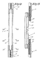
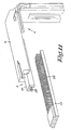
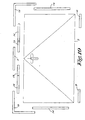
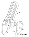
- the fitting for a turn and tilt window consisting of a fixed frame 1 and a wing 2, which schematically is represented in figure 1 (without the frame 1 and the wing 2), substantially comprises a number of parts, to wit, a carrier piece 3 which is shiftably attached to an upstanding edge of the wing 2, a corner connection 4 situated thereabove with a movable part 5 which is pliable and can be displaced in a fixed gutter-shaped part 6 which forms a corner of 90° and is fixed on the wing 2, a scissors mechanism 7 which is provided at the top of the window, between the frame 1 and the wing 2, more particularly a part of the upper hinge 8, and a hinge pin 9 which is provided below the carrier piece 3, at the bottom, on a lath 10 and which, in tilting position of the wing 2, penetrates into an opening 11 of a ramp-forming part 12 which is fixed on the lower horizontal part of the fixed frame 1.
- fitting grooves 15 which are provided on the profiles of the wing 2 and, as represented in the cross-sections of, amongst others, figures 4 to 6, are formed by two parallel ribs 16 which are bent towards each other with their outermost edges, such that grooves 16A are formed between these edges and the remainder of the profiled stile.
- These fitting grooves 15 extend over the entire length of the edges of the wing 2.
- the laths 13 are adjustment laths and the laths 14 are connection laths. They are of a different type, as will be described in the following, with different lengths in each type. Depending on the type, the ends are different, however, between the ends the laths are having the same cross-section, which is equal to a reversed T. At opposite sides, the head sits in the grooves 16A, wheras the stem of the T is situated between the edges of the ribs 16 directed towards each other.
- pins 17 are provided which can engage behind locking parts 17A which are attached to the fixed frame 1.
- the fitting also has laths 14 with pins 17 at said sides, a corner connection 18 next to the hinge pin 9, and a corner connection 19 next to the upper hinge 8.
- the lower hinge 8 is of a type known in itself, whereby a rotation around a vertical as well as around a horizontal axis is possible.
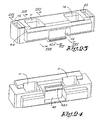
- the carrier piece 3 is a small elongated block which, with each of its extremities, is connected to a lath 13, in a manner which allows an adjustment in longitudinal direction, as long as the carrier piece 3 is not provided on the profiled stile of the wing 2.
- This carrier piece 3 has two recesses 20 in its center which give out to the side of the two laths 13 connected thereto and in the side wall of the carrier piece 3 standing thereupon and which serve for receiving the two legs of the fork of the handle, not represented in the figures, for operating the fitting.
- the two laths 13 have an extremity where the uppermost part, this is the part directed away from the bottom of the fitting groove 15, is cut away over approximately 7 centimeters and is replaced by a middlemost rib 21 which is provided with a toothed part 22 in the shape of corrugations distributed at regular interspaces, which extend over the exterior side and the longitudinal sides of the rib 21. On the last two centimeters, the lath 13 is narrowed in transverse direction, too.
- the toothed part 22 has a length larger than 5 cm, preferably larger than 6 cm, and which in the example is approximately seven centimeters.
- the carrier piece 3 Between the recesses 20 and up to a distance from each end, the carrier piece 3 at opposite sides has a springy leg 23, the edge of which shows a laterally protruding small edge which, when the carrier piece 3 is snapped into the fitting groove 15, engages under the bent edges of the two ribs 16, on the extremites on top of the lower part of an extremity of a lath 13.
- each extremity of the carrier piece 3 is provided with a recess 24, which fits over the rib 21 and which is provided with a toothed part 25 which is complementary to the toothed part 22 of a lath 13.
- the toothed part 25 also consists of corrugations which extend at regular mutual interspaces over the bottom and the side walls of the recess 24, and the overall length of the toothed part 25 is larger than 5 cm, preferably larger than 6 cm, and in the represented example is approximately seven centimeters.
- the toothed part 25 on each extremity engages into a toothed part 22 of a extremity of a lath 13 situated below, and this lath 13 is firmly connected to the carrier piece 3.
- the toothed parts 22 and 25 overlap each other to a major or minor extent, depending whether the lath 13, when snapping on the carrier piece 3, is situated further or less far underneath the carrier piece 3, such that an adjustment in longitudinal direction of approximately five centimeters at each extremity is possible.
- each lath 3 which is not provided with a toothed part 22, also is provided with a toothed part 26 which, however, is different and considerably shorter.
- this toothed part 26 is exclusively provided in longitudinal edges of the extremity which, in width direction, is narrower and, starting from the bottom of the fitting groove 15, is less high.
- This toothed part 26 cooperates with a complementary toothed part 27 on an extremity of a connection lath, this is a lath 14.
- This complementary toothed part 27 is provided at the inner side of a somewhat thickened extremity 28, which is hollow at its underside, in the two lateral edges 29 thereof.
- the toothed parts 26 and 27 are engaged into each other before both laths 13 and 14 are slid into the fitting groove 15. Once slid therein, the toothed parts 26 and 27 form a solid coupling of a lath 13 with a lath 14.
- the other extremity of the lath 14 comprises an extremity which has a shape similar to the extremity of the lath 13 with the toothed part 26 and which, thus, also comprises a toothed part 26.
- the lower end of the movable part 5 of the uppermost corner connection 4 has a rigid extremity along the upstanding edge of the wing 2, which extremity is similar to an extremity 28 and, thus, has a toothed part 27 in which, thus, in a manner analogous to the one described in the aforegoing, a toothed part 26 of a lath 14 engages.
- lath 13 and said movable part 5 instead of one, several laths 14 may be provided successively, as well as the lath 13 with its toothed part 26 may engage directly into the toothed part 27 of this part.
- the movable part 5 of the corner connection 4 comprises a second rigid extremity which is connected to said extremity by means of a band of spring steel and which is situated along the upper edge of the wing 2.
- This latter extremity consists of a gutter-shaped part 30 which is provided with a toothed part 25 at its interior side which is identical to the toothed part 25 in the carrier piece 3.
- the toothed part 25 at said extremity of the part 5 engages into the toothed part 22 at one extremity of a lath 13 which is situated in the fitting groove 15 on the upper edge of the wing 2.
- the length of the fitting can be adjusted in the longitudinal direction of said edge by approximately five centimeters.
- Said lath 13 engages with its toothed part 26 into the toothed part 27 of a lath 14, whereas the toothed part 26 of the last-mentioned lath 14 itself engages into a toothed part 27 which is provided on a second lath 14 or on an extremity of a lath 31 guided in the fitting groove 15 which extends underneath the scissors mechanism 7.
- This lath 31 is connected, by the intermediary of a lath 32, to an extremity of the movable part 5B of the corner connection 19.
- the lath 32 is provided with locking parts 33 for blocking the main lever 34 of the scissors mechanism 7 which is attached to a part of the uppermost hinge 8.
- the lath 32 has an extremity with a recess which engages on a block on the movable part 5B.
- this movable part 5B of the corner connection 19 is provided with a toothed part 27 at its extremity, with which toothed part it engages over a toothed part 26 of an additional lath 14 which extends along this upstanding edge, and thus is connected to the lath 14 by a coupling, such as represented in figure 9.
- Several additional laths 14 are connected to each other by such mutually engaging toothed parts 26 and 27 along said edge.
- the lath 13 coupled to this part at the bottom engages with its toothed part 26 into the toothed part 27 of a lath 14.
- the toothed part 26 of this lath 14 in its turn engages into a toothed part 27 on the upper end of said lath 10 which is provided with a recess at the bottom and carries the hinge pin 9.
- Said recess engages over a block which is provided on the movable part 5B of the corner connection 18 which is similar to the corner connection 19.
- toothed part 27 of this part 5B engages into the toothed part 26 of a lath 14 which can be shifted along the lower edge of the wing 2.
- the laths 13 and/or 14 can be made of aluminium as well as of synthetic material, for example, polyamide, which is reinforced by fibers, for example, glass fibers. Also, certain parts, such as the carrier piece 3, the fixed part of the corner connections 4, 18 and 19 can be manufactured of such synthetic material.
- a suitable synthetic material consists of 66 % polyamide en 30 % glass fibers.
- the carrier piece 3 is snapped into the vertical edge on the fitting groove 15, such that its toothed parts 25 engage with a number of teeth into the toothed part 22 of the two laths 13.
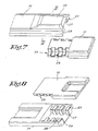
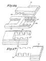
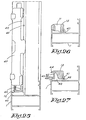
- This form of embodiment substantially differs from the form of embodiment described in the aforegoing, amongst others, in that the carrier piece 3 is realized heavier and no longer is coupled to the laths 13 by means of a toothed part, but by means of punching screws 35 and also is not snapped into the fitting groove 15, but slid therein.
- the carrier piece 3 also is a block having two recesses 20, however, the springy legs are replaced by an outwardly directed rib 36 at one side, which is interrupted by the recesses 20 and shiftably fits into the groove 16A and a groove 37 at the other side, into which fits the bent edge of a rib 16 situated at this side.
- a punching screw 35 is screwed into each extremity of the carrier piece 3, which, with its point, has punched a hole into a narrowed, but not provided with a toothed part, flat extremity 38 of a lath 13.
- the lateral edges of this extremity 38 are bevelled, and the carrier piece 3 is provided with a corresponding recess 39 at its underside, which underside is directed towards these extremities 38.
- the extremities 38 are relatively long, but the piece with a T-shaped cross-section of a lath 13 is extremely short, just sufficient for slidably retaining this lath 13 in a fitting groove 15.
- the laths 13 are only slid with their extremity 38 underneath the extremities of the carrier piece 3 after this latter, too, has been slid into the fitting groove 15.
- the punching screws 35 are screwed tight, such that they punch a hole through the extremities 38 in which they remain as connection pins. Therefore, the mounting and also the manufacturing of the carrier piece 3 is simple. It offers an excellent protection of the fork of the handle against deformation by a screwdriver of a burglar.
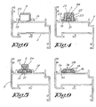
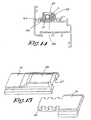
- toothed part 26 can be more narrow, whereas the toothed part 26 only has teeth on the lateral edges, such as represented in figure 15.
- the toothed part 27 cooperating with this toothed part 26 is unaltered in respect to the form of embodiment represented in figures 7 and 8.
- FIG. 16 Still another embodiment of a coupling between a toothed part 26 and a toothed part 27 is represented in figure 16.
- the toothed part 26 also only comprises teeth on the lateral edges.
- the hollowed extremity 28 with the toothed part 27 does not have to be thickened, as it was in the preceding forms of embodiment.
- toothed part 26 also only has teeth on the lateral edges, however, these are situated at a distance from the underside.
- the extremity 28 with the toothed part 27 also is not thickened and solely consists of the two lateral edges 29.
- laths 13 and 14 are described, it is obvious that other types are possible, too, such as laths having at both extremities an extremity 28 with a toothed part 27, for example, laths with a pin 17 thereupon, and laths having a toothed part 26 at both extremities. It is substantial that each time a toothed part 26 and a toothed part 27 can mutually engage in order to form a coupling.
- laths may be present which have a toothed part at only one extremity, for example, laths which are situated at the extremity of a connection or form part of one or the other mechanism.
- laths can not comprise any pins 17, whereas others, for exmaple, may comprise more than one pin 17.
- carrier pieces 3 and laths 13 and 14 described heretofore also can be applied with other windows than turn and tilt windows, whereby these parts can be mounted on the wing as well as on the fixed window. Parts, such as the scissors mechanism 7 or the hinge pin 9, are not present.
- corner connections 4 and/or 18 and/of 19 may be used.
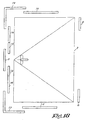
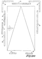
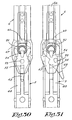
- FIG 21 also in an analogous manner, schematically a projecting window is represented.
- the wing 2 is attached at the fixed frame 1 at the top at opposite sides, by means of a scissors mechanism 7.
- a pivot-hung window is represented, whereby the wing 2 at opposite sides, at half of its height, is hinging around a horizontal axis in respect to the fixed frame 1.
- the fitting also may comprise ramp-forming parts 12, possibly without recesses 11 or with a recess 11 which is not used.
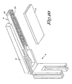
- this ramp-forming part 12 can be snapped into a fitting groove 40 on the edge of the fixed frame 1.
- This ramp-forming part 12 preferably is manufactured of synthetic material, for example, polyamide, possibly reinforced by fibers, such as glass fibers.
- this ramp-forming part 12 comprises an elongated block which, at one longitudinal side, is provided with a groove 41, whereas at the opposed side, it comprises a springy leg 42 having an outwardly directed edge 42A.
- the ramp-forming part 12 is slid with its groove 41 over the bent edge of one of the ribs 43 limiting the fitting groove 40, whereas the edge 42A of the leg 42, by springy deformation of this latter, is snapped under the bent edge of the other rib 43 and engages.
- the ramp-forming part 12 is provided with an ramp-like plane or bevel 44.
- this bevel cooperates with the fixed part 6 of the corner connection 18 in order to place the wing 2 in closed condition into the right position in respect to the fixed frame 1 in order to be able to realize a good closure.
- a complementary ramp-forming part can be snapped into the fitting groove 15 in a similar manner.
- the ramp-forming part 12 is provided against the upstanding edge of the fixed frame 1, and in order to prevent that it might shift in its longitudinal direction over the horizontal edge of the frame 1, it is retained at its place by a locking part 45 which is attached to the first-mentioned upstanding edge and with which cams standing on the lath 10 cooperate. With its lower extremity, the locking part 45 sits in an opening 46 at an extremity of the ramp-forming part 12, such as represented in detail in figure 23.
- the ramp-forming part 12 is symmetrical and has such an opening 46 in its upper side at each extremity.
- the ramp-forming part is provided with two recesses 11.
- the hinge pin 9 penetrates into one of these recesses 11 and hinges in this recess 11 during tilting.
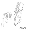
- a securing system is provided which prevents that, when the wing 2 is not closed, the system of laths 10, 13, 14, 31 and 32 is displaced by the carrier piece 3.
- the leg of the fixed part 6 which extends along the upstanding edge of the wing 2 comprises a protruding head part 47 which extends at the exterior side at a distance from the rigid extremity 48 of the movable part 4, which extremity is attached to a band 5A made of spring steel.
- This movable part 5 is represented in figures 30 and 31 only.
- a more or less triangular lever 49 is provided at the side of the extremity 48, at the head part 47 a more or less triangular lever 49 is provided in a pivotable manner.
- this lever 49 is provided with a pin 50 at one side which sits turnably in an opening 51 in the head part 47.
- the lever 49 is seated between the head part 47 and the rigid extremity 48 of the movable part 5.
- the pin 50 is surrounded by a countersunk spring 52, the legs of which extend at opposite sides of a part 49A of the lever 49 and are situated with their extremities at opposite sides of parts 47A of the head part 47, in such a manner that the spring 52 pushes the lever 49 always towards the position wherein the point of the lever 49 is directed downward.
- the lever 49 is represented in this position.
- the extremity 48 of the movable part 5 is provided with locking pins 54, 55 and 60 situated at a small distance from each other, which pins are directed towards the lever 49 and, for said position, represented in figure 30, of this lever 49, are situated above, below, respectively, the locking pin 53.
- the lever 49 Under the influence of the spring 52, the lever 49 automatically takes the aforementioned position when the wing 2 is turned or tilted open.
- the locking pin 53 is situated between the locking pins 54 and 55, the extremity 48 only can be shifted over a distance of approximately 3 mm.
- the spring 52 is put into the lever 49, after which the lever 49 with the spring 52 is placed against the head part 47, whereby the pin 50 penetrates into the opening 51. Finally, the movable part 5 is slid into the fixed part 6.
Priority Applications (3)
| Application Number | Priority Date | Filing Date | Title |
|---|---|---|---|
| EP04075952A EP1449998B1 (de) | 2001-01-29 | 2002-01-23 | Fensterbeschlag |
| EP04075954A EP1447509A3 (de) | 2001-01-29 | 2002-01-23 | Fensterbeschlag |
| EP04076011A EP1447505B1 (de) | 2001-01-29 | 2002-01-23 | Fensterbeschlag |
Applications Claiming Priority (2)
| Application Number | Priority Date | Filing Date | Title |
|---|---|---|---|
| BE200100068 | 2001-01-29 | ||
| BE2001/0068A BE1014943A3 (nl) | 2001-01-29 | 2001-01-29 | Beslag van een raam en onderdelen daarvoor. |
Related Child Applications (6)
| Application Number | Title | Priority Date | Filing Date |
|---|---|---|---|
| EP04076011A Division EP1447505B1 (de) | 2001-01-29 | 2002-01-23 | Fensterbeschlag |
| EP04075954A Division EP1447509A3 (de) | 2001-01-29 | 2002-01-23 | Fensterbeschlag |
| EP04075952A Division EP1449998B1 (de) | 2001-01-29 | 2002-01-23 | Fensterbeschlag |
| EP04075952.4 Division-Into | 2004-03-26 | ||
| EP04076011.8 Division-Into | 2004-03-26 | ||
| EP04075954.0 Division-Into | 2004-03-26 |
Publications (3)
| Publication Number | Publication Date |
|---|---|
| EP1227207A2 true EP1227207A2 (de) | 2002-07-31 |
| EP1227207A3 EP1227207A3 (de) | 2004-02-04 |
| EP1227207B1 EP1227207B1 (de) | 2013-07-03 |
Family
ID=3896839
Family Applications (4)
| Application Number | Title | Priority Date | Filing Date |
|---|---|---|---|
| EP04075954A Withdrawn EP1447509A3 (de) | 2001-01-29 | 2002-01-23 | Fensterbeschlag |
| EP02075285.3A Expired - Lifetime EP1227207B1 (de) | 2001-01-29 | 2002-01-23 | Fensterbeschlag und Teile eines solchen Beschlages |
| EP04076011A Expired - Lifetime EP1447505B1 (de) | 2001-01-29 | 2002-01-23 | Fensterbeschlag |
| EP04075952A Expired - Lifetime EP1449998B1 (de) | 2001-01-29 | 2002-01-23 | Fensterbeschlag |
Family Applications Before (1)
| Application Number | Title | Priority Date | Filing Date |
|---|---|---|---|
| EP04075954A Withdrawn EP1447509A3 (de) | 2001-01-29 | 2002-01-23 | Fensterbeschlag |
Family Applications After (2)
| Application Number | Title | Priority Date | Filing Date |
|---|---|---|---|
| EP04076011A Expired - Lifetime EP1447505B1 (de) | 2001-01-29 | 2002-01-23 | Fensterbeschlag |
| EP04075952A Expired - Lifetime EP1449998B1 (de) | 2001-01-29 | 2002-01-23 | Fensterbeschlag |
Country Status (8)
| Country | Link |
|---|---|
| US (1) | US6574927B2 (de) |
| EP (4) | EP1447509A3 (de) |
| AT (2) | ATE455224T1 (de) |
| BE (1) | BE1014943A3 (de) |
| DE (2) | DE60235113D1 (de) |
| DK (1) | DK1447505T3 (de) |
| ES (3) | ES2337356T3 (de) |
| PT (3) | PT1447505E (de) |
Cited By (7)
| Publication number | Priority date | Publication date | Assignee | Title |
|---|---|---|---|---|
| EP1491706A1 (de) * | 2003-06-27 | 2004-12-29 | SAVIO S.p.A. | Kraftübertragungsgestänge für Zubehörteile für Türe und Fenster |
| DE202004004009U1 (de) * | 2004-03-15 | 2005-07-28 | Mayer & Co. | Beschlaganordnung |
| EP1318258A3 (de) * | 2001-11-24 | 2006-02-08 | Roto Frank Ag | Beschlag an einem Flügel oder einem festen Rahmen eines Fensters, einer Tür oder dergleichen |
| EP1867821A1 (de) * | 2006-06-15 | 2007-12-19 | SAVIO S.p.A. | Treibstangenbeschlag eines Fensters oder einer Tür |
| RU2443842C1 (ru) * | 2008-03-20 | 2012-02-27 | Зигениа-Ауби Кг | Приводимый в действие рукояткой шпингалет с приводными штангами для окна или двери |
| CN103899168A (zh) * | 2014-04-15 | 2014-07-02 | 李健 | 一种门窗锁装置及一种铝合金门窗 |
| CN108571244A (zh) * | 2018-06-20 | 2018-09-25 | 佛山东鹏洁具股份有限公司 | 一种一键式快拆装柜门铰及其安装结构 |
Families Citing this family (8)
| Publication number | Priority date | Publication date | Assignee | Title |
|---|---|---|---|---|
| DE102004043973C5 (de) * | 2004-09-11 | 2008-10-09 | Roto Frank Ag | Verfahren zur Verbindung von Baugruppen einer Beschlaganordnung in einer Beschlagteilnut eines Tür- oder Fensterflügels |
| DE102004043942A1 (de) † | 2004-09-11 | 2006-03-30 | Roto Frank Ag | Beschlaganordnung für ein Fenster, eine Tür oder dergleichen |
| DE202010016354U1 (de) | 2010-12-08 | 2011-02-17 | Siegenia-Aubi Kg | Schließteil für einen Verriegelungsbeschlag |
| EP2735677B1 (de) * | 2012-11-21 | 2017-01-04 | Vita Corporation Co., Ltd. | Tür/Fenster mit einem Betriebssystem mit mehreren Verschlussstellen |
| DE102012112899A1 (de) * | 2012-12-21 | 2014-06-26 | Roto Frank Ag | Treibstangenbeschlag mit Fehlbedienungssperre und Fenster, Tür oder dergleichen mit einem derartigen Treibstangenbeschlag |
| US9404294B1 (en) * | 2014-01-21 | 2016-08-02 | Endura Products, Inc. | Astragal with adjustable length shoot bolt drive linkage |
| BE1023748B1 (nl) * | 2016-01-07 | 2017-07-11 | PARYS Emmanuel Diederich Camille VAN | Verdektliggend scharnier voor een draai-kip en kip-draai raam en raam daarmee uitgerust |
| BE1029013B1 (nl) * | 2021-01-14 | 2022-08-16 | Sobinco Fa | Verbindingslat voor raambeslag |
Citations (12)
| Publication number | Priority date | Publication date | Assignee | Title |
|---|---|---|---|---|
| GB1134461A (en) * | 1965-01-07 | 1968-11-27 | Heinz Schurmann & Co | A closure, e.g. a window or a door, for an aperture in a wall |
| DE7223874U (de) * | 1972-06-26 | 1972-10-05 | Ver Baubeschlagfab Gretsch & Coo Gmbh | Gestänge mit zwei miteinander verbundenen bzw. zu verbindenden Gestängegliedern |
| US4223928A (en) * | 1978-02-14 | 1980-09-23 | Siegenia-Frank Kg | Window hardware |
| FR2487419A1 (fr) * | 1980-07-25 | 1982-01-29 | Ferco Int Usine Ferrures | Ferrure de fenetre, porte ou analogue |
| DE3025885A1 (de) * | 1980-07-09 | 1982-02-04 | J. K. Koch, Koebenhavn | Beschlag von kipp-schwenk-fluegeln von fenstern, tueren o.dgl. |
| EP0492289A1 (de) * | 1990-12-28 | 1992-07-01 | FIAT AUTO S.p.A. | Einrichtung für das Justieren der Länge einer Stange, insbesondere eine Stange für die Operation eines Fahrzeugschlosses |
| EP0607007A1 (de) * | 1993-01-11 | 1994-07-20 | Schlegel (Uk) Holdings Limited | Fenstertreibstangenverschluss und Riegelkonstruktion |
| DE19511929C1 (de) * | 1995-03-31 | 1996-05-23 | Weidtmann Wilhelm Kg | Dreh- und/oder Kipp-Beschlag für Fenster, Türen od. dgl. mit einem zwischen dem Flügel und dem Rahmen angeordneten Flügelheber |
| DE19748059A1 (de) * | 1997-10-31 | 1999-05-06 | Weidtmann Wilhelm Kg | Treibstangenbeschlag für ein Fenster, eine Tür od. dgl. |
| EP1004737A1 (de) * | 1998-11-26 | 2000-05-31 | FERCO INTERNATIONAL Ferrures et Serrures de Bâtiment, Société Anonyme | Anhebevorrichtung für den Flügel einer Tür , eines Fensters oder dergleichen |
| EP1030015A1 (de) * | 1999-02-16 | 2000-08-23 | FERCO INTERNATIONAL Ferrures et Serrures de Bâtiment, Société Anonyme | Verriegelungsbeschlag des Typs mit Treibstangen oder ähnlichem |
| DE19913306A1 (de) * | 1999-03-24 | 2000-09-28 | Winkhaus Fa August | Beschlagsystem |
Family Cites Families (22)
| Publication number | Priority date | Publication date | Assignee | Title |
|---|---|---|---|---|
| NL7104154A (de) * | 1970-04-02 | 1971-10-05 | ||
| DE2026180A1 (de) * | 1970-05-29 | 1971-12-09 | Fa. Gustav Winterhoff, 5750 Menden | Dreh-Kipp-Beschlag, insbesondere Kipplager für Fenster, Türen o. dgl |
| DE2026368A1 (de) * | 1970-05-29 | 1971-12-09 | Fa. Wilhelm Weidtmann, 5620 Velbert | Sicherung gegen Fehlschaltungen für Dreh-Kipp-Flügel von Fenstern, Türen od. dgl |
| DE2166814A1 (de) * | 1971-04-14 | 1976-03-11 | Winkhaus Fa August | Beschlag fuer schwenk- oder kippbare fluegel von fenstern und tueren oder dergleichen |
| DE2142085B2 (de) * | 1971-08-21 | 1974-08-15 | Wilhelm Suhr, Baubeschlagfabrik Kg, 3051 Hagenburg | Kupplungsvorrichtung für Getriebegestänge an Fenstern oder Türen |
| DE2456057C2 (de) * | 1974-11-27 | 1983-09-08 | Wilh. Frank Gmbh, 7022 Leinfelden-Echterdingen | Kippriegellager für ein Fenster, eine Tür o.dgl. |
| AT331145B (de) * | 1974-11-28 | 1976-08-10 | Mayer & Co Riegel Beschlag | Gestange fur verschlusse von fenstern oder turen |
| DE2805465C2 (de) * | 1978-02-09 | 1984-11-15 | Fa. Aug. Winkhaus, 4404 Telgte | Treibstangenbeschlag |
| DE2826139A1 (de) * | 1978-06-15 | 1979-12-20 | Ver Baubeschlag Gretsch Co | Vorrichtung zur sicherung gegen fehlbedienung |
| GB8417165D0 (en) * | 1984-07-05 | 1984-08-08 | Wood T J | Securing system |
| DE9102450U1 (de) * | 1991-03-01 | 1992-06-25 | Ramsauer, Dieter, 5620 Velbert, De | |
| DE9203338U1 (de) * | 1992-03-12 | 1993-07-08 | Siegenia-Frank Kg, 5900 Siegen, De | |
| DE9212670U1 (de) * | 1992-09-21 | 1992-12-17 | Laeken Fensterzubehoer Gmbh, 4504 Georgsmarienhuette, De | |
| US5483779A (en) * | 1993-07-08 | 1996-01-16 | Exposystems, Inc. | Header frame for a display system |
| US5444958A (en) * | 1993-11-02 | 1995-08-29 | Lu; Ching-Nan | Door frame |
| DE9402511U1 (de) * | 1994-02-16 | 1994-04-07 | Roto Frank Ag | Beschlag für Fenster oder Türen o.dgl. |
| DE9404966U1 (de) * | 1994-03-23 | 1994-05-19 | Roto Frank Ag | Beschlag für Fenster, Türen o. dgl. |
| EP0694666B1 (de) * | 1994-07-26 | 1999-04-07 | Siegenia-Frank Kg | Fenster oder Tür mit Schliessstücken |
| FR2747433B1 (fr) * | 1996-04-10 | 1998-05-22 | Ferco Int Usine Ferrures | Element de ferrure pour porte, fenetre ou analogue, notamment une gache, destine a etre monte sur un profile en aluminium ou en pvc |
| DE19828034A1 (de) * | 1998-06-24 | 1999-12-30 | Winkhaus Fa August | Schließblech |
| FR2793511B1 (fr) * | 1999-05-11 | 2001-06-22 | Ferco Int Usine Ferrures | Element de ferrure de type gache |
| DE20000246U1 (de) * | 2000-01-12 | 2000-03-30 | Aubi Baubeschlaege Gmbh | Fehlbedienungssicherung |
-
2001
- 2001-01-29 BE BE2001/0068A patent/BE1014943A3/nl not_active IP Right Cessation
-
2002
- 2002-01-23 DE DE60235113T patent/DE60235113D1/de not_active Expired - Lifetime
- 2002-01-23 PT PT04076011T patent/PT1447505E/pt unknown
- 2002-01-23 PT PT04075952T patent/PT1449998E/pt unknown
- 2002-01-23 EP EP04075954A patent/EP1447509A3/de not_active Withdrawn
- 2002-01-23 AT AT04075952T patent/ATE455224T1/de active
- 2002-01-23 DE DE60231535T patent/DE60231535D1/de not_active Expired - Lifetime
- 2002-01-23 PT PT2075285T patent/PT1227207E/pt unknown
- 2002-01-23 ES ES04075952T patent/ES2337356T3/es not_active Expired - Lifetime
- 2002-01-23 ES ES04076011T patent/ES2320884T3/es not_active Expired - Lifetime
- 2002-01-23 ES ES02075285T patent/ES2428352T3/es not_active Expired - Lifetime
- 2002-01-23 EP EP02075285.3A patent/EP1227207B1/de not_active Expired - Lifetime
- 2002-01-23 DK DK04076011T patent/DK1447505T3/da active
- 2002-01-23 AT AT04076011T patent/ATE425334T1/de active
- 2002-01-23 EP EP04076011A patent/EP1447505B1/de not_active Expired - Lifetime
- 2002-01-23 EP EP04075952A patent/EP1449998B1/de not_active Expired - Lifetime
- 2002-01-29 US US10/058,018 patent/US6574927B2/en not_active Expired - Lifetime
Patent Citations (12)
| Publication number | Priority date | Publication date | Assignee | Title |
|---|---|---|---|---|
| GB1134461A (en) * | 1965-01-07 | 1968-11-27 | Heinz Schurmann & Co | A closure, e.g. a window or a door, for an aperture in a wall |
| DE7223874U (de) * | 1972-06-26 | 1972-10-05 | Ver Baubeschlagfab Gretsch & Coo Gmbh | Gestänge mit zwei miteinander verbundenen bzw. zu verbindenden Gestängegliedern |
| US4223928A (en) * | 1978-02-14 | 1980-09-23 | Siegenia-Frank Kg | Window hardware |
| DE3025885A1 (de) * | 1980-07-09 | 1982-02-04 | J. K. Koch, Koebenhavn | Beschlag von kipp-schwenk-fluegeln von fenstern, tueren o.dgl. |
| FR2487419A1 (fr) * | 1980-07-25 | 1982-01-29 | Ferco Int Usine Ferrures | Ferrure de fenetre, porte ou analogue |
| EP0492289A1 (de) * | 1990-12-28 | 1992-07-01 | FIAT AUTO S.p.A. | Einrichtung für das Justieren der Länge einer Stange, insbesondere eine Stange für die Operation eines Fahrzeugschlosses |
| EP0607007A1 (de) * | 1993-01-11 | 1994-07-20 | Schlegel (Uk) Holdings Limited | Fenstertreibstangenverschluss und Riegelkonstruktion |
| DE19511929C1 (de) * | 1995-03-31 | 1996-05-23 | Weidtmann Wilhelm Kg | Dreh- und/oder Kipp-Beschlag für Fenster, Türen od. dgl. mit einem zwischen dem Flügel und dem Rahmen angeordneten Flügelheber |
| DE19748059A1 (de) * | 1997-10-31 | 1999-05-06 | Weidtmann Wilhelm Kg | Treibstangenbeschlag für ein Fenster, eine Tür od. dgl. |
| EP1004737A1 (de) * | 1998-11-26 | 2000-05-31 | FERCO INTERNATIONAL Ferrures et Serrures de Bâtiment, Société Anonyme | Anhebevorrichtung für den Flügel einer Tür , eines Fensters oder dergleichen |
| EP1030015A1 (de) * | 1999-02-16 | 2000-08-23 | FERCO INTERNATIONAL Ferrures et Serrures de Bâtiment, Société Anonyme | Verriegelungsbeschlag des Typs mit Treibstangen oder ähnlichem |
| DE19913306A1 (de) * | 1999-03-24 | 2000-09-28 | Winkhaus Fa August | Beschlagsystem |
Cited By (20)
| Publication number | Priority date | Publication date | Assignee | Title |
|---|---|---|---|---|
| EP1318258A3 (de) * | 2001-11-24 | 2006-02-08 | Roto Frank Ag | Beschlag an einem Flügel oder einem festen Rahmen eines Fensters, einer Tür oder dergleichen |
| CN100381674C (zh) * | 2003-06-27 | 2008-04-16 | 萨维奥股份有限公司 | 一种门窗附件的传动杆 |
| JP2005016301A (ja) * | 2003-06-27 | 2005-01-20 | Savio Spa | 窓および扉の付属品のためのトランスミッションロッド |
| EP1491706A1 (de) * | 2003-06-27 | 2004-12-29 | SAVIO S.p.A. | Kraftübertragungsgestänge für Zubehörteile für Türe und Fenster |
| DE202004004009U1 (de) * | 2004-03-15 | 2005-07-28 | Mayer & Co. | Beschlaganordnung |
| TWI414672B (zh) * | 2006-06-15 | 2013-11-11 | Savio Spa | 用於門與窗框之驅動組件 |
| CN101089348B (zh) * | 2006-06-15 | 2012-10-03 | 萨维奥股份有限公司 | 用于门窗框架的驱动组件 |
| EP1867824A1 (de) * | 2006-06-15 | 2007-12-19 | SAVIO S.p.A. | Verfahren zur Montage eines zusätzlichen Elements auf dem Treibstangenbeschlag einer Tür oder eines Fensters |
| US7752809B2 (en) | 2006-06-15 | 2010-07-13 | Savio S.P.A. | Drive assembly for door and window frames |
| US8099907B2 (en) | 2006-06-15 | 2012-01-24 | Savio S.P.A. | Method for mounting a drive assembly for door and window frames |
| TWI417452B (zh) * | 2006-06-15 | 2013-12-01 | Savio Spa | 安裝門和窗框用的驅動組件之方法 |
| US8205392B2 (en) | 2006-06-15 | 2012-06-26 | Savio S.P.A. | Method for mounting an auxiliary member on a door or window frame |
| EP1867823A1 (de) * | 2006-06-15 | 2007-12-19 | SAVIO S.p.A. | Verfahren zur Monatge einesTreibstangenbeschlags eines Fensters oder einer Tür |
| CN101089347B (zh) * | 2006-06-15 | 2013-02-06 | 萨维奥股份有限公司 | 一种用于安装门窗框的驱动组件的方法 |
| TWI405896B (zh) * | 2006-06-15 | 2013-08-21 | Savio Spa | 在門或窗框上架設輔助構件的方法 |
| EP1867821A1 (de) * | 2006-06-15 | 2007-12-19 | SAVIO S.p.A. | Treibstangenbeschlag eines Fensters oder einer Tür |
| RU2443842C1 (ru) * | 2008-03-20 | 2012-02-27 | Зигениа-Ауби Кг | Приводимый в действие рукояткой шпингалет с приводными штангами для окна или двери |
| CN103899168A (zh) * | 2014-04-15 | 2014-07-02 | 李健 | 一种门窗锁装置及一种铝合金门窗 |
| CN108571244A (zh) * | 2018-06-20 | 2018-09-25 | 佛山东鹏洁具股份有限公司 | 一种一键式快拆装柜门铰及其安装结构 |
| CN108571244B (zh) * | 2018-06-20 | 2023-08-08 | 佛山东鹏洁具股份有限公司 | 一种一键式快拆装柜门铰及其安装结构 |
Also Published As
| Publication number | Publication date |
|---|---|
| EP1447505A2 (de) | 2004-08-18 |
| EP1449998A3 (de) | 2005-01-12 |
| ATE455224T1 (de) | 2010-01-15 |
| EP1227207B1 (de) | 2013-07-03 |
| EP1447505A3 (de) | 2005-01-12 |
| ES2320884T3 (es) | 2009-05-29 |
| ES2337356T3 (es) | 2010-04-23 |
| EP1449998B1 (de) | 2010-01-13 |
| PT1447505E (pt) | 2009-05-25 |
| DK1447505T3 (da) | 2009-04-27 |
| US6574927B2 (en) | 2003-06-10 |
| ATE425334T1 (de) | 2009-03-15 |
| ES2428352T3 (es) | 2013-11-07 |
| EP1447505B1 (de) | 2009-03-11 |
| PT1227207E (pt) | 2013-09-30 |
| BE1014943A3 (nl) | 2004-07-06 |
| DE60231535D1 (de) | 2009-04-23 |
| EP1447509A2 (de) | 2004-08-18 |
| PT1449998E (pt) | 2010-03-09 |
| US20020100233A1 (en) | 2002-08-01 |
| DE60235113D1 (de) | 2010-03-04 |
| EP1227207A3 (de) | 2004-02-04 |
| EP1447509A3 (de) | 2005-01-12 |
| EP1449998A2 (de) | 2004-08-25 |
Similar Documents
| Publication | Publication Date | Title |
|---|---|---|
| EP1227207A2 (de) | Fensterbeschlag und Teile eines solchen Beschlages | |
| RU2337222C2 (ru) | Передаточный рычаг для вспомогательных приспособлений для окон и дверей | |
| US4208838A (en) | Latch hardware | |
| CA2500148C (en) | Flush mounted louver end cap with tolerance flashing | |
| US7490873B1 (en) | Tilt latch/sash lock assembly for windows | |
| US8640339B2 (en) | Brick moulding system for window frames and door frames and method of manufacture of same | |
| US8549789B2 (en) | Hidden window retainer system for doors | |
| WO2018140989A2 (en) | Shutters | |
| EP0478229B1 (de) | Bedienungsvorrichtung für Treibstangenbeschlag, mit zwei von einem Zahnrad getriebenen Stangen | |
| EP4206425A1 (de) | Eckgetriebe mit rastverbindung für fensterbeschläge | |
| EP1743996A2 (de) | Betätigungseinheit für Türe oder Fenster | |
| WO1998041719A2 (en) | Window or door latching mechanisms | |
| BE1030136B1 (nl) | Hoekoverbrenging voor raambeslag | |
| EP3882423A1 (de) | Befestigungsvorrichtung für flügel sowie flügel | |
| CA2663369C (en) | Brick molding system for window frames and door frames and method of manufacture of same | |
| JP2004293245A (ja) | 建築用形材 | |
| GB2531877A (en) | Security device | |
| EP3306019A1 (de) | Universelle mehrpunktschlossanordnung | |
| EP2723962B1 (de) | Flutsperre | |
| EP1460216A2 (de) | Betätigungseinheit für Türen und Fenster | |
| JP2565101Y2 (ja) | 引き違い戸の補助錠 | |
| EP2169150A1 (de) | Seiten- oder Kipptür beziehungsweise Fenster mit Schliessblech | |
| ITMI992243A1 (it) | Struttura metallica per porte particolarmente porte corazzate | |
| CA2664871A1 (en) | Window sash frame |
Legal Events
| Date | Code | Title | Description |
|---|---|---|---|
| PUAI | Public reference made under article 153(3) epc to a published international application that has entered the european phase |
Free format text: ORIGINAL CODE: 0009012 |
|
| AK | Designated contracting states |
Kind code of ref document: A2 Designated state(s): AT BE CH CY DE DK ES FI FR GB GR IE IT LI LU MC NL PT SE TR |
|
| AX | Request for extension of the european patent |
Free format text: AL;LT;LV;MK;RO;SI |
|
| PUAL | Search report despatched |
Free format text: ORIGINAL CODE: 0009013 |
|
| AK | Designated contracting states |
Kind code of ref document: A3 Designated state(s): AT BE CH CY DE DK ES FI FR GB GR IE IT LI LU MC NL PT SE TR |
|
| AX | Request for extension of the european patent |
Extension state: AL LT LV MK RO SI |
|
| RIC1 | Information provided on ipc code assigned before grant |
Ipc: 7E 05C 9/06 B Ipc: 7E 05C 9/20 A Ipc: 7E 05D 15/526 B |
|
| 17P | Request for examination filed |
Effective date: 20040712 |
|
| AKX | Designation fees paid |
Designated state(s): AT BE CH CY DE DK ES FI FR GB GR IE IT LI LU MC NL PT SE TR |
|
| 17Q | First examination report despatched |
Effective date: 20060630 |
|
| GRAP | Despatch of communication of intention to grant a patent |
Free format text: ORIGINAL CODE: EPIDOSNIGR1 |
|
| GRAS | Grant fee paid |
Free format text: ORIGINAL CODE: EPIDOSNIGR3 |
|
| GRAA | (expected) grant |
Free format text: ORIGINAL CODE: 0009210 |
|
| AK | Designated contracting states |
Kind code of ref document: B1 Designated state(s): AT BE CH CY DE DK ES FI FR GB GR IE IT LI LU MC NL PT SE TR |
|
| REG | Reference to a national code |
Ref country code: GB Ref legal event code: FG4D |
|
| REG | Reference to a national code |
Ref country code: AT Ref legal event code: REF Ref document number: 619895 Country of ref document: AT Kind code of ref document: T Effective date: 20130715 Ref country code: CH Ref legal event code: EP |
|
| REG | Reference to a national code |
Ref country code: IE Ref legal event code: FG4D |
|
| REG | Reference to a national code |
Ref country code: DE Ref legal event code: R096 Ref document number: 60245158 Country of ref document: DE Effective date: 20130822 |
|
| REG | Reference to a national code |
Ref country code: NL Ref legal event code: T3 |
|
| REG | Reference to a national code |
Ref country code: PT Ref legal event code: SC4A Free format text: AVAILABILITY OF NATIONAL TRANSLATION Effective date: 20130924 |
|
| REG | Reference to a national code |
Ref country code: ES Ref legal event code: FG2A Ref document number: 2428352 Country of ref document: ES Kind code of ref document: T3 Effective date: 20131107 |
|
| PG25 | Lapsed in a contracting state [announced via postgrant information from national office to epo] |
Ref country code: SE Free format text: LAPSE BECAUSE OF FAILURE TO SUBMIT A TRANSLATION OF THE DESCRIPTION OR TO PAY THE FEE WITHIN THE PRESCRIBED TIME-LIMIT Effective date: 20130703 Ref country code: CY Free format text: LAPSE BECAUSE OF NON-PAYMENT OF DUE FEES Effective date: 20130604 |
|
| PG25 | Lapsed in a contracting state [announced via postgrant information from national office to epo] |
Ref country code: GR Free format text: LAPSE BECAUSE OF FAILURE TO SUBMIT A TRANSLATION OF THE DESCRIPTION OR TO PAY THE FEE WITHIN THE PRESCRIBED TIME-LIMIT Effective date: 20131004 Ref country code: FI Free format text: LAPSE BECAUSE OF FAILURE TO SUBMIT A TRANSLATION OF THE DESCRIPTION OR TO PAY THE FEE WITHIN THE PRESCRIBED TIME-LIMIT Effective date: 20130703 |
|
| PG25 | Lapsed in a contracting state [announced via postgrant information from national office to epo] |
Ref country code: CY Free format text: LAPSE BECAUSE OF NON-PAYMENT OF DUE FEES Effective date: 20130703 |
|
| PG25 | Lapsed in a contracting state [announced via postgrant information from national office to epo] |
Ref country code: DK Free format text: LAPSE BECAUSE OF FAILURE TO SUBMIT A TRANSLATION OF THE DESCRIPTION OR TO PAY THE FEE WITHIN THE PRESCRIBED TIME-LIMIT Effective date: 20130703 |
|
| PLBE | No opposition filed within time limit |
Free format text: ORIGINAL CODE: 0009261 |
|
| STAA | Information on the status of an ep patent application or granted ep patent |
Free format text: STATUS: NO OPPOSITION FILED WITHIN TIME LIMIT |
|
| 26N | No opposition filed |
Effective date: 20140404 |
|
| REG | Reference to a national code |
Ref country code: DE Ref legal event code: R097 Ref document number: 60245158 Country of ref document: DE Effective date: 20140404 |
|
| PG25 | Lapsed in a contracting state [announced via postgrant information from national office to epo] |
Ref country code: MC Free format text: LAPSE BECAUSE OF FAILURE TO SUBMIT A TRANSLATION OF THE DESCRIPTION OR TO PAY THE FEE WITHIN THE PRESCRIBED TIME-LIMIT Effective date: 20130703 Ref country code: LU Free format text: LAPSE BECAUSE OF FAILURE TO SUBMIT A TRANSLATION OF THE DESCRIPTION OR TO PAY THE FEE WITHIN THE PRESCRIBED TIME-LIMIT Effective date: 20140123 |
|
| REG | Reference to a national code |
Ref country code: CH Ref legal event code: PL |
|
| PG25 | Lapsed in a contracting state [announced via postgrant information from national office to epo] |
Ref country code: LI Free format text: LAPSE BECAUSE OF NON-PAYMENT OF DUE FEES Effective date: 20140131 Ref country code: CH Free format text: LAPSE BECAUSE OF NON-PAYMENT OF DUE FEES Effective date: 20140131 |
|
| REG | Reference to a national code |
Ref country code: IE Ref legal event code: MM4A |
|
| PG25 | Lapsed in a contracting state [announced via postgrant information from national office to epo] |
Ref country code: IE Free format text: LAPSE BECAUSE OF NON-PAYMENT OF DUE FEES Effective date: 20140123 |
|
| REG | Reference to a national code |
Ref country code: FR Ref legal event code: PLFP Year of fee payment: 15 |
|
| PG25 | Lapsed in a contracting state [announced via postgrant information from national office to epo] |
Ref country code: TR Free format text: LAPSE BECAUSE OF FAILURE TO SUBMIT A TRANSLATION OF THE DESCRIPTION OR TO PAY THE FEE WITHIN THE PRESCRIBED TIME-LIMIT Effective date: 20130703 |
|
| REG | Reference to a national code |
Ref country code: FR Ref legal event code: PLFP Year of fee payment: 16 |
|
| REG | Reference to a national code |
Ref country code: FR Ref legal event code: PLFP Year of fee payment: 17 |
|
| PGFP | Annual fee paid to national office [announced via postgrant information from national office to epo] |
Ref country code: GB Payment date: 20201218 Year of fee payment: 20 Ref country code: FR Payment date: 20201218 Year of fee payment: 20 Ref country code: PT Payment date: 20201230 Year of fee payment: 20 |
|
| PGFP | Annual fee paid to national office [announced via postgrant information from national office to epo] |
Ref country code: BE Payment date: 20201218 Year of fee payment: 20 |
|
| PGFP | Annual fee paid to national office [announced via postgrant information from national office to epo] |
Ref country code: NL Payment date: 20201218 Year of fee payment: 20 |
|
| PGFP | Annual fee paid to national office [announced via postgrant information from national office to epo] |
Ref country code: AT Payment date: 20210118 Year of fee payment: 20 Ref country code: DE Payment date: 20210322 Year of fee payment: 20 |
|
| PGFP | Annual fee paid to national office [announced via postgrant information from national office to epo] |
Ref country code: ES Payment date: 20210419 Year of fee payment: 20 |
|
| PGFP | Annual fee paid to national office [announced via postgrant information from national office to epo] |
Ref country code: IT Payment date: 20210121 Year of fee payment: 20 |
|
| REG | Reference to a national code |
Ref country code: DE Ref legal event code: R071 Ref document number: 60245158 Country of ref document: DE |
|
| REG | Reference to a national code |
Ref country code: NL Ref legal event code: MK Effective date: 20220122 |
|
| REG | Reference to a national code |
Ref country code: GB Ref legal event code: PE20 Expiry date: 20220122 |
|
| REG | Reference to a national code |
Ref country code: BE Ref legal event code: MK Effective date: 20220123 |
|
| REG | Reference to a national code |
Ref country code: AT Ref legal event code: MK07 Ref document number: 619895 Country of ref document: AT Kind code of ref document: T Effective date: 20220123 |
|
| PG25 | Lapsed in a contracting state [announced via postgrant information from national office to epo] |
Ref country code: GB Free format text: LAPSE BECAUSE OF EXPIRATION OF PROTECTION Effective date: 20220122 |
|
| REG | Reference to a national code |
Ref country code: ES Ref legal event code: FD2A Effective date: 20220429 |
|
| PG25 | Lapsed in a contracting state [announced via postgrant information from national office to epo] |
Ref country code: PT Free format text: LAPSE BECAUSE OF EXPIRATION OF PROTECTION Effective date: 20220202 |
|
| PG25 | Lapsed in a contracting state [announced via postgrant information from national office to epo] |
Ref country code: ES Free format text: LAPSE BECAUSE OF EXPIRATION OF PROTECTION Effective date: 20220124 |