EP1225045A2 - Konditioniervorrichtung zur Veränderung des Feuchtgehalts von Druckträgern - Google Patents
Konditioniervorrichtung zur Veränderung des Feuchtgehalts von Druckträgern Download PDFInfo
- Publication number
- EP1225045A2 EP1225045A2 EP01129283A EP01129283A EP1225045A2 EP 1225045 A2 EP1225045 A2 EP 1225045A2 EP 01129283 A EP01129283 A EP 01129283A EP 01129283 A EP01129283 A EP 01129283A EP 1225045 A2 EP1225045 A2 EP 1225045A2
- Authority
- EP
- European Patent Office
- Prior art keywords
- moisture
- endless
- heating
- cloth
- absorbing
- Prior art date
- Legal status (The legal status is an assumption and is not a legal conclusion. Google has not performed a legal analysis and makes no representation as to the accuracy of the status listed.)
- Withdrawn
Links
Images

Classifications
-
- F—MECHANICAL ENGINEERING; LIGHTING; HEATING; WEAPONS; BLASTING
- F26—DRYING
- F26B—DRYING SOLID MATERIALS OR OBJECTS BY REMOVING LIQUID THEREFROM
- F26B13/00—Machines and apparatus for drying fabrics, fibres, yarns, or other materials in long lengths, with progressive movement
- F26B13/10—Arrangements for feeding, heating or supporting materials; Controlling movement, tension or position of materials
- F26B13/105—Drying webs by contact with heated surfaces other than rollers or drums
-
- B—PERFORMING OPERATIONS; TRANSPORTING
- B41—PRINTING; LINING MACHINES; TYPEWRITERS; STAMPS
- B41F—PRINTING MACHINES OR PRESSES
- B41F23/00—Devices for treating the surfaces of sheets, webs, or other articles in connection with printing
- B41F23/04—Devices for treating the surfaces of sheets, webs, or other articles in connection with printing by heat drying, by cooling, by applying powders
- B41F23/0403—Drying webs
- B41F23/0416—Drying webs by conduction
- B41F23/042—Drying webs by conduction using heated rolls
-
- B—PERFORMING OPERATIONS; TRANSPORTING
- B41—PRINTING; LINING MACHINES; TYPEWRITERS; STAMPS
- B41F—PRINTING MACHINES OR PRESSES
- B41F23/00—Devices for treating the surfaces of sheets, webs, or other articles in connection with printing
- B41F23/04—Devices for treating the surfaces of sheets, webs, or other articles in connection with printing by heat drying, by cooling, by applying powders
- B41F23/044—Drying sheets, e.g. between two printing stations
-
- F—MECHANICAL ENGINEERING; LIGHTING; HEATING; WEAPONS; BLASTING
- F26—DRYING
- F26B—DRYING SOLID MATERIALS OR OBJECTS BY REMOVING LIQUID THEREFROM
- F26B13/00—Machines and apparatus for drying fabrics, fibres, yarns, or other materials in long lengths, with progressive movement
- F26B13/24—Arrangements of devices using drying processes not involving heating
- F26B13/26—Arrangements of devices using drying processes not involving heating using sorbent surfaces, e.g. bands or coverings on rollers
-
- F—MECHANICAL ENGINEERING; LIGHTING; HEATING; WEAPONS; BLASTING
- F26—DRYING
- F26B—DRYING SOLID MATERIALS OR OBJECTS BY REMOVING LIQUID THEREFROM
- F26B3/00—Drying solid materials or objects by processes involving the application of heat
- F26B3/18—Drying solid materials or objects by processes involving the application of heat by conduction, i.e. the heat is conveyed from the heat source, e.g. gas flame, to the materials or objects to be dried by direct contact
- F26B3/20—Drying solid materials or objects by processes involving the application of heat by conduction, i.e. the heat is conveyed from the heat source, e.g. gas flame, to the materials or objects to be dried by direct contact the heat source being a heated surface, e.g. a moving belt or conveyor
Definitions
- This invention relates to a conditioning device for changing the Moisture content of print media, in particular flat paper products, by the Print medium in contact with at least one moisture absorbing endless cloth is brought, the endless fabric being heated by heated transport rollers.
- a such a conditioning device is used, for example, within printing machines used. With the conditioning device according to the invention Reduce moisture content of print media from approx. 10% to approx. 5%.
- EP 0 771 904 relates to such a drying device in the Papermaking that removes large amounts of moisture from paper have to.
- a paper web is attached to a moisture absorbing cloth, e.g. made of felt, passed by and exposed to infrared radiation in a limited area. simultaneously is the vacuum emerging from the underside of the cloth from the paper web Moisture is drawn into the felt cloth, which improves drying contributes.
- EP 0 078 382 relates to a drying device in offset printing.
- infrared emitters are used to evaporate moisture from sheets of paper, and a blower is used to blow the humid air off the sheets of paper and cool the paper sheets at the same time.
- the moisture content of paper is an essential parameter that determines the dimensions of a Paper sheet or a paper web determined and has a not inconsiderable Influence on print quality within a printing press.
- the application of pressure and heat can cause a paper carrier to shrink. special This has an impact on double-sided printing, if between printing the Front and back a change in the moisture content of the print medium arises and thus causes a change in the size of the print carrier. Thereby the so-called front-to-back error occurs.
- the heating device is located within the Roll and heat them from the inside. This will prevent the Heating device acts directly on the print carrier, which leads to changes, can have, for example, in the printed image or the color composition and thereby especially causes a deterioration in print quality.
- Print media in contact with the endless fabric warmed by the heating device advised, are heated and thereby give their moisture to the environment and especially from the endless cloth.
- the moisture continues inside the endless cloth transported and removed from the cloth at a suitable point. This will be further Contact of the endless cloth with the heated transport rollers supports one Promote evaporation of moisture from the endless fabric.
- an air flow can be generated, in particular by a blower that is at least one horizontal to the surface of the endless fabric has directed flow component and is guided past the endless cloth.
- the resulting change in local vapor pressure causes evaporation supported by moisture from the endless cloth.
- This process can be done according to the invention preferably supported by the fact that the endless cloth outside the contact zone is dried in this way.
- an air flow, in particular through a Blower is generated and at least one perpendicular to the surface of the endless fabric directed flow component has to be passed through the endless cloth and so Entrain liquid particles, which also accelerates the drying of the Endlostuch contributes.
- the air flow through the endless cloth or a continuous fabric deviating from the ambient temperature is passed past the endless fabric Temperature, especially an elevated temperature.
- the paper is advantageously by the mechanical contact between the endless fabric and the printing medium is conveyed forward.
- Alternative funding methods that drive on the endless cloth opposite side of the print carrier are also conceivable.
- the print medium is guided between two identical endless cloths on both sides of the Print carrier are arranged. This allows a more even removal of the Moisture can be guaranteed from the print medium, since here the evaporated Moisture completely passes into the endless cloths.
- the Heating of the conveyor rollers of the endless fabric across the width is not uniform must take place, but can be overlaid with a temperature profile.
- a variation of the temperature profile in the longitudinal direction can be realized by the Power of the heaters can be varied over time, especially in correlation with the format of the print media.
- thermo zone Evaporation zone there is another one at the tempering zone Evaporation zone connected in which the pressure medium due to its heating Releases moisture and thereby due to the heat of evaporation given off cools.
- the pressure carriers can be guided in this area lattice-like structures occur that allow a maximum evaporation area.
- a cooling device can advantageously be located behind the tempering and / or evaporation zone are attached. This is the same in their construction of the tempering zone. However, unheated or cooled Transport rollers used. It can thereby be achieved that the print carrier, after Leaving the cooling device has a temperature substantially the same as before the drying device. It is within the scope of the invention shown here The idea of the cooling device also without a preceding tempering zone to use other purposes, in particular for cooling print media.
- print media become a result of storage or the manufacturing process deformed, especially pre-rolled, the so-called "paper curl".
- Another advantage of the device according to the invention is that pressure carriers that are deformed are kept flat and smoothed by the close contact with the endless cloth.
- Electromagnetic devices can advantageously be used as heating devices Radiation sources, in particular infrared radiation sources for heating the Transport rollers are used. However, other principles are equally applicable Heating the transport rollers is conceivable, such as steam, electrical heating or others.
- Fans or air nozzles in particular can be used as blower devices different arrangement and mode of operation are used.
- the device according to the invention is used in digital printing presses but beyond that in any other printing press or other paper processing Devices are used where there are differences in paper size during passage avoided or at least reduced by the device and its components should be.
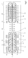
- FIG. 1 is a schematic of a representative assembly with an inventive Conditioning device 1 with a tempering zone 10 shown.
- the Temperature control zone 10 there are at least two stationary transport rollers 11, over which a moisture absorbing endless cloth 12 is stretched.
- the transport rollers 11 are coupled or individually in the same direction in Rotation set.
- the transport rollers 11 drive the moisture-absorbing material Endless cloth 12.
- the Heating device 13 which heats up the surrounding transport rollers 11. The of the Heating device 13 generated heat is on the transport rollers 11 to the moisture receiving endless cloth 12 transferred.
- the print carrier 2 is moved forward by the conditioning device 1.
- a print carrier 2 leaves an upstream one, not shown Print carrier processing device and is in frictional contact along a grid-like Print carrier guide 14 on the moisture absorbing endless cloth 12 and thus comes into thermal and mechanical contact with the heated moisture receiving endless cloth 12 and is also warmed thereby. Through the Condition of the endless cloth 12, and the pressure between the print media 2 and Endless cloth 12 and moisture in the print carrier 2 passes over to the endless cloth 12.
- the heating of the print carrier 2 causes moisture in the print carrier 2 evaporates, which can escape through the grid-like pressure carrier guide 14.
- the moisture absorbed by the moisture-absorbing endless cloth 12 leaves the endless cloth 12 by evaporation on the side facing away from the print carrier 2 and the endless cloth 12 is dried.
- a fan 15 is arranged, the air flow along the Moisture-absorbing endless cloth 12 is produced by at least one horizontally Surface of the endless cloth has directed flow component and thereby the Evaporation process of the moisture absorbing endless cloth 12 and Print media 2 supported.
- At least one Blower 16 the at least one directed perpendicular to the surface of the endless fabric Flow component has between the transport rollers 11, with the advantageously tempered air in and in particular by the moisture receiving endless cloth 12 is blown.
- the blower 16 consists of a plurality of blower units which are evenly distributed over the area between the transport rollers 11 and individually or controlled in groups and regulated in their performance and in particular switched off can be.
- FIG. 1 A particularly advantageous development of the device according to the invention is shown in FIG shown.
- the print carrier 2 will transported only by the endless sheets 12. Due to the symmetrical structure The drying of the print carrier 2 can be improved in an advantageous manner.
- the pressure carrier 2 is from the temperature control zone 10 to an evaporation zone 20 passed on and guided by means of a grid-like pressure carrier guide 21.
- Transport means for the printing medium 2 are preferably used for contact rollers or others known mechanisms, not shown.
- the one coming from the tempering zone 10 Print carrier 2 cools with further release of moisture due to this emitted heat of evaporation.
- the cooling zone 30 is similar to that Tempering zone 10 constructed from transport rollers 31, advantageously two each, over the moisture-absorbing endless cloths 32 are stretched. In this advantageous embodiment, further transport rollers 31 are dispensed with to create the largest possible evaporation area. Between the endless cloths 32 a blower 33 is arranged, which in turn by utilizing the output Evaporation heat the pressure carrier 2 essentially to the initial temperature of the Print carrier 2 cools down before entering the conditioning device 1.
- the pressure carrier 2 is removed from the conditioning device 1 output.
Landscapes
- Engineering & Computer Science (AREA)
- Mechanical Engineering (AREA)
- General Engineering & Computer Science (AREA)
- Textile Engineering (AREA)
- Life Sciences & Earth Sciences (AREA)
- Microbiology (AREA)
- Supply, Installation And Extraction Of Printed Sheets Or Plates (AREA)
- Drying Of Solid Materials (AREA)
- Delivering By Means Of Belts And Rollers (AREA)
- Feeding Of Articles By Means Other Than Belts Or Rollers (AREA)
- Accessory Devices And Overall Control Thereof (AREA)
Abstract
Description
- Figur 1
- schematische Ansicht einer repräsentativen Baugruppe mit einer erfindungsgemäßen Konditioniervorrichtung mit einer Temperierungszone und einer vorteilhaften Gebläsevorrichtung,
- Figur 2
- schematische Ansicht einer repräsentativen Weiterbildung der erfindungsgemäßen Konditioniervorrichtung mit einer Temperierungszone, Verdunstungszone und Kühlzone.
- 1
- Konditioniervorrichtung
- 2
- Druckträger
- 10
- Temperierungszone
- 11
- Transportrolle
- 12
- Feuchtigkeit aufnehmendes Endlostuch
- 13
- Heizeinrichtung
- 14
- Gitterartige Druckträgerführung
- 15
- Gebläse
- 16
- Gebläse
- 20
- Verdunstungszone
- 21
- Gitterartige Druckträgerführung
- 30
- Kühlzone
- 31
- Transportrolle
- 32
- Feuchtigkeit aufnehmendes Endlostuch
- 33
- Gebläse
Claims (20)
- Vorrichtung zum Konditionieren von Druckträgern (2) insbesondere Papierblättern oder Papierbahnen mit einer Temperierungszone (10) in der die Druckträger (2) in Kontakt mit mindestens einem Feuchtigkeit aufnehmenden Endlostuch (12) stehen, mindestens zwei Transportwalzen (11), auf die das Endlostuch aufgespannt ist und mit mindestens einer Heizvorrichtung (13),
dadurch gekennzeichnet, dass das Feuchtigkeit aufnehmende Endlostuch (12) beheizt wird und sich die Heizvorrichtung (13) innerhalb des vom Endlostuch (12) umschlungenen Raums befindet - Vorrichtung nach Anspruch 1,
dadurch gekennzeichnet, dass mindestens eine Heizvorrichtung innerhalb mindestens einer der Transportwalzen (11) angeordnet ist. - Vorrichtung nach einem der Ansprüche 1 bis 2,
dadurch gekennzeichnet, dass ein gitterartige Druckträgerführung (14) auf der vom Endlostuch (12) abgewandten Seite des Druckträgers ausgebildet ist. - Vorrichtung nach einem der Ansprüche 1 bis 2,
dadurch gekennzeichnet, dass ein weiteres Feuchtigkeit aufnehmendes Endlostuch (12) gegenüber dem Transportpfad des Druckträgers (2) angeordnet ist. - Vorrichtung nach einem der Ansprüche 1 bis 4 mit einer Verdunstungszone (20),
dadurch gekennzeichnet, dass sich die Verdunstungszone (20) hinter der Temperierungszone (10) befindet, in der der Druckträger (2) geführt wird und sich der Druckträger (2) zumindest durch die Verdunstung von Feuchtigkeit abkühlt. - Vorrichtung nach Anspruch 5,
dadurch gekennzeichnet, dass es sich bei der Führung in der Verdunstungszone um eine gitterartige Druckträgerführung (21) handelt. - Vorrichtung nach einem der Ansprüche 1 bis 6 mit einer Kühlzone (30) bestehend aus mindestens einem Feuchtigkeit aufnehmenden Endlostuch (32) und mindestens zwei Transportwalzen (31),
dadurch gekennzeichnet, dass sich die Kühlzone (30) hinter der Temperierungszone (10) befindet. - Vorrichtung nach einem der Ansprüche 1 bis 7,
dadurch gekennzeichnet, dass sich der Druckträger (2) beim Transport durch die Kühlzone (30) in Kontakt mit mindestens einem Endlostuch (32) befindet. - Vorrichtung nach einem der Ansprüche 1 bis 8,
dadurch gekennzeichnet, dass wenigstens ein Gebläse (15) so innerhalb der Konditioniervorrichtung (1) angeordnet ist, dass es ein Luftstrom der mindestens eine waagerecht zur Oberfläche des Endlostuchs gerichtete Strömungskomponente aufweist an dem Feuchtigkeit aufnehmenden Endlostuch (12, 32) entlang erzeugt und damit die Verdunstung von Feuchtigkeit aus dem Feuchtigkeit aufnehmenden Endlostuch (12, 32) unterstützt. - Vorrichtung nach einem der Ansprüche 1 bis 9,
dadurch gekennzeichnet, dass wenigstens ein Gebläse (16, 33), das zwischen den Transportwalzen (11, 31) angeordnet ist einen Luftstrom der mindestens eine senkrecht zur Oberfläche des Endlostuchs gerichtete Strömungskomponente aufweist erzeugt, der durch das Feuchtigkeit aufnehmende Endlostuch (12, 32) gepresst wird. - Vorrichtung nach einem der Ansprüche 1 bis 10,
dadurch gekennzeichnet, dass das Feuchtigkeit aufnehmende Endlostuch (12, 32) den Druckträger (2) vorwärts bewegt und dadurch insbesondere eine Relativbewegung zwischen Endlostuch (12, 32) und Druckträger (2) vermieden wird. - Vorrichtung nach einem der Ansprüche 1 bis 11,
dadurch gekennzeichnet, dass das Feuchtigkeit aufnehmende Endlostuch (12, 32) kompressibel ist. - Vorrichtung nach einem der Ansprüche 1 bis 12,
dadurch gekennzeichnet, dass der Luftstrom, von wenigstens einem der von den innerhalb der Konditioniervorrichtung (1) angeordneten Gebläsen (15, 16, 17, 33) erzeugt wird, temperiert ist, insbesondere im Vergleich zum Feuchtigkeit aufnehmenden Endlostuch erwärmt. - Vorrichtung nach einem der Ansprüche 1 bis 13;
dadurch gekennzeichnet, dass die Strömungsgeschwindigkeit des Luftstroms, von wenigstens einem, vorzugsweise aller der von den innerhalb der Konditioniervorrichtung (1) angeordneten Gebläsen (15, 16, 17, 33) erzeugt wird, regelbar ist, insbesondere abschaltbar. - Vorrichtung nach einem der Ansprüche 1 bis 14,
dadurch gekennzeichnet, dass die Heizleistung der Heizeinrichtung (13) über die Länge der Transportrolle variabel ist. - Vorrichtung nach einem der Ansprüche 1 bis 15,
dadurch gekennzeichnet, dass die Heizleistung der Heizeinrichtung (13) innerhalb wenigstens einer, vorzugsweise aller Transportrollen (11) einzeln oder gemeinsam regelbar, insbesondere abschaltbar ist. - Vorrichtung nach einem der Ansprüche 1 bis 16,
dadurch gekennzeichnet, dass der Feuchtigkeitsgehalt des Druckträgers von ca. 10% auf ca. 5 % verringert wird. - Verfahren mit einer Vorrichtung gemäß einem der Ansprüche 1 bis 17,
bestehend aus den Schritten,Erwärmen von Transportrollen (11) mit einer Heizeinrichtung (13),Erwärmen eines Endlostuchs (12), das um die Transportrollen (11) gespannt ist,Erwärmen eines Druckträgers (2) durch Kontakt mit einem Feuchtigkeit aufnehmenden Endlostuch (12),Abgabe der Feuchtigkeit des erwärmten Druckträgers (2) auf ein Feuchtigkeit aufnehmendes Endlostuch (12),Transport des Druckträgers (2) durch eine Temperierungszone (10) durch Kontakt mit dem Endlostuch (12),Ausblasen des Endlostuchs durch ein Gebläse (15, 16). - Verfahren mit einer Vorrichtung gemäß einem der Ansprüche 1 bis 17,
bestehend aus mindestens einem der folgenden Schritte,Erwärmen von Transportrollen (11) mit einer Heizeinrichtung (13),Erwärmen eines Endlostuchs (12), das um die Transportrollen (11) gespannt ist,Erwärmen eines Druckträgers (2) durch Kontakt mit einem Feuchtigkeit aufnehmenden Endlostuch (12),Abgabe der Feuchtigkeit des erwärmten Druckträgers (2) auf ein Feuchtigkeit aufnehmendes Endlostuch (12),Transport des Druckträgers (2) durch eine Temperierungszone (10) durch Kontakt mit dem Endlostuch (12),Ausblasen des Endlostuchs durch ein Gebläse (15, 16),Transport des Druckträgers (2) durch eine Verdunstungszone (20),Abkühlung des Druckträgers (2) in der Verdunstungszone (20) durch Verdunstung. - Verfahren mit einer Vorrichtung gemäß einem der Ansprüche 1 bis 17,
bestehend aus mindestens einem der folgenden Schritte,Erwärmen von Transportrollen (11) mit einer Heizeinrichtung (13),Erwärmen eines Endlostuchs (12), das um die Transportrollen (11) gespannt ist,Erwärmen eines Druckträgers (2) durch Kontakt mit einem Feuchtigkeit aufnehmenden Endlostuch (12),Abgabe der Feuchtigkeit des erwärmten Druckträgers (2) auf ein Feuchtigkeit aufnehmendes Endlostuch (12),Transport des Druckträgers (2) durch eine Temperierungszone (10) durch Kontakt mit dem Endlostuch (12),Ausblasen des Endlostuchs durch ein Gebläse (15, 16),Transport des Druckträgers (2) durch eine Verdunstungszone (20),Abkühlung des Druckträgers (2) in der Verdunstungszone (20) durch Verdunstung,Transport des Druckträgers (2) durch eine Kühlzone (3),Abkühlen des Druckträgers (2) durch Kontakt mit mindestens einem Feuchtigkeit aufnehmenden Endlostuch (32),Ausblasen des Endlostuchs mit einem Gebläse (33),Ausgabe des Druckträgers (2) aus der Konditioniervorrichtung (1).
Applications Claiming Priority (2)
| Application Number | Priority Date | Filing Date | Title |
|---|---|---|---|
| DE10101775A DE10101775A1 (de) | 2001-01-17 | 2001-01-17 | Konditioniervorrichtung zur Veränderung des Feuchtegehalts von Druckträgern |
| DE10101775 | 2001-01-17 |
Publications (2)
| Publication Number | Publication Date |
|---|---|
| EP1225045A2 true EP1225045A2 (de) | 2002-07-24 |
| EP1225045A3 EP1225045A3 (de) | 2004-04-14 |
Family
ID=7670731
Family Applications (1)
| Application Number | Title | Priority Date | Filing Date |
|---|---|---|---|
| EP01129283A Withdrawn EP1225045A3 (de) | 2001-01-17 | 2001-12-13 | Konditioniervorrichtung zur Veränderung des Feuchtgehalts von Druckträgern |
Country Status (7)
| Country | Link |
|---|---|
| US (2) | US6634115B2 (de) |
| EP (1) | EP1225045A3 (de) |
| JP (1) | JP2002301805A (de) |
| CN (1) | CN1365890A (de) |
| CZ (1) | CZ20013723A3 (de) |
| DE (1) | DE10101775A1 (de) |
| HK (1) | HK1048619A1 (de) |
Families Citing this family (11)
| Publication number | Priority date | Publication date | Assignee | Title |
|---|---|---|---|---|
| AU2002303656A1 (en) * | 2002-05-07 | 2003-11-11 | Baldwin Graphic Systems, Inc. | Continuous conditioning system for cleaning a printing press and method of using same |
| DE10356995A1 (de) * | 2003-12-03 | 2005-07-07 | Goss Contiweb B.V. | Rollenrotationsdruckmaschine und Verfahren zur Verringerung von Zugwellen in einer Rollenrotationsdruckmaschine |
| CN103884162B (zh) * | 2014-04-13 | 2016-04-13 | 泰山体育产业集团有限公司 | 一种人造草丝除水装置 |
| CN104908452B (zh) * | 2015-05-29 | 2018-05-01 | 深圳市红源资产管理有限公司 | 用于介质存储的温湿度调节装置及医疗打印机 |
| JP6989926B2 (ja) * | 2018-07-25 | 2022-01-12 | 株式会社ミヤコシ | 乾燥装置及びそれを備えるインクジェット印刷装置 |
| CN112654501B (zh) * | 2018-09-14 | 2022-09-02 | 惠普发展公司,有限责任合伙企业 | 调节辊 |
| CN110561902B (zh) * | 2019-08-29 | 2024-03-29 | 荆门市国弘模具有限公司 | 一种印花台布自动生产系统 |
| CN111252598A (zh) * | 2019-11-19 | 2020-06-09 | 陕西众策网络科技发展有限公司 | 一种产品质量检测分类设备的物料输送装置 |
| CN111121429B (zh) * | 2020-01-15 | 2021-05-11 | 朱振伟 | 一种干燥封边条的装置 |
| CN114654879A (zh) * | 2022-03-17 | 2022-06-24 | 劲标精致科技(深圳)有限公司 | 纸板印刷加工用可自动矫正的印刷面加湿处理装置及方法 |
| CN115556482B (zh) * | 2022-11-09 | 2023-05-05 | 天津宜药印务有限公司 | 一种用于印刷机的烘干装置 |
Family Cites Families (27)
| Publication number | Priority date | Publication date | Assignee | Title |
|---|---|---|---|---|
| DE557770C (de) * | 1931-05-01 | 1932-08-27 | Benno Schilde Maschb Akt Ges | Trockenapparat fuer flaechiges Gut, insbesondere Pappen |
| DE700261C (de) * | 1936-03-01 | 1940-12-17 | Vomag Maschinenfabrik A G | Vorrichtung zum Trocknen des Druckfarbenauftrags auf Papierbahnen oder Bogen, insbesondere fuer Tiefdruckmaschinen |
| DE967544C (de) * | 1952-01-20 | 1957-11-21 | Meteor Appbau Paul Schmeck G M | Trockenmaschine fuer photographische Positive, insbesondere fuer Mattbilder |
| DE1761850A1 (de) * | 1968-07-15 | 1971-10-21 | Feldmuehle Ag | Verfahren zum Herstellen von Faserstoffgebilden |
| US3852980A (en) * | 1971-11-25 | 1974-12-10 | P Zimmer | Apparatus for printing and/or dyeing of high pile webs |
| DE2306383C3 (de) * | 1973-02-09 | 1980-10-23 | Sandco Ltd., Ottawa | Vorrichtung zum Kühlen von Gegenständen |
| FR2303668A1 (fr) * | 1975-03-10 | 1976-10-08 | Sommer Sa | Dispositif refroidisseur pour machine a imprimer les bandes de papier, de textile ou de plastique |
| DE3143089A1 (de) * | 1981-10-30 | 1983-05-26 | Heidelberger Druckmaschinen Ag, 6900 Heidelberg | Vorrichtung zum trocknen von bedruckten bogen an offsetdruckmaschinen |
| FI80101C (fi) * | 1988-05-18 | 1990-04-10 | Tampella Oy Ab | Anordning och foerfarande foer torkning av en fiberbana. |
| MY106607A (en) * | 1988-12-16 | 1995-06-30 | Hewlett Packard Company A Delaware Corp | Heater assembly for printers. |
| US4922627A (en) * | 1989-09-29 | 1990-05-08 | Albany International Corp. | Press drying concept |
| FI88630C (fi) * | 1992-06-08 | 1993-06-10 | Valmet Paper Machinery Inc | Foerfarande och anordning foer att effektivera funktionen av ett yankeepressparti i en mjukpappersmaskin |
| FI96790C (fi) * | 1994-10-11 | 1996-08-26 | Tampella Oy Valmet | Laite kuiturainan kuivaamiseksi ja sileyttämiseksi |
| KR100355339B1 (ko) * | 1994-10-29 | 2002-12-26 | 가부시키가이샤 세이부 기켄 | 고속유체를사용한저온급속탈수건조장치 |
| FI97485C (fi) * | 1995-02-14 | 1996-12-27 | Valmet Corp | Kuivauslaite kuiturainan kuivaamiseksi ja paperikoneen kuivausosa |
| US5666744A (en) * | 1995-11-02 | 1997-09-16 | James River Corporation Of Virginia | Infrared paper drying machine and method for drying a paper web in an infrared paper drying machine |
| FI98080C (fi) * | 1995-11-17 | 1997-04-10 | Valmet Corp | Kuivauslaite kuiturainan kuivaamiseksi |
| FI99272C (fi) * | 1996-04-12 | 1998-02-25 | Valmet Corp | Menetelmä kuiturainan kuivaamiseksi |
| FI99270C (fi) * | 1996-04-12 | 1998-02-25 | Valmet Corp | Menetelmä ja sovitelma kuiturainan kuivatuslaitteen lauhdeveden hyödyntämiseksi |
| FI99271C (fi) * | 1996-04-12 | 1998-02-25 | Valmet Corp | Menetelmä ja sovitelma kuiturainan kuivatuslaitteen energian hyödyntämiseksi |
| DE19614887A1 (de) * | 1996-04-16 | 1997-10-23 | Voith Sulzer Papiermasch Gmbh | Maschine zur Herstellung einer Materialbahn |
| US6182375B1 (en) * | 1996-09-25 | 2001-02-06 | Institute Of Paper Science And Technology, Inc. | Method and apparatus for multi-NIP impulse drying |
| FI104275B (fi) * | 1998-02-18 | 1999-12-15 | Valmet Corp | Menetelmä ja laitteisto kuiturainan kuivaamiseksi |
| US6303003B1 (en) * | 1998-02-24 | 2001-10-16 | David R. Webster | Method and apparatus for drying a moist web |
| DE19918669A1 (de) * | 1999-04-23 | 2000-10-26 | Heidelberger Druckmasch Ag | Trockner mit integrierter Kühleinheit |
| SE516663C2 (sv) * | 1999-06-17 | 2002-02-12 | Metso Paper Karlstad Ab | Torkparti i en maskin för tillverkning av en kontinuerlig tissuepappersbana samt metod för torkning av en kontinuerlig |
| US6158144A (en) * | 1999-07-14 | 2000-12-12 | The Procter & Gamble Company | Process for capillary dewatering of foam materials and foam materials produced thereby |
-
2001
- 2001-01-17 DE DE10101775A patent/DE10101775A1/de not_active Withdrawn
- 2001-10-16 CZ CZ20013723A patent/CZ20013723A3/cs unknown
- 2001-12-13 EP EP01129283A patent/EP1225045A3/de not_active Withdrawn
- 2001-12-20 US US10/028,141 patent/US6634115B2/en not_active Expired - Fee Related
- 2001-12-24 CN CN01144813A patent/CN1365890A/zh active Pending
-
2002
- 2002-01-15 JP JP2002006629A patent/JP2002301805A/ja active Pending
-
2003
- 2003-02-07 HK HK03100882.8A patent/HK1048619A1/zh unknown
- 2003-07-17 US US10/621,995 patent/US6769198B2/en not_active Expired - Fee Related
Also Published As
| Publication number | Publication date |
|---|---|
| US6769198B2 (en) | 2004-08-03 |
| DE10101775A1 (de) | 2002-07-18 |
| EP1225045A3 (de) | 2004-04-14 |
| US6634115B2 (en) | 2003-10-21 |
| CZ20013723A3 (cs) | 2002-09-11 |
| JP2002301805A (ja) | 2002-10-15 |
| US20020100184A1 (en) | 2002-08-01 |
| HK1048619A1 (zh) | 2003-04-11 |
| US20040003512A1 (en) | 2004-01-08 |
| CN1365890A (zh) | 2002-08-28 |
Similar Documents
| Publication | Publication Date | Title |
|---|---|---|
| DE69415443T2 (de) | Infrarotbeheizter Trockner mit Gebläse und Luftabsaugung | |
| DE2323574C3 (de) | Trockenpartie für Papiermaschinen | |
| EP3150378B1 (de) | Anlage und verfahren zur herstellung von wellpappe | |
| EP0677468B1 (de) | Vorrichtung und Verfahren zum Behandeln einer Materialbahn | |
| EP1225045A2 (de) | Konditioniervorrichtung zur Veränderung des Feuchtgehalts von Druckträgern | |
| EP0989232B1 (de) | Trockenpartie | |
| EP0778131B2 (de) | Bogenführsystem für eine Druckmaschine | |
| DE60010399T2 (de) | Flüssige Tinte verwendender Drucker mit einer nicht verbrennenden Trockeneinheit | |
| DE69716601T2 (de) | Verfahren und vorrichtung zur berührungslosen trocknung einer papierbahn oder dergleichen | |
| DE20206407U1 (de) | Druckmaschine mit Trocknungsstation | |
| DE102018121758B4 (de) | Verfahren zur Reduzierung der Welligkeit eines Aufzeichnungsträgers | |
| DE102007035989A1 (de) | System zum Trocknen eines Substrats | |
| DE10359666B4 (de) | Verfahren und Fixiereinrichtung zum Fixieren von Toner auf einem Bedruckstoff | |
| DE2607504B2 (de) | Vorrichtung zum Trocknen von dünnen Materialien in Stücken oder Bahnen im Durchlauf | |
| EP0658427A1 (de) | Trockenvorrichtung | |
| DE112008003825T5 (de) | Pressen- und Trockenpartie einer Bahnbildungsmaschine | |
| DE102021123678B4 (de) | Trocknungseinrichtung in einer Druckmaschine und Druckmaschine mit dieser Trocknungseinrichtung | |
| DE602005003544T2 (de) | Luftgekühltes thermisches Aktivierungsgerät | |
| EP1830146B1 (de) | Vorrichtung und Verfahren zur Wärmebehandlung von textilen Warenbahnen | |
| DE102020110912B4 (de) | Verfahren zum Trocknen eines Bestrahlungsguts und Infrarot-Bestrahlungsvorrichtung zur Durchführung des Verfahrens | |
| DE19934487A1 (de) | Durchlauftrockner für Platten oder Bahnen | |
| DE19847181C2 (de) | Verfahren zum Trocknen von im Siebdruckverfahren bedruckten Druckfarbenträgern | |
| DE2615261A1 (de) | Vorrichtung zum behandeln von bahnfoermigem material | |
| DE19926749B4 (de) | Farbwerk für eine Druckmaschine | |
| DE19826063A1 (de) | Kühleinrichtung für eine Materialbahn |
Legal Events
| Date | Code | Title | Description |
|---|---|---|---|
| PUAI | Public reference made under article 153(3) epc to a published international application that has entered the european phase |
Free format text: ORIGINAL CODE: 0009012 |
|
| AK | Designated contracting states |
Kind code of ref document: A2 Designated state(s): AT BE CH CY DE DK ES FI FR GB GR IE IT LI LU MC NL PT SE TR |
|
| AX | Request for extension of the european patent |
Free format text: AL;LT;LV;MK;RO;SI |
|
| PUAL | Search report despatched |
Free format text: ORIGINAL CODE: 0009013 |
|
| AK | Designated contracting states |
Kind code of ref document: A3 Designated state(s): AT BE CH CY DE DK ES FI FR GB GR IE IT LI LU MC NL PT SE TR |
|
| AX | Request for extension of the european patent |
Extension state: AL LT LV MK RO SI |
|
| RIC1 | Information provided on ipc code assigned before grant |
Ipc: 7F 26B 13/10 B Ipc: 7F 26B 13/26 B Ipc: 7G 03D 15/02 B Ipc: 7B 41F 23/04 A |
|
| RAP1 | Party data changed (applicant data changed or rights of an application transferred) |
Owner name: EASTMAN KODAK COMPANY |
|
| AKX | Designation fees paid | ||
| REG | Reference to a national code |
Ref country code: DE Ref legal event code: 8566 |
|
| STAA | Information on the status of an ep patent application or granted ep patent |
Free format text: STATUS: THE APPLICATION IS DEEMED TO BE WITHDRAWN |
|
| 18D | Application deemed to be withdrawn |
Effective date: 20041015 |