EP1223368B1 - Steuerung einer Berghaltevorrichtung für ein Kraftfahrzeug - Google Patents
Steuerung einer Berghaltevorrichtung für ein Kraftfahrzeug Download PDFInfo
- Publication number
- EP1223368B1 EP1223368B1 EP01128243A EP01128243A EP1223368B1 EP 1223368 B1 EP1223368 B1 EP 1223368B1 EP 01128243 A EP01128243 A EP 01128243A EP 01128243 A EP01128243 A EP 01128243A EP 1223368 B1 EP1223368 B1 EP 1223368B1
- Authority
- EP
- European Patent Office
- Prior art keywords
- vehicle
- bypass clutch
- clutch
- judged
- detecting
- Prior art date
- Legal status (The legal status is an assumption and is not a legal conclusion. Google has not performed a legal analysis and makes no representation as to the accuracy of the status listed.)
- Expired - Lifetime
Links
Images


Classifications
-
- F—MECHANICAL ENGINEERING; LIGHTING; HEATING; WEAPONS; BLASTING
- F16—ENGINEERING ELEMENTS AND UNITS; GENERAL MEASURES FOR PRODUCING AND MAINTAINING EFFECTIVE FUNCTIONING OF MACHINES OR INSTALLATIONS; THERMAL INSULATION IN GENERAL
- F16H—GEARING
- F16H61/00—Control functions within control units of change-speed- or reversing-gearings for conveying rotary motion ; Control of exclusively fluid gearing, friction gearing, gearings with endless flexible members or other particular types of gearing
- F16H61/0059—Braking of gear output shaft using simultaneous engagement of friction devices applied for different gear ratios
-
- F—MECHANICAL ENGINEERING; LIGHTING; HEATING; WEAPONS; BLASTING
- F16—ENGINEERING ELEMENTS AND UNITS; GENERAL MEASURES FOR PRODUCING AND MAINTAINING EFFECTIVE FUNCTIONING OF MACHINES OR INSTALLATIONS; THERMAL INSULATION IN GENERAL
- F16H—GEARING
- F16H61/00—Control functions within control units of change-speed- or reversing-gearings for conveying rotary motion ; Control of exclusively fluid gearing, friction gearing, gearings with endless flexible members or other particular types of gearing
- F16H61/20—Preventing gear creeping ; Transmission control during standstill, e.g. hill hold control
-
- B—PERFORMING OPERATIONS; TRANSPORTING
- B60—VEHICLES IN GENERAL
- B60W—CONJOINT CONTROL OF VEHICLE SUB-UNITS OF DIFFERENT TYPE OR DIFFERENT FUNCTION; CONTROL SYSTEMS SPECIALLY ADAPTED FOR HYBRID VEHICLES; ROAD VEHICLE DRIVE CONTROL SYSTEMS FOR PURPOSES NOT RELATED TO THE CONTROL OF A PARTICULAR SUB-UNIT
- B60W30/00—Purposes of road vehicle drive control systems not related to the control of a particular sub-unit, e.g. of systems using conjoint control of vehicle sub-units, or advanced driver assistance systems for ensuring comfort, stability and safety or drive control systems for propelling or retarding the vehicle
- B60W30/18—Propelling the vehicle
- B60W30/18009—Propelling the vehicle related to particular drive situations
- B60W30/18109—Braking
- B60W30/18118—Hill holding
-
- F—MECHANICAL ENGINEERING; LIGHTING; HEATING; WEAPONS; BLASTING
- F16—ENGINEERING ELEMENTS AND UNITS; GENERAL MEASURES FOR PRODUCING AND MAINTAINING EFFECTIVE FUNCTIONING OF MACHINES OR INSTALLATIONS; THERMAL INSULATION IN GENERAL
- F16H—GEARING
- F16H61/00—Control functions within control units of change-speed- or reversing-gearings for conveying rotary motion ; Control of exclusively fluid gearing, friction gearing, gearings with endless flexible members or other particular types of gearing
- F16H61/20—Preventing gear creeping ; Transmission control during standstill, e.g. hill hold control
- F16H2061/205—Hill hold control, e.g. with torque converter or a friction device slightly engaged to keep vehicle stationary
-
- F—MECHANICAL ENGINEERING; LIGHTING; HEATING; WEAPONS; BLASTING
- F16—ENGINEERING ELEMENTS AND UNITS; GENERAL MEASURES FOR PRODUCING AND MAINTAINING EFFECTIVE FUNCTIONING OF MACHINES OR INSTALLATIONS; THERMAL INSULATION IN GENERAL
- F16H—GEARING
- F16H2312/00—Driving activities
- F16H2312/04—Holding or hillholding
-
- F—MECHANICAL ENGINEERING; LIGHTING; HEATING; WEAPONS; BLASTING
- F16—ENGINEERING ELEMENTS AND UNITS; GENERAL MEASURES FOR PRODUCING AND MAINTAINING EFFECTIVE FUNCTIONING OF MACHINES OR INSTALLATIONS; THERMAL INSULATION IN GENERAL
- F16H—GEARING
- F16H59/00—Control inputs to control units of change-speed-, or reversing-gearings for conveying rotary motion
- F16H59/60—Inputs being a function of ambient conditions
- F16H59/66—Road conditions, e.g. slope, slippery
-
- Y—GENERAL TAGGING OF NEW TECHNOLOGICAL DEVELOPMENTS; GENERAL TAGGING OF CROSS-SECTIONAL TECHNOLOGIES SPANNING OVER SEVERAL SECTIONS OF THE IPC; TECHNICAL SUBJECTS COVERED BY FORMER USPC CROSS-REFERENCE ART COLLECTIONS [XRACs] AND DIGESTS
- Y10—TECHNICAL SUBJECTS COVERED BY FORMER USPC
- Y10S—TECHNICAL SUBJECTS COVERED BY FORMER USPC CROSS-REFERENCE ART COLLECTIONS [XRACs] AND DIGESTS
- Y10S477/00—Interrelated power delivery controls, including engine control
- Y10S477/901—Control signal is slope
Definitions
- the present invention relates to a hill hold control apparatus for a vehicle and more particularly to a hill hold control apparatus capable of locking wheels when a selector lever of an automatic transmission is positioned at "forward or reverse drive" range.
- JP-A-2000-65199 discloses an automatic transmission for an automobile comprising an input shaft having a plurality of drive gears, an output shaft having a plurality of driven gears paired with respective drive gears and a bypass clutch for engaging the input shaft with the output shaft.
- This type of automatic transmission has an advantage in that the rotation speed of the output shaft can be synchronized with the engine speed and shift shocks at up-shifting can be reduced by preventing so-called "torque drop" by transmitting torque through the bypass clutch in high speed shift stages.
- this type automatic transmission in case where a friction clutch is used as a start clutch for engaging a crank shaft with the input shaft, has a problem that when the vehicle attempts to start forward on a grade, the vehicle reverses, while a driver shifts his or her foot from a brake pedal to an accelerator pedal and the friction clutch which has been released at stopping is engaged again.
- JP-A-2000-127928 discloses a hill hold control apparatus capable of locking wheels by a brake system when the select lever of an automatic transmission is selected at a forward drive position and specified conditions are satisfied.
- this hill hold apparatus needs to incorporate an accumulator and an electromagnetic operative opening and closing valve in the apparatus, this leading to an increase of the number of components and manufacturing cost.
- EP-A- 0367020 and DE 43 16 784 A are referred to.
- reference numeral 10 denotes an automatic transmission having an input shaft 11 and an output shaft 12.
- a main clutch (start clutch) 15 between a crankshaft 14 of an engine 13 and an input shaft 11.
- start clutch 15 When the main clutch 15 is engaged, the rotation of the crankshaft 14 is transmitted to the input shaft 11 and when the main clutch 15 is released, the power transmission stops.
- the main clutch 15 is driven by a hydraulically operated actuator.
- Drive gears 21 to 25 for the 1 st gear ratio to the 5 th gear ratio respectively are mounted on the input shaft 11 and driven gears 31 to 35 for the 1 st gear ratio to the 5 th gear ratio respectively are mounted on the output shaft 12.
- the respective driven gears 31 to 35 mesh with the respective drive gears 21 to 25, constituting respective shift gear trains from 1 st to 5 th gear ratios.
- a drive gear 26 for reverse speed is mounted on the input shaft 11 and meshes with a driven gear 36 which is mounted on the output shaft 12 through an idle gear 27.
- These drive gear 26, driven gear 36 and idle gear 27 constitute a reverse gear train.
- dog clutches 21a to 26a for the respective drive gears 21 to 26 on the input shaft 11.
- the changeover mechanism is actuated by a hydraulically operated actuator to select a shift gear train.
- a drive side bypass gear 28 is rotatably mounted on the input shaft 11 and a driven side bypass gear 38 meshing with the bypass gear 28 is fixed to the output shaft 12. Further, a bypass clutch (auxiliary clutch) 29 is mounted on the input shaft 11.
- the bypass clutch 29 is a wet type multiple disc clutch which can be operated in an engagement condition, in a partially engaged condition and in a released condition. This bypass clutch 29 can prevent "torque drop" at shifting by being engaged when the gear is up-shifted.
- This bypass clutch 29 may mounted on the output shaft 12 or may be mounted on an intermediate shaft other than the input and output shafts 11, 12.
- the bypass clutch 29 is actuated by an hydraulically operated actuator.
- a hill hold control can be performed by engaging the bypass clutch 29 on a grade.
- the gear train of the 1 st gear ratio is in a power transmitting condition and at the same time the bypass clutch 29 is engaged.
- the shift gear train used when the hill hold control is performed may be a gear train for the 1 st gear ratio or a gear train for the 2 nd gear ratio.
- the hill hold control can be performed by electronically detecting the selected shift gear train of the 1 st gear ratio, 2 nd gear ratio or reverse speed and controlling a hydraulic pressure to the actuator.
- the hill hold control is assisted by an electronic control, by releasing the bypass clutch 29 according to the positions of the shift gear trains and operations of miscellaneous pedals, the vehicle can roll forward or rearward freely and by calculating a gradient angle of the vehicle or output torque, the vehicle can start smoothly.
- reference numeral 40 denotes a control unit having a CPU and memories.
- the control unit 40 sends control signals to a main clutch actuator 41 for actuating the main clutch 15, a gear shift actuator 42 for changing over the shift gear train by actuating the dog clutches 21a to 26a, a bypass clutch actuator 43 for actuating the bypass clutch 29.
- Working fluid is supplied from a hydraulic pump driven by a pump drive motor 44 to these actuators 41 to 43.
- the pump drive motor 44 is controlled by signals from the control unit 40.
- the pressure of working fluid discharged from the hydraulic pump is detected by a hydraulic pressure sensor 45.
- the gear shift position (gear train position) is detected by a gear shift position sensor 46.
- the clutch stroke of the main clutch 15 is detected by a main clutch sensor 47. Signals from the respective sensors are sent to the control unit 40.
- the hydraulic pump may be driven by an engine not by the motor 44.
- miscellaneous ranges such as Drive “D” range and Reverse “R” range are selected .
- a selector lever position sensor 48 for detecting a selected range and there is provided a foot brake switch 49 for detecting whether or not a foot brake has been operated by the driver.
- a parking brake switch 50 for detecting whether or not a parking brake has been operated. Respective detecting signals are sent to the control unit 40.
- an ignition key switch 51 sends a signal to the control unit 40.
- the control unit 40 sends an operating signal to a starter motor 52.
- a signal from an accelerator pedal opening angle sensor 53 for detecting the depressing amount of an accelerator pedal is sent to the control unit 40.
- the control unit 40 sends a control signal to an electronic throttle valve control apparatus (ETC) 54.
- ETC electronic throttle valve control apparatus
- the control unit 40 receives detecting signals from an input and output shaft speed sensor 55 for detecting the revolution speed of the input and output shafts, from a vehicle speed sensor 56 for detecting vehicle speeds and from an acceleration sensor 57 for detecting lateral acceleration of the vehicle.
- Fig. 3 is a flowchart showing steps of a hill hold control of an automatic transmission of Fig. 1.
- a step S1 it is judged whether or not a vehicle travels on a grade. This judgment can be made by a known method. For example, whether or not a vehicle travels on a grade is judged based on respective detecting signals from a gear shift position sensor 46, a vehicle speed sensor 56, an acceleration sensor 57, an input and output shaft rotation speed sensor 55 and the like or the judgment is made based on a signal from an incline angle sensor.
- the shift gear train is a start gear train.
- the start gear train is either of shift gear trains, 1 st gear ratio, 2 nd gear ratio and reverse speed.
- the 1 st gear ratio or the 2 nd gear ratio are automatically selected according to the vehicle traveling situations.
- a shift gear train of reverse speed is selected.
- an engagement condition of the bypass clutch 29 is judged from a flag.
- the program goes to a step S4 where it is judged whether or not a foot brake is depressed by detecting an ON or OFF operation of the foot brake switch 49.
- the program goes to a step S5 where it is judged whether or not the vehicle stops or the vehicle is in standstill.
- the program goes to a step S6 where the bypass clutch 29 is engaged and at a step S7 a clutch flag F clutch is set to 1 (it means that bypass clutch is engaged).
- the hill hold routine has been executed and wheels are locked. For example, after the foot brake is depressed with the selector lever set to "D" range and the vehicle stops on a grade, even when the driver takes his or her foot from the foot brake pedal, the wheels are locked by the hill hold control and the vehicle is held in standstill. Then, when the vehicle stops with a start gear train selected, the main clutch 15 is controlled in a released condition, unless the vehicle is equipped with an automatic stopping and starting system.
- the program goes to a step S10 where the bypass clutch 29 is released and at a step S11 the clutch flag is set to a released condition (0).
- the step S4 in case where it is judged that a foot brake is depressed, the step 12 is executed and the bypass clutch 29 is established to a partially engaged condition. In this case, the routine finishes without changing the clutch flag.
- the program goes to a step S8 where the state of the accelerator pedal is detected based on a signal from the accelerator pedal opening angle sensor 53.
- the program goes to the step S6 where the hill hold control is maintained and if it is judged that the accelerator pedal is open, the program goes to a step S9 where it is judged whether the vehicle stops or travels.
- the program goes to the step S10 and in case where it is judged that the vehicle is in standstill, the start routine is executed. That is, when the accelerator pedal is depressed while the vehicle is in standstill, the start routine is executed.
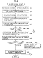
- Fig. 4 is a flowchart showing a start routine.
- a road surface gradient ⁇ of the grade is estimated.
- the road surface gradient ⁇ may be calculated from driving force and vehicle speed or may be calculated by a signal from the incline angle sensor.
- an engine output torque is calculated based on signal from an engine speed sensor and the like according to a known method.
- the program goes to S16 where the condition of engagement of the main clutch, namely, the clutch stroke is detected based on a signal of the main clutch sensor 47 and at a step S17 an output torque Tout of the automatic transmission is calculated based on the engine output torque obtained at the step S15, the engagement condition of the main clutch obtained at the step S16 and the gear ratio detected by the gear shift position sensor 46.
- the start torque T st calculated at the step S14 is compared with the output torque T out calculated at the step S17. If the start torque T st is larger than Tout, it is judged that the vehicle can start and if not it is judged that the vehicle can not start. In case where the vehicle can start, at a step S19, a hydraulic pressure P bd necessary for releasing the bypass clutch is calculated.
- a calorific value Q of the bypass clutch 29 is estimated and at a step S21 the calorific value Q is compared with a seizure limit calorific value of the bypass clutch 29 which is stored in the memory.
- the seizure limit calorific value is determined by experiments beforehand. In case where it is judged that the calorific value Q is within an allowable range, the program goes to a step S22. On the other hand, in case where it is judged that the calorific value Q is too much, the program goes to a step S23 where a reduction of engine output is required to the engine control unit. Then, at a step S22 hydraulic pressure of the bypass clutch 29 is outputted to the control unit. Thus, in case where there is fear of seizure in the bypass clutch 29, the engine output gradually goes down to prevent seizure.
- the calorific value Q becomes larger as the required hydraulic pressure is large, that is, the gradient is large. Further, the calorific value Q becomes larger with an increase of the number of rotation difference of the bypass clutch. In case of an excessive calorific value Q, the requirement of torque reduction continues to be issued and as a result the vehicle can not start. However, this is a very rare case in which the gradient exceeds far away 30 %.
- a greatest feature of the hill hold apparatus according to the present invention is that a hill hold can be realized only by hydraulically controlling an existing bypass clutch 29. Therefore, the hill hold apparatus does not require to incorporate any special devices such as brake piping, an accumulator and the like. Further, since the hill hold apparatus according to the present invention can perform a hill hold control based on road conditions, the vehicle can start smoothly without stepping back on a grade. Further, since the hill hold apparatus can start the vehicle within an allowable limit of calorific value of the bypass clutch, the drive train is prevented from being damaged by overloads.
- Fig. 5 is a flowchart showing steps of a hill hold control according to another embodiment. Since steps S31 to S42 of Fig. 5 correspond to steps S1 to S12 of Fig. 3, respectively, descriptions of respective steps S31 to S42 are omitted.
- the program goes to a step S43 where it is judged whether or not the parking brake is operative. If it is judged that the parking brake is operative, the program goes to a step S44 where it is judged whether or not the vehicle is in standstill. In case where it is judged that the vehicle is in standstill, at a step S42, the bypass clutch 29 is set to a partially engaged condition.
- the program leaves the routine without changing the clutch flag.
- the program goes to a step S36 where the bypass clutch is set to an engaged condition.
- the hill hold control is available with the bypass clutch 29 partially engaged.
- the start routine shown in Fig. 4 is carried out.
- the control method shown in Fig. 5 when the parking brake is operative, since the bypass clutch can be partially engaged, the working pressure of the bypass clutch 29 can be reduced and as a result fuel consumption can be saved.
Claims (5)
- Berganfahrsteuerungsvorrichtung für ein Fahrzeug mit Automatikgetriebe (10) mit mehreren auf einer Eingangswelle (11) montierten antreibenden Zahnrädern (21-26), mehreren auf einer Ausgangswelle (12) montierten und mit den antreibenden Zahnrädern jeweils kämmenden angetriebenen Zahnrädern (31-36) und einer Umgehungskupplung (29) zum Ineingriffbringen der Eingangswelle mit der Ausgangswelle;
gekennzeichnet durch:eine Fahrzeuggeschwindigkeitserfassungseinrichtung zum Erfassen einer Fahrzeuggeschwindigkeit;eine Steigungsentscheidungseinrichtung zum Entscheiden, ob das Fahrzeug sich auf einer Steigung befindet;eine Schaltgetriebezugerfassungseinrichtung (48) zum Erfassen eines Schaltgetriebezugs des Automatikgetriebes; undeine Steuereinrichtung (40), die dazu geeignet ist, die Umgehungskupplung vollständig einzurücken, wenn basierend auf Signalen der Fahrzeuggeschwindigkeitserfassungseinrichtung, der Steigungsentscheidungseinrichtung und der Schaltgetriebezugerfassungseinrichtung entschieden wird, dass das Fahrzeug sich auf einer Steigung im Stillstand befindet und der Schaltgetriebezug der Anfahrgetriebezug ist. - Vorrichtung nach Anspruch 1, ferner mit:einer Fußbremsenbetätigungserfassungseinrichtung (49) zum Erfassen einer Betätigung einer Fußbremse;wobei die Steuereinrichtung die Umgehungskupplung vollständig einrückt, wenn basierend auf der Fußbremsenbetätigung entschieden wird, dass die Fußbremse nicht betätigt ist; unddie Umgehungskupplung teilweise einrückt, wenn basierend auf der Fußbremsenbetätigung entschieden wird, dass die Fußbremse betätigt ist.
- Vorrichtung nach Anspruch 1, ferner mit:einer Parkbremsenbetätigungserfassungseinrichtung (50) zum Erfassen einer Betätigung der Parkbremse;wobei die Steuereinrichtung (40) die Umgehungskupplung vollständig einrückt, wenn basierend auf der Parkbremsenbetätigung entschieden wird, dass die Parkbremse nicht betätigt ist; unddie Umgehungskupplung teilweise einrückt, wenn basierend auf der Parkbremsenbetätigung entschieden wird, dass die Parkbremse betätigt ist.
- Vorrichtung nach Anspruch 1, 2 oder 3, ferner mit:einer Straßengradientenschätzeinrichtung zum Schätzen eines Straßenoberflächengradienten einer Straße, auf der das Fahrzeug sich im Stillstand befindet;einer Anfahrdrehmomentberechnungseinrichtung zum Berechnen eines zum Anfahren des Fahrzeugs erforderlichen Anfahrdrehmoments basierend auf dem Straßenoberflächengradienten;einer Ausgangsdrehmomentberechnungseinrichtung zum Berechnen eines Ausgangsdrehmoments basierend auf dem Motordrehmoment und dem Einrückzustand der Hauptkupplung; undeiner Umgehungskupplungausrückeinrichtung (43) zum Ausrücken der Umgehungskupplung, wenn das Ausgangsdrehmoment das für das Anfahren des Fahrzeugs benötigte Anfahrdrehmoment überschreitet.
- Vorrichtung nach einem der Ansprüche 1 bis 4, ferner mit:einer Heizwertberechnungseinrichtung zum Berechnen eines Heizwertes der Umgehungskupplung; undeiner Motorleistungsverminderungseinrichtung (54) zum Vermindern der Motorleistung, wenn der Heizwert einen Schwellenwert überschreitet.
Applications Claiming Priority (2)
| Application Number | Priority Date | Filing Date | Title |
|---|---|---|---|
| JP2000360516 | 2000-11-28 | ||
| JP2000360516A JP2002168333A (ja) | 2000-11-28 | 2000-11-28 | 自動車のヒルホールド制御装置 |
Publications (3)
| Publication Number | Publication Date |
|---|---|
| EP1223368A2 EP1223368A2 (de) | 2002-07-17 |
| EP1223368A3 EP1223368A3 (de) | 2004-08-11 |
| EP1223368B1 true EP1223368B1 (de) | 2006-04-19 |
Family
ID=18832101
Family Applications (1)
| Application Number | Title | Priority Date | Filing Date |
|---|---|---|---|
| EP01128243A Expired - Lifetime EP1223368B1 (de) | 2000-11-28 | 2001-11-28 | Steuerung einer Berghaltevorrichtung für ein Kraftfahrzeug |
Country Status (4)
| Country | Link |
|---|---|
| US (1) | US6616572B2 (de) |
| EP (1) | EP1223368B1 (de) |
| JP (1) | JP2002168333A (de) |
| DE (1) | DE60118875T2 (de) |
Cited By (1)
| Publication number | Priority date | Publication date | Assignee | Title |
|---|---|---|---|---|
| CN107618522A (zh) * | 2017-09-12 | 2018-01-23 | 中国神华能源股份有限公司 | 列车限制坡道起动操纵提示系统 |
Families Citing this family (34)
| Publication number | Priority date | Publication date | Assignee | Title |
|---|---|---|---|---|
| WO2003040594A1 (fr) * | 2001-11-08 | 2003-05-15 | Hitachi, Ltd. | Dispositif de commande d'unite de changement de vitesse de type engrenage, procede de commande et automobile |
| FR2838083B1 (fr) * | 2002-04-03 | 2004-07-02 | Peugeot Citroen Automobiles Sa | Procede de gestion de la stabilite en pente d'un vehicule automobile equipe d'un embrayage pilote |
| JP3612711B2 (ja) * | 2002-07-03 | 2005-01-19 | トヨタ自動車株式会社 | 自動車 |
| JP2004278767A (ja) * | 2003-03-19 | 2004-10-07 | Suzuki Motor Corp | 車両用自動変速機の制御装置 |
| DE10320775A1 (de) * | 2003-05-09 | 2004-12-02 | Zf Friedrichshafen Ag | Verfahren zum Steuern eines Automatgetriebes mit einer Anfahrkupplung und mehreren Schaltelementen |
| DE202004000706U1 (de) | 2004-01-16 | 2004-05-13 | Herm. Friedr. Künne Gmbh & Co. | Profilschienensystem zur Überprüfung von Bodenbelagsübergängen |
| JP4621969B2 (ja) * | 2004-05-28 | 2011-02-02 | スズキ株式会社 | 自動変速機の制御装置 |
| DE102005001550A1 (de) * | 2005-01-13 | 2006-07-27 | Zf Friedrichshafen Ag | Verfahren zur Anfahrsteuerung eines Kraftfahrzeugs |
| US7166060B2 (en) * | 2005-01-18 | 2007-01-23 | Ford Global Technologies, Llc. | Hill hold for a vehicle |
| US7509202B2 (en) * | 2006-01-17 | 2009-03-24 | General Motors Corporation | Neutral idle hill detection |
| US7853388B2 (en) * | 2006-02-23 | 2010-12-14 | Siemens Industry, Inc. | Devices, systems, and methods for controlling a braking system |
| US8620498B2 (en) * | 2006-06-20 | 2013-12-31 | GM Global Technology Operations LLC | Hybrid road grade determination system |
| JP4127310B2 (ja) * | 2006-12-27 | 2008-07-30 | トヨタ自動車株式会社 | 車両の制御装置、制御方法、その方法を実現するプログラムおよびそのプログラムを記録した記録媒体 |
| JP2008309267A (ja) * | 2007-06-15 | 2008-12-25 | Jatco Ltd | 自動変速機の制御装置 |
| FR2921882B1 (fr) * | 2007-10-03 | 2009-12-04 | Renault Sas | Dispositif d'assistance aux manoeuvres de montee d'une pente d'un vehicule automobile |
| DE102007055085B4 (de) * | 2007-11-16 | 2019-02-21 | Getrag-Ford Transmissions Gmbh | Verfahren zum Verhindern eines unkontrollierten Rückrollens |
| JP4957528B2 (ja) * | 2007-12-03 | 2012-06-20 | 日産自動車株式会社 | 容量制御式発進クラッチ付き変速機搭載車両の高応答発進制御装置 |
| US20090187324A1 (en) | 2008-01-23 | 2009-07-23 | Jianbo Lu | Vehicle Stability Control System and Method |
| JP5272654B2 (ja) * | 2008-10-30 | 2013-08-28 | 井関農機株式会社 | トラクタの走行伝動装置 |
| US8880288B2 (en) * | 2009-06-16 | 2014-11-04 | Robert Bosch Gmbh | Determining low-speed driving direction in a vehicle |
| DE102010003510B4 (de) * | 2010-03-31 | 2022-11-17 | Zf Friedrichshafen Ag | Verfahren zum Betreiben eines Antriebsstrangs |
| JP5700779B2 (ja) * | 2010-11-24 | 2015-04-15 | Udトラックス株式会社 | 車両の発進制御システム |
| DE102013000838A1 (de) | 2013-01-21 | 2014-07-24 | Getrag Getriebe- Und Zahnradfabrik Hermann Hagenmeyer Gmbh & Cie Kg | Verfahren zum Halten eines Kraftfahrzeuges an einer Steigung |
| US9126597B2 (en) | 2013-03-14 | 2015-09-08 | Robert Bosch Gmbh | Hill hold decay |
| GB2525595B (en) * | 2014-04-28 | 2016-12-14 | Caterpillar Sarl | Braking system and method for machine |
| JP2016061409A (ja) * | 2014-09-19 | 2016-04-25 | アイシン精機株式会社 | ヒルホールド装置及びヒルホールド方法 |
| US9995391B2 (en) * | 2015-09-24 | 2018-06-12 | Hyundai Motor Company | Control method for preventing backward slipping of vehicle |
| DE102016202693A1 (de) | 2016-02-22 | 2017-08-24 | Audi Ag | Schutzvorrichtung für einen Antriebsstrang eines Kraftfahrzeugs |
| US9809207B2 (en) | 2016-02-23 | 2017-11-07 | Honda Motor Co., Ltd. | Vehicle control system |
| US9821778B2 (en) | 2016-02-23 | 2017-11-21 | Honda Motor Co., Ltd. | Vehicle control system |
| DE102018206204B4 (de) * | 2018-04-23 | 2021-05-06 | Zf Friedrichshafen Ag | Verfahren zum Halten eines Fahrzeugs am Berg |
| US10670142B1 (en) * | 2018-11-19 | 2020-06-02 | Schaeffler Technologies AG & Co. KG | Hybrid module including a torque converter bypass clutch |
| JP7347365B2 (ja) * | 2020-08-06 | 2023-09-20 | トヨタ自動車株式会社 | 摩擦係合要素の熱負荷推定装置 |
| CN112943915B (zh) * | 2021-03-19 | 2022-08-23 | 潍柴动力股份有限公司 | 一种坡道起步控制方法及车辆 |
Family Cites Families (10)
| Publication number | Priority date | Publication date | Assignee | Title |
|---|---|---|---|---|
| EP0367020B1 (de) * | 1988-10-31 | 1992-12-23 | Volkswagen Aktiengesellschaft | Verfahren zum Schalten eines Stufenwechselgetriebes |
| US5172797A (en) * | 1992-01-24 | 1992-12-22 | Eaton Corporation | Motor vehicle inertia and hill holding braking mechanism |
| DE4316784C2 (de) * | 1993-05-19 | 1997-02-06 | Getrag Getriebe Zahnrad | Antriebseinheit für Kraftfahrzeuge |
| JP2878964B2 (ja) * | 1994-05-02 | 1999-04-05 | アイシン・エィ・ダブリュ株式会社 | 自動変速機の制御方法及び制御装置 |
| KR970046648A (ko) * | 1995-12-19 | 1997-07-26 | 전성원 | 경사로 밀림 방지기능을 구비한 반자동 변속 제어장치 및 그 방법 |
| JP3039367B2 (ja) * | 1996-03-27 | 2000-05-08 | アイシン・エィ・ダブリュ株式会社 | 自動変速機の制御装置 |
| JP3601276B2 (ja) * | 1997-12-08 | 2004-12-15 | アイシン・エィ・ダブリュ株式会社 | 自動変速機の制御装置 |
| US5943911A (en) * | 1998-05-11 | 1999-08-31 | Borg-Warner Automotive, Inc. | Electromechanical friction clutch control for a manual transmission |
| JP2000065199A (ja) | 1998-08-12 | 2000-03-03 | Hitachi Ltd | 自動変速機の制御装置および制御方法 |
| JP2000127928A (ja) | 1998-10-22 | 2000-05-09 | Toyota Motor Corp | 車両のヒルホールド制御装置 |
-
2000
- 2000-11-28 JP JP2000360516A patent/JP2002168333A/ja active Pending
-
2001
- 2001-11-27 US US09/994,018 patent/US6616572B2/en not_active Expired - Fee Related
- 2001-11-28 EP EP01128243A patent/EP1223368B1/de not_active Expired - Lifetime
- 2001-11-28 DE DE60118875T patent/DE60118875T2/de not_active Expired - Fee Related
Cited By (1)
| Publication number | Priority date | Publication date | Assignee | Title |
|---|---|---|---|---|
| CN107618522A (zh) * | 2017-09-12 | 2018-01-23 | 中国神华能源股份有限公司 | 列车限制坡道起动操纵提示系统 |
Also Published As
| Publication number | Publication date |
|---|---|
| DE60118875T2 (de) | 2006-09-07 |
| EP1223368A2 (de) | 2002-07-17 |
| EP1223368A3 (de) | 2004-08-11 |
| DE60118875D1 (de) | 2006-05-24 |
| US6616572B2 (en) | 2003-09-09 |
| JP2002168333A (ja) | 2002-06-14 |
| US20020065170A1 (en) | 2002-05-30 |
Similar Documents
| Publication | Publication Date | Title |
|---|---|---|
| EP1223368B1 (de) | Steuerung einer Berghaltevorrichtung für ein Kraftfahrzeug | |
| US7544149B2 (en) | Shift control apparatus and shift control method of automatic transmission of vehicle | |
| US8260510B2 (en) | Control apparatus and control method for transmission | |
| JP4663840B2 (ja) | 自動変速機のエンジンオーバーラン防止装置 | |
| EP1134111B1 (de) | Steuerung für automatische Fahrzeuggetriebe | |
| US20190193736A1 (en) | Automatic transmission and control method of the same | |
| JP3675341B2 (ja) | 車両用駆動装置 | |
| EP1310696B1 (de) | Steuereinrichtung einer automatischen Kupplung | |
| EP1443248B1 (de) | Getriebe mit einer Steuereinheit | |
| JP5653694B2 (ja) | 車両のクリープトルク制御装置 | |
| JP4100057B2 (ja) | 変速制御装置 | |
| JP3496467B2 (ja) | 車両用定速走行装置 | |
| JP4706138B2 (ja) | 車両の坂道発進補助装置 | |
| JP4042290B2 (ja) | 自動クラッチのクリープ制御装置 | |
| JP5868585B2 (ja) | 車両用走行制御装置 | |
| JP3797220B2 (ja) | 車両の自動変速装置 | |
| JP4415291B2 (ja) | 車両の自動変速装置 | |
| GB2392968A (en) | Clutch control system for automatically controlling a friction clutch in a motor vehicle | |
| JP3893842B2 (ja) | 車両のオートクラッチ制御装置 | |
| JP4221957B2 (ja) | 変速制御装置 | |
| JPH0243048B2 (de) | ||
| JP3619854B2 (ja) | 車両用自動変速機の変速制御方法 | |
| JP4470919B2 (ja) | 車両のオートクラッチ制御装置 | |
| JP2979448B2 (ja) | 車両用自動変速機の制御装置 | |
| WO1996010492A2 (en) | Improvements in transmission systems for vehicles |
Legal Events
| Date | Code | Title | Description |
|---|---|---|---|
| PUAI | Public reference made under article 153(3) epc to a published international application that has entered the european phase |
Free format text: ORIGINAL CODE: 0009012 |
|
| AK | Designated contracting states |
Kind code of ref document: A2 Designated state(s): AT BE CH CY DE DK ES FI FR GB GR IE IT LI LU MC NL PT SE TR |
|
| AX | Request for extension of the european patent |
Free format text: AL;LT;LV;MK;RO;SI |
|
| PUAL | Search report despatched |
Free format text: ORIGINAL CODE: 0009013 |
|
| AK | Designated contracting states |
Kind code of ref document: A3 Designated state(s): AT BE CH CY DE DK ES FI FR GB GR IE IT LI LU MC NL PT SE TR |
|
| AX | Request for extension of the european patent |
Extension state: AL LT LV MK RO SI |
|
| 17P | Request for examination filed |
Effective date: 20041029 |
|
| 17Q | First examination report despatched |
Effective date: 20050321 |
|
| AKX | Designation fees paid |
Designated state(s): DE GB |
|
| GRAP | Despatch of communication of intention to grant a patent |
Free format text: ORIGINAL CODE: EPIDOSNIGR1 |
|
| GRAS | Grant fee paid |
Free format text: ORIGINAL CODE: EPIDOSNIGR3 |
|
| GRAA | (expected) grant |
Free format text: ORIGINAL CODE: 0009210 |
|
| RAP1 | Party data changed (applicant data changed or rights of an application transferred) |
Owner name: FUJI JUKOGYO KABUSHIKI KAISHA |
|
| AK | Designated contracting states |
Kind code of ref document: B1 Designated state(s): DE GB |
|
| REG | Reference to a national code |
Ref country code: GB Ref legal event code: FG4D |
|
| REF | Corresponds to: |
Ref document number: 60118875 Country of ref document: DE Date of ref document: 20060524 Kind code of ref document: P |
|
| PLBE | No opposition filed within time limit |
Free format text: ORIGINAL CODE: 0009261 |
|
| STAA | Information on the status of an ep patent application or granted ep patent |
Free format text: STATUS: NO OPPOSITION FILED WITHIN TIME LIMIT |
|
| 26N | No opposition filed |
Effective date: 20070122 |
|
| GBPC | Gb: european patent ceased through non-payment of renewal fee |
Effective date: 20061128 |
|
| PG25 | Lapsed in a contracting state [announced via postgrant information from national office to epo] |
Ref country code: GB Free format text: LAPSE BECAUSE OF NON-PAYMENT OF DUE FEES Effective date: 20061128 |
|
| PGFP | Annual fee paid to national office [announced via postgrant information from national office to epo] |
Ref country code: DE Payment date: 20081120 Year of fee payment: 8 |
|
| PG25 | Lapsed in a contracting state [announced via postgrant information from national office to epo] |
Ref country code: DE Free format text: LAPSE BECAUSE OF NON-PAYMENT OF DUE FEES Effective date: 20100601 |