EP1134111B1 - Steuerung für automatische Fahrzeuggetriebe - Google Patents
Steuerung für automatische Fahrzeuggetriebe Download PDFInfo
- Publication number
- EP1134111B1 EP1134111B1 EP01105507A EP01105507A EP1134111B1 EP 1134111 B1 EP1134111 B1 EP 1134111B1 EP 01105507 A EP01105507 A EP 01105507A EP 01105507 A EP01105507 A EP 01105507A EP 1134111 B1 EP1134111 B1 EP 1134111B1
- Authority
- EP
- European Patent Office
- Prior art keywords
- gear
- clutch
- transmission
- rotation speed
- accelerator pedal
- Prior art date
- Legal status (The legal status is an assumption and is not a legal conclusion. Google has not performed a legal analysis and makes no representation as to the accuracy of the status listed.)
- Expired - Lifetime
Links
Images


Classifications
-
- B—PERFORMING OPERATIONS; TRANSPORTING
- B60—VEHICLES IN GENERAL
- B60W—CONJOINT CONTROL OF VEHICLE SUB-UNITS OF DIFFERENT TYPE OR DIFFERENT FUNCTION; CONTROL SYSTEMS SPECIALLY ADAPTED FOR HYBRID VEHICLES; ROAD VEHICLE DRIVE CONTROL SYSTEMS FOR PURPOSES NOT RELATED TO THE CONTROL OF A PARTICULAR SUB-UNIT
- B60W30/00—Purposes of road vehicle drive control systems not related to the control of a particular sub-unit, e.g. of systems using conjoint control of vehicle sub-units, or advanced driver assistance systems for ensuring comfort, stability and safety or drive control systems for propelling or retarding the vehicle
- B60W30/18—Propelling the vehicle
- B60W30/182—Selecting between different operative modes, e.g. comfort and performance modes
-
- B—PERFORMING OPERATIONS; TRANSPORTING
- B60—VEHICLES IN GENERAL
- B60W—CONJOINT CONTROL OF VEHICLE SUB-UNITS OF DIFFERENT TYPE OR DIFFERENT FUNCTION; CONTROL SYSTEMS SPECIALLY ADAPTED FOR HYBRID VEHICLES; ROAD VEHICLE DRIVE CONTROL SYSTEMS FOR PURPOSES NOT RELATED TO THE CONTROL OF A PARTICULAR SUB-UNIT
- B60W10/00—Conjoint control of vehicle sub-units of different type or different function
- B60W10/02—Conjoint control of vehicle sub-units of different type or different function including control of driveline clutches
-
- B—PERFORMING OPERATIONS; TRANSPORTING
- B60—VEHICLES IN GENERAL
- B60W—CONJOINT CONTROL OF VEHICLE SUB-UNITS OF DIFFERENT TYPE OR DIFFERENT FUNCTION; CONTROL SYSTEMS SPECIALLY ADAPTED FOR HYBRID VEHICLES; ROAD VEHICLE DRIVE CONTROL SYSTEMS FOR PURPOSES NOT RELATED TO THE CONTROL OF A PARTICULAR SUB-UNIT
- B60W10/00—Conjoint control of vehicle sub-units of different type or different function
- B60W10/10—Conjoint control of vehicle sub-units of different type or different function including control of change-speed gearings
- B60W10/11—Stepped gearings
- B60W10/111—Stepped gearings with separate change-speed gear trains arranged in series
-
- B—PERFORMING OPERATIONS; TRANSPORTING
- B60—VEHICLES IN GENERAL
- B60W—CONJOINT CONTROL OF VEHICLE SUB-UNITS OF DIFFERENT TYPE OR DIFFERENT FUNCTION; CONTROL SYSTEMS SPECIALLY ADAPTED FOR HYBRID VEHICLES; ROAD VEHICLE DRIVE CONTROL SYSTEMS FOR PURPOSES NOT RELATED TO THE CONTROL OF A PARTICULAR SUB-UNIT
- B60W30/00—Purposes of road vehicle drive control systems not related to the control of a particular sub-unit, e.g. of systems using conjoint control of vehicle sub-units, or advanced driver assistance systems for ensuring comfort, stability and safety or drive control systems for propelling or retarding the vehicle
- B60W30/18—Propelling the vehicle
- B60W30/1819—Propulsion control with control means using analogue circuits, relays or mechanical links
-
- F—MECHANICAL ENGINEERING; LIGHTING; HEATING; WEAPONS; BLASTING
- F16—ENGINEERING ELEMENTS AND UNITS; GENERAL MEASURES FOR PRODUCING AND MAINTAINING EFFECTIVE FUNCTIONING OF MACHINES OR INSTALLATIONS; THERMAL INSULATION IN GENERAL
- F16H—GEARING
- F16H61/00—Control functions within control units of change-speed- or reversing-gearings for conveying rotary motion ; Control of exclusively fluid gearing, friction gearing, gearings with endless flexible members or other particular types of gearing
- F16H61/70—Control functions within control units of change-speed- or reversing-gearings for conveying rotary motion ; Control of exclusively fluid gearing, friction gearing, gearings with endless flexible members or other particular types of gearing specially adapted for change-speed gearing in group arrangement, i.e. with separate change-speed gear trains arranged in series, e.g. range or overdrive-type gearing arrangements
- F16H61/702—Control functions within control units of change-speed- or reversing-gearings for conveying rotary motion ; Control of exclusively fluid gearing, friction gearing, gearings with endless flexible members or other particular types of gearing specially adapted for change-speed gearing in group arrangement, i.e. with separate change-speed gear trains arranged in series, e.g. range or overdrive-type gearing arrangements using electric or electrohydraulic control means
-
- B—PERFORMING OPERATIONS; TRANSPORTING
- B60—VEHICLES IN GENERAL
- B60W—CONJOINT CONTROL OF VEHICLE SUB-UNITS OF DIFFERENT TYPE OR DIFFERENT FUNCTION; CONTROL SYSTEMS SPECIALLY ADAPTED FOR HYBRID VEHICLES; ROAD VEHICLE DRIVE CONTROL SYSTEMS FOR PURPOSES NOT RELATED TO THE CONTROL OF A PARTICULAR SUB-UNIT
- B60W2540/00—Input parameters relating to occupants
- B60W2540/10—Accelerator pedal position
-
- B—PERFORMING OPERATIONS; TRANSPORTING
- B60—VEHICLES IN GENERAL
- B60W—CONJOINT CONTROL OF VEHICLE SUB-UNITS OF DIFFERENT TYPE OR DIFFERENT FUNCTION; CONTROL SYSTEMS SPECIALLY ADAPTED FOR HYBRID VEHICLES; ROAD VEHICLE DRIVE CONTROL SYSTEMS FOR PURPOSES NOT RELATED TO THE CONTROL OF A PARTICULAR SUB-UNIT
- B60W2540/00—Input parameters relating to occupants
- B60W2540/16—Ratio selector position
-
- F—MECHANICAL ENGINEERING; LIGHTING; HEATING; WEAPONS; BLASTING
- F16—ENGINEERING ELEMENTS AND UNITS; GENERAL MEASURES FOR PRODUCING AND MAINTAINING EFFECTIVE FUNCTIONING OF MACHINES OR INSTALLATIONS; THERMAL INSULATION IN GENERAL
- F16H—GEARING
- F16H61/00—Control functions within control units of change-speed- or reversing-gearings for conveying rotary motion ; Control of exclusively fluid gearing, friction gearing, gearings with endless flexible members or other particular types of gearing
- F16H61/02—Control functions within control units of change-speed- or reversing-gearings for conveying rotary motion ; Control of exclusively fluid gearing, friction gearing, gearings with endless flexible members or other particular types of gearing characterised by the signals used
- F16H61/0202—Control functions within control units of change-speed- or reversing-gearings for conveying rotary motion ; Control of exclusively fluid gearing, friction gearing, gearings with endless flexible members or other particular types of gearing characterised by the signals used the signals being electric
- F16H61/0204—Control functions within control units of change-speed- or reversing-gearings for conveying rotary motion ; Control of exclusively fluid gearing, friction gearing, gearings with endless flexible members or other particular types of gearing characterised by the signals used the signals being electric for gearshift control, e.g. control functions for performing shifting or generation of shift signal
- F16H61/0213—Control functions within control units of change-speed- or reversing-gearings for conveying rotary motion ; Control of exclusively fluid gearing, friction gearing, gearings with endless flexible members or other particular types of gearing characterised by the signals used the signals being electric for gearshift control, e.g. control functions for performing shifting or generation of shift signal characterised by the method for generating shift signals
- F16H2061/023—Drive-off gear selection, i.e. optimising gear ratio for drive off of a vehicle
-
- F—MECHANICAL ENGINEERING; LIGHTING; HEATING; WEAPONS; BLASTING
- F16—ENGINEERING ELEMENTS AND UNITS; GENERAL MEASURES FOR PRODUCING AND MAINTAINING EFFECTIVE FUNCTIONING OF MACHINES OR INSTALLATIONS; THERMAL INSULATION IN GENERAL
- F16H—GEARING
- F16H59/00—Control inputs to control units of change-speed-, or reversing-gearings for conveying rotary motion
- F16H59/14—Inputs being a function of torque or torque demand
- F16H59/18—Inputs being a function of torque or torque demand dependent on the position of the accelerator pedal
-
- F—MECHANICAL ENGINEERING; LIGHTING; HEATING; WEAPONS; BLASTING
- F16—ENGINEERING ELEMENTS AND UNITS; GENERAL MEASURES FOR PRODUCING AND MAINTAINING EFFECTIVE FUNCTIONING OF MACHINES OR INSTALLATIONS; THERMAL INSULATION IN GENERAL
- F16H—GEARING
- F16H59/00—Control inputs to control units of change-speed-, or reversing-gearings for conveying rotary motion
- F16H59/36—Inputs being a function of speed
- F16H59/38—Inputs being a function of speed of gearing elements
- F16H59/40—Output shaft speed
-
- F—MECHANICAL ENGINEERING; LIGHTING; HEATING; WEAPONS; BLASTING
- F16—ENGINEERING ELEMENTS AND UNITS; GENERAL MEASURES FOR PRODUCING AND MAINTAINING EFFECTIVE FUNCTIONING OF MACHINES OR INSTALLATIONS; THERMAL INSULATION IN GENERAL
- F16H—GEARING
- F16H59/00—Control inputs to control units of change-speed-, or reversing-gearings for conveying rotary motion
- F16H59/50—Inputs being a function of the status of the machine, e.g. position of doors or safety belts
- F16H59/56—Inputs being a function of the status of the machine, e.g. position of doors or safety belts dependent on signals from the main clutch
-
- F—MECHANICAL ENGINEERING; LIGHTING; HEATING; WEAPONS; BLASTING
- F16—ENGINEERING ELEMENTS AND UNITS; GENERAL MEASURES FOR PRODUCING AND MAINTAINING EFFECTIVE FUNCTIONING OF MACHINES OR INSTALLATIONS; THERMAL INSULATION IN GENERAL
- F16H—GEARING
- F16H61/00—Control functions within control units of change-speed- or reversing-gearings for conveying rotary motion ; Control of exclusively fluid gearing, friction gearing, gearings with endless flexible members or other particular types of gearing
- F16H61/02—Control functions within control units of change-speed- or reversing-gearings for conveying rotary motion ; Control of exclusively fluid gearing, friction gearing, gearings with endless flexible members or other particular types of gearing characterised by the signals used
- F16H61/0202—Control functions within control units of change-speed- or reversing-gearings for conveying rotary motion ; Control of exclusively fluid gearing, friction gearing, gearings with endless flexible members or other particular types of gearing characterised by the signals used the signals being electric
- F16H61/0248—Control units where shifting is directly initiated by the driver, e.g. semi-automatic transmissions
-
- F—MECHANICAL ENGINEERING; LIGHTING; HEATING; WEAPONS; BLASTING
- F16—ENGINEERING ELEMENTS AND UNITS; GENERAL MEASURES FOR PRODUCING AND MAINTAINING EFFECTIVE FUNCTIONING OF MACHINES OR INSTALLATIONS; THERMAL INSULATION IN GENERAL
- F16H—GEARING
- F16H61/00—Control functions within control units of change-speed- or reversing-gearings for conveying rotary motion ; Control of exclusively fluid gearing, friction gearing, gearings with endless flexible members or other particular types of gearing
- F16H61/70—Control functions within control units of change-speed- or reversing-gearings for conveying rotary motion ; Control of exclusively fluid gearing, friction gearing, gearings with endless flexible members or other particular types of gearing specially adapted for change-speed gearing in group arrangement, i.e. with separate change-speed gear trains arranged in series, e.g. range or overdrive-type gearing arrangements
-
- F—MECHANICAL ENGINEERING; LIGHTING; HEATING; WEAPONS; BLASTING
- F16—ENGINEERING ELEMENTS AND UNITS; GENERAL MEASURES FOR PRODUCING AND MAINTAINING EFFECTIVE FUNCTIONING OF MACHINES OR INSTALLATIONS; THERMAL INSULATION IN GENERAL
- F16H—GEARING
- F16H63/00—Control outputs from the control unit to change-speed- or reversing-gearings for conveying rotary motion or to other devices than the final output mechanism
- F16H63/40—Control outputs from the control unit to change-speed- or reversing-gearings for conveying rotary motion or to other devices than the final output mechanism comprising signals other than signals for actuating the final output mechanisms
- F16H63/46—Signals to a clutch outside the gearbox
Definitions
- the present invention relates to an automatic transmission loaded on a large vehicle such as a tractor-trailer.
- a controller associated with the automatic transmission selects a most appropriate transmission gear position in accordance with vehicle speed from a map, and the transmission is automatically shifted up and down in response to acceleration and deceleration of the vehicle.
- Some of such automatic transmissions are further equipped with a manual mode which allows a driver to manually shift the transmission according to a shift lever movement.
- a manual mode In the manual mode, unless the driver shifts the transmission with the shift lever, a current transmission gear position is maintained. The shift lever movement made by the driver only causes the transmission gear position change.
- Such automatic transmissions have an automatic clutch device, which automatically disengages and engages a friction clutch by an actuator.
- the conventional arrangement has a following problem. For example, when a vehicle is decelerated to a low speed while a relatively high speed gear is being maintained, the clutch is automatically disengaged to avoid engine stalling, and the disengaged condition is kept. After that, when an accelerator pedal is stamped to accelerate the vehicle, the clutch is automatically engaged. However, since the transmission gear position is high, the engine stalls upon clutch engagement or the clutch excessively slips. This hinders smooth driving, and damages the clutch.
- US-A-5 984 828 discloses a shift by wire vehicle transmission including control methods for engaging gears after the vehicle has been at rest or coasting. When the vehicle is started from a stop or rest, a default starting gear is automatically selected.
- the driver can override the default gear and choose to start driving the vehicle in one gear above or below the default starting gear by manipulating a shift lever. Similarly, the driver can override the default starting gear to begin driving the vehicle in reverse.
- the transmission control unit chooses the next gear based upon a signal that is provided when the driver manipulates the shift lever.
- the system controller automatically selects a gear depending upon vehicle speed and torque conditions.
- An object of the present invention is to prevent an engine from stalling and a clutch from being damaged when a vehicle is accelerated after deceleration when a transmission is in a manual mode.
- an automatic transmission apparatus including a controller for automatically shifting a transmission according to a gear position change signal issued from a manual shift switch.
- This controller (or second controller) also automatically disengages a clutch when automatic shifting takes place, and automatically engages the clutch when accelerator pedal depression exceeds a predetermined value in a clutch disengaged condition.
- the controller (or third controller) further decides a most appropriate gear in accordance with a current vehicle running condition, selects a higher one of the most appropriate gear and a predetermined start gear as a target gear, and shifts the transmission to the target gear regardless of the gear position change signal from the manual shift switch when the accelerator pedal depression exceeds a prescribed amount in the clutch disengaged condition, and then engages the clutch.
- the most appropriate gear may be decided in a map from current accelerator pedal depression and a rotation speed of an output shaft of the transmission.
- the gear position change signal may be issued from the manual shift switch in response to a shift lever movement.
- the clutch may be disengaged when a rotation speed of an input shaft of the transmission drops below a value near an engine idling rotation speed.
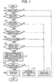
- Figure 1 illustrates a flowchart of stall and clutch excessive wear prevention control according to the present invention
- Figure 2 illustrates an engine drive power transmitting system of a vehicle to which the present invention is applied
- FIG 3 illustrates an automatic transmission employed in the system shown in Figure 2;
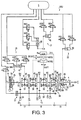
- FIG 4 illustrates an automatic clutch device employed in the system shown in Figure 2;
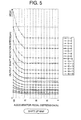
- Figure 5 illustrates a shift up map
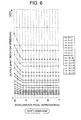
- Figure 6 illustrates a shift down map
- an automatic transmission 3 which is installed in a tractor-trailer with a diesel engine 1.
- the transmission 3 is coupled with the engine 1 via a clutch 2, and an output shaft 4 (Figure 3) of the transmission 3 is connected to a propeller shaft (not shown) to drive rear wheels (not shown).
- the engine 1 is electronically controlled by an engine control unit (ECU) 6.
- ECU 6 reads a current engine revolution speed and engine load from outputs of an engine rotation sensor 7 and accelerator opening sensor (accelerator pedal depression sensor) 8, and determines primarily from these outputs timing of fuel injection and an amount of fuel injection from a fuel injection pump la.
- a flywheel 1b is mounted on a crankshaft of the engine 1, and a ring gear 1c is formed along the periphery of the flywheel 1b.
- the sensor 7 outputs pulses.
- ECU 6 counts the number of the pulses per unit time to calculate the engine revolution speed.
- TMCU transmission control unit
- the clutch 2 is a mechanical friction clutch, and includes the flywheel 1b (input part of the clutch), a driven plate 2a (output part of the clutch), and a pressure plate 2b for frictionally contacting the driven plate 2a with the flywheel 1a and leaving the driven plate from the flywheel.
- the clutch 2 has a clutch booster 10 to cause the pressure plate 2b to move in an axial direction.
- the clutch 2 is generally disengaged and engaged in an automatic manner to lighten a driver's burden.
- a clutch stroke sensor 14 is provided for detecting a stroke of the clutch itself (i.e., position of the pressure plate 2b), and a clutch pedal stroke sensor 16 is provided for detecting how deep the clutch pedal 11 is stamped.
- the clutch booster 10 is connected to an air tank 5 via two air pipes “a” and “b” as indicated by the solid line, so that the clutch booster 10 is pneumatically activated by the air pressure supplied from the air tank 5.
- One of the air pipes “a” is used for automatic clutch disengagement and engagement
- the other air pipe “b” is used for manual clutch disengagement and engagement.
- the air pipe “a” is divided to two branch lines a1 and a2.
- On the second branch line a2 provided is an electromagnetic valve MVCE for emergency case.
- a double check valve DCV1 is provided at a position where these branch lines a1 and a2 meet.
- the air pipe “b” has a hydraulic valve 12 which is associated with the clutch booster 10.
- Another double check valve DCV2 is provided at a position where the air pipes "a" and "b" encounter.
- Each of the double check valves DCV1 and DCV2 is a three-way valve which is activated by differential pressure.
- the electromagnetic valves MVC1, MVC2 and MVCE are turned on and off under the control of TMCU 9. When turned on, the electromagnetic valve connects its upstream side to the downstream side. When turned off, the electromagnetic valve blocks up the air so that the upstream side is disconnected from the downstream side, and the downstream side is released to the atmosphere.
- the electromagnetic valve MVC1 is simply turned on and off in accordance with on and off of an ignition key. When the ignition key is in an off position, i.e., the vehicle is stopped, the electromagnetic valve MVC1 is turned off and interrupts the air pressure of the air tank 5.
- the electromagnetic valve MVC2 is a proportional control valve and able to arbitrarily control an amount (or flow rate) of air to be fed and discharged.
- the hydraulic pressure is fed from and returned to the master cylinder 13 upon stamping and releasing of the clutch pedal 11.
- the hydraulic pressure is fed to the hydraulic valve 12 via an oil line 13a as indicated by the broken line to open and close the hydraulic valve 12 and in turn to feed and release the air pressure to and from the clutch booster 10 for manual disengagement and engagement of the clutch 2.
- the air pressure passing therethrough causes the double check valve DCV2 to switch so that the air pressure reaches the clutch booster 10.
- the transmission 3 is a basically "always engaged" type of multi-stage transmission, and has sixteen forward gear positions and two backward gear positions.
- the transmission 3 has a splitter assembly 17 as an auxiliary transmission on its input side, a range gear assembly 19 as another auxiliary transmission on its output side, and a main gear assembly 18 between these two auxiliary gear assemblies.
- the transmission 3 transfers a drive power of the engine 1 from the input shaft 15 to the splitter 17, main gear assembly 18, range gear assembly 19 and output shaft 4 in this order.
- a gear shift unit GSU is provided for automatically shifting the transmission 3.
- GSU includes a splitter actuator 20, main actuator 21 and range actuator 22 for shifting the splitter assembly 17, main gear assembly 18 and range gear assembly 19 respectively.
- these actuators are also pneumatically driven under the control of TMCU 9.
- a current gear position of each of the gear assemblies 17, 18 and 19 is detected by an associated gear position switch 23 ( Figure 2).
- the rotation speed of the countershaft 32 is detected by a countershaft rotation sensor 26, and that of the output shaft 4 is detected by an output shaft rotation sensor 28.
- the automatic transmission described above also possesses a manual mode so that the transmission can be shifted up and down in response to a shift lever movement caused by the driver.
- a gear position change signal issued from a shift lever unit 29 located next to a driver' seat triggers disengagement and engagement of the clutch 2 and gear position change of the transmission 3.
- a shift switch installed in the shift lever unit 29 is turned on to output the gear position change signal to TMCU 9.
- TMCU 9 Upon receiving this signal, TMCU 9 selectively and/or cooperatively causes the clutch booster 10, splitter actuator 20, main gear actuator 21 and range gear actuator 22 to operate so as to perform a series of shift up (or down) operations (clutch disengagement, gear disengagement, gear engagement and clutch engagement). TMCU 9 also causes a monitor 31 to display a current gear position. Therefore, the shift switch incorporated in the shift lever unit 29 is a manual shift switch of the invention. This manual shift switch is turned on by the shift lever movement in this embodiment.
- the transmission In the automatic shift mode, if the shift lever 29a is in the D range, the transmission is automatically shifted up and down in accordance with the vehicle speed. It should be noted that even in the automatic shift mode, if the driver moves the shift lever 29a to UP or DOWN, the transmission is manually shifted.
- the automatic shift mode if the skip switch 25 is turned off (normal mode), the transmission gear position change takes place one gear at a time. This is advantageous when a tractor tows a trailer with a relatively heavy load.
- the skip switch 25 When the skip switch 25 is turned on (skip mode), the gear position change occurs every other gear (e.g., from first gear to third gear). This is advantageous when the tractor does not tow the trailer or tows the trailer with a relatively light load.
- the gear position change is effected completely according to the driver's intention.
- the shift lever 29a is in the D range, no gear position change takes place and a current gear position is maintained. Only when the driver operates the shift lever 29a to UP or DOWN, the transmission 3 is shifted up or down. If the skip switch 25 is turned off, the gear position change occurs one gear by one gear. If the skip switch 25 is turned on, the gear position change occurs every other gear. In this mode, the D range is an H (hold) range to keep a current gear position.
- An emergency shift switch 27 is also provided in the vicinity of the driver' seat. In case an electromagnetic valve of GSU fails, for instance, the driver presses an ON button and turns a knob to shift the transmission 3.
- the transmission 3 includes the input shaft 15, main shaft 33 and output shaft 4 that are arranged coaxially, and a countershaft 32 that extends below and in parallel to these shafts.
- the input shaft 15 is coupled to the driven plate 2a of the clutch 2.
- the input shaft 15 and main shaft 33 are supported such that they can rotate relative to each other.
- a split high gear SH is rotatably mounted on the input shaft 15.
- Main gears M4, M3, M2, M1 and MR are rotatably mounted on the main shaft 33 in this order from the front.
- These gears SH, M4, M3, M2 and M1 except for the gear MR always mesh with counter gears CH, C4, C3, C2 and C1 fixed on a counter shaft 32 respectively.
- the gear MR always meshes with an idle reverse gear IR, and the idle reverse gear IR always meshes with a counter gear CR secured on the counter shaft 32.
- the gears SH, M4,...mounted on the input shaft 15 and main shaft 33 have splines 36 for selection of themselves.
- first to fourth splines 37 to 40 fixed to the input shaft 15 and main shaft 33.
- First to fourth sleeves 42 to 45 always engage with the first to fourth splines 37 to 40 such that they can slide back and forth.
- a particular transmission gear is selected or the transmission is brought into a neutral condition (geared in and out). Movement of the first sleeve 42 is made by the splitter actuator 20, and those of the second to fourth sleeves 43 to 45 are made by the main actuator 21.
- the splitter assembly 17 and main gear assembly 18 have an "always-engaged" type structure that is automatically shifted up and down by the associated actuators 20 and 21.
- a spline portion of the splitter assembly 17 has an ordinary mechanical synchronization unit, but a spline portion of the main gear assembly 18 does not. Because of this, a so-called synchronization control is performed to match the engine revolution speed with the gear rotation speed so that the shifting can be made without the synchronization unit.
- the main gear assembly 18 but also the splitter gear assembly 17 have a neutral position so as to prevent rattle noise of gears.
- the detail of the neutral position of the splitter gear assembly can be found in Japanese Patent Application No. 11-319915 or corresponding European Patent Application No. 00 124 438.3 filed on November 8, 2000, entitled "MULTI-STAGE TRANSMISSION OF VEHICLE", the entire disclosures of which are incorporated herein by reference.
- the range gear assembly 19 has a planetary gear mechanism 34 and is shiftable to a high or low position.
- the planetary gear mechanism 34 includes a sun gear 65 secured on the rear end of the main shaft 33, a plurality of planetary gears 66 meshing with the outer periphery of the sun gear, and a ring gear 67 having inner teeth in mesh with the planetary gears 66.
- the planetary gears 66 are rotatably supported by a common carrier 68 that is connected to the output shaft 4.
- the ring gear 67 has a tubular portion 69 that is rotatably fit over the output shaft 4.
- the tubular portion 69 and the output shaft 4 constitute a double shaft structure.
- a fifth spline 41 extends from the tubular portion 69. Closely behind the fifth spline 41, provided is an output shaft spline 70 extending from the output shaft 4. In close front of the fifth spline 41, provided is a stationary spline 71 fixed to the transmission casing. A fifth sleeve 46 always meshes with the fifth spline 41 such that it can slide back and forth. Movement of the fifth sleeve 46 is controlled by the range gear actuator 22. Spline portions of the range gear assembly 19 have synchronization mechanisms.
- the fifth sleeve 46 moves backwards, it engages with the output shaft spline 70 so that the fifth spline 41 is coupled with the output shaft spline 70.
- the ring gear 67 and carrier 68 are fixed relative to each other, and the output shaft 4 is directly rotated at a reduction ratio of one. This is the high gear position.
- the transmission 3 has two gear positions (high and low gear positions) in the splitter assembly 17, four gear positions in the main gear assembly 18, and two gear positions (high and low) in the range gear assembly 19 when in the forward mode.
- the transmission 3 In the backward mode, the transmission 3 has two gear positions (high and low) upon switching of the splitter assembly 17.
- Each actuator includes one or more pneumatic cylinders activated by the air pressure from the air tank 5, and a plurality of electromagnetic valves for switching between application and releasing of the air pressure to and from the pneumatic cylinders.
- These electromagnetic valves are selectively operated by TMCU 9 so that the pneumatic cylinders are selectively activated.
- the splitter actuator 20 includes a pneumatic cylinder 47 and three electromagnetic valves MVH, MVF and MVG.
- the pneumatic cylinder 47 has a double piston.
- the main gear assembly actuator 21 includes a pneumatic cylinder 48 for gear selection, another pneumatic cylinder 49 for shifting, three electromagnetic valves MVC, MVD and MVE associated with the first pneumatic cylinder 48 and two electromagnetic valves MVB and MVA associated with the second pneumatic cylinder 49.
- the first pneumatic cylinder 48 has a double piston and the second pneumatic cylinder 49 has a single piston.
- the electromagnetic valve MVC When the electromagnetic valve MVC is turned off, the electromagnetic valve MVD is turned on and the electromagnetic valve MVE is turned off, the first pneumatic cylinder 48 is moved downwards in the drawing so that the third and fourth gears and N3 (neutral position between the third and fourth gears) of the main gear assembly can be selected.
- the electromagnetic valve MVC When the electromagnetic valve MVC is turned on, the electromagnetic valve MVD is turned off and the electromagnetic valve MVE is turned on, the first pneumatic cylinder 48 is moved into the neutral condition so that the first and second gears and N2 (neutral position between the first and second gears) of the main gear assembly can be selected.
- the electromagnetic valve MVC When the electromagnetic valve MVC is turned on, the electromagnetic valve MVD is turned off and the electromagnetic valve MVE is turned off, the first pneumatic cylinder 48 is moved upwards in the drawing so that the reverse gear and N1 of the main gear assembly are selectable.
- the second pneumatic cylinder 49 is brought into the neutral condition when the electromagnetic valve MVA is turned on and the electromagnetic valve MVB is turned on. This allows selection of N1, N2 and N3 of the main gear assembly.
- the pneumatic cylinder 49 is moved to the left in the drawing so that the second, fourth and reverse gears can be selected.
- the pneumatic cylinder 49 is moved to the right so that the first and third gears of the main gear assembly can be selected.
- the range gear actuator 21 includes a pneumatic cylinder 50 with a single piston, and two electromagnetic valves MVI and MVJ.
- the pneumatic cylinder 50 is moved to the right in the drawing when the electromagnetic valve MVI is turned on and the electromagnetic valve MVJ is turned off. This shifts the range gear assembly to the high gear position.
- the pneumatic cylinder 50 is moved to the left in the drawing when the electromagnetic valve MVI is turned off and the electromagnetic valve MVJ is turned on to shift the range gear assembly to the low gear position.
- the countershaft 32 is equipped with a countershaft brake 27.
- This brake 27 is a wet multiple plate type brake and actuated by the air pressure from the air tank 5.
- Application and non-application of the air pressure is switched by an electromagnetic valve MV BRK.
- the electromagnetic valve MV BRK When the electromagnetic valve MV BRK is turned on, the air pressure is applied to the countershaft brake 27 to apply a brake force to the counter shaft.
- the electromagnetic valve MV BRK is turned off, the air pressure is allowed to escape from the countershaft brake 27 so that no brake force acts on the countershaft.
- More detail of the counter shaft brake can be found in Japanese Patent Application No. 2000-83274 or corresponding European Patent Application No. ****** entitled "LUBRICATION SYSTEM FOR COUNTERSHAFT BRAKE" (Attorney Reference No. I 9100 EP, ISZ-EP-78), the entire disclosures of which are incorporated herein by reference.
- TMCU 9 has a shift up map as illustrated in Figure 5 and a shift down map as illustrated in Figure 6 in its memory.
- TMCU 9 conducts the automatic shifting according to these maps.
- a shift up curve from an n'th gear (n is an integer from one to fifteen) to an n+1'th gear is determined from an accelerator pedal depression (accelerator opening) (%) and output shaft rotation speed (rpm).
- rpm output shaft rotation speed
- a single point is determined from current accelerator depression and output shaft rotation speed. When the vehicle is accelerated, the rotation speed of the output shaft 4 connected to wheels gradually increases.
- the transmission is shifted up one gear by one gear every time a current point passes over a nearest shift up curve. If the skip mode is selected, the transmission is shifted up every other gear as a current point passes over a shift up curve above the nearest shift up curve.
- the shift down map of Figure 6 has a shift down curve from an n+1'th gear to an n'th gear, which is determined from the accelerator pedal depression (%) and output shaft rotation speed (rpm).
- a single point is defined from current accelerator pedal depression and output shaft rotation speed.
- the transmission is shifted down one gear at a time as a current point passes over a nearest shift down curve.
- the shifting down occurs every other gear.
- the driver can arbitrarily shift up and down the transmission independently of these maps.
- a single gear position change operation made by the driver causes the shifting by one gear.
- the shifting occurs by two gears upon a single gear position change operation.
- TMCU 9 calculates a current vehicle speed from the current output shaft rotation speed, and indicates it in a speedometer. In this manner, the vehicle speed is indirectly determined from the output shaft rotation speed. The output shaft rotation speed is proportional to the vehicle speed.
- the transmission is automatically shifted down to an appropriate gear position prior to clutch engagement regardless of the gear position change signal from the manual shift switch. In other words, even if the driver does not move the shift lever at all and maintains the current gear position, the appropriate gear position is automatically selected before the clutch is engaged.
- TMCU 9 determines at S101 whether the current mode is a manual mode from the output of the mode switch 24. If the manual mode has been selected, the program proceeds to S102. If not, the program advances to END. This is because stalling and excessive clutch slip upon acceleration after deceleration occur only in the manual mode. In the automatic mode, the transmission is automatically shifted down in accordance with the vehicle speed so that such problems would not occur. Whether the skip mode is selected or not is out of question as far as the engine stall and clutch excessive slip prevention is concerned.
- the program proceeds to S111.
- the current gear position is memorized as a target gear position for the next shifting. Thus, no shifting is effected.
- the program proceeds to S104.
- the engine idling rotation speed is 500 rpm, and the stall prevention control is performed when the input shaft rotation speed becomes smaller than the idling speed. This is because the clutch is surely disengaged in this situation.
- the clutch is disengaged during the deceleration when the input shaft rotation speed becomes about 900 rpm, for instance, which is slightly higher than the idling speed.
- the stall prevention control of the present invention is primarily applied when the clutch is disengaged near the idling rotation.
- the input shaft rotation speed is calculated from the countershaft rotation speed detected by the countershaft rotation speed sensor 26.
- TMCU 9 memorizes the numbers of teeth of the gears in the transmission and respective gear ratios, and obtains the input shaft rotation speed N1 from the equation shown below based on the countershaft rotation speed N2, the number of the teeth Z1 of the split high gear SH (input gear) and the number of the teeth Z2 of the counter gear CH (input counter gear).
- N1 (Z2/Z1) x N2
- TMCU 9 determines that the driver wants to accelerate the vehicle so that the clutch is automatically engaged. If the answer at S104 is yes, the program advances to S105. If no, the program advances to S111.
- a predetermined value e.g., 5%
- S105 it is determined whether the clutch is currently disengaged from the output of the clutch stroke sensor 14. This step is necessary because even if the clutch disengagement is assumed from the answer at S103, there is a possibility that the clutch is in actuality not disengaged due to interference with other control and/or malfunctioning and abnormality. It should be noted, however, that S105 is provided to just make sure that the clutch is indeed disengaged. If the clutch is not engaged at S105, the program proceeds to S106. Otherwise, the program proceeds to S111.
- the current gear position detected by the gear position switch 23 is compared with a predetermined start gear position (e.g., fourth or ninth gear) stored in TMCU 9. If the current gear is higher than the predetermined start gear, it means that the driver shifts down the transmission sufficiently during the deceleration by his or her own intent. In such case, the stall prevention control is not conducted. Therefore, the program proceeds to S111. If the current gear is greater than the predetermined gear, on the other hand, the program proceeds to S107.
- a predetermined start gear position e.g., fourth or ninth gear
- a most appropriate gear is selected in the shift up map shown in Figure 5 from the current accelerator pedal depression detected by the accelerator pedal sensor 8 and the current output shaft rotation speed detected by the output shaft rotation sensor 28.
- the selected most appropriate gear is compared with the preset start gear. If the former is smaller than the latter, the program proceeds to S109 to employ the preset start gear as the target gear. If the answer at S108 is no, the program goes to S110 to employ the selected most appropriate gear as the target gear. In this manner, the higher one is used as the target gear.
- the transmission After deciding the target gear, the transmission is automatically shifted to that target gear. Accordingly, appropriate shift down occurs. After that, the clutch is automatically engaged for subsequent acceleration of vehicle.
- the stall prevention control of the present invention when the driver stamps the accelerator pedal to raise the vehicle speed after deceleration, the transmission is first automatically shifted down to a gear position suited to the vehicle running condition and then the clutch is engaged. Therefore, the engine will not stall and the clutch will not slip excessively upon clutch engagement. This improves driver's comfort and protects the clutch.
- the higher one of the selected most appropriate gear and preset start gear is utilized as the target gear for subsequent acceleration of the vehicle since the transmission should be shifted to a gear not smaller than the preset start gear. For instance, if the vehicle is decelerated to a very slow speed while the high gear position is maintained, the transmission might be shifted down to a gear lower than the preset start gear (e.g., first or second gear) as far as the control is performed in accordance with the shift down map. If it happens, the driver experiences a shock upon clutch engagement and/or the engine revolution speed suddenly and steeply rises, which also makes the driver uncomfortable. In order to prevent such discomfort, a gear at least equal to the predetermined start gear is used in the present invention. If the vehicle is running at a certain speed when the driver intends to accelerate the vehicle, the preset start gear may be too low. In this case, the most appropriate gear selected from the map is utilized. Accordingly, the driver does not experience uncomfortable acceleration and clutch engagement.
- the preset start gear may be too low. In this case, the most
- the present invention is not limited to the illustrated and described embodiment.
- the most appropriate gear is not determined necessarily from the accelerator pedal depression and output shaft rotation speed.
- the vehicle speed may be employed instead of the output shaft rotation speed.
- the map used is not limited to the shift up map of Figure 5.
- the manual shift switch may be provided on or in a steering wheel.
- the transmission control unit 9 may be divided to three controllers such that a first controller automatically shifts the transmission 3 according to a gear position change signal issued from the manual shift switch 29a, a second controller automatically disengages the clutch 2 when automatic shifting takes place, and automatically engages the clutch 2 when accelerator pedal depression exceeds a predetermined value in a clutch disengaged condition, and a third controller decides a most appropriate gear in accordance with a current vehicle running condition, selects a higher one of the most appropriate gear and a predetermined start gear as a target gear, and shifts the transmission 3 to the target gear regardless of the gear position change signal from the manual shift switch 29a when the accelerator pedal depression 8 exceeds a prescribed amount in the clutch disengaged condition, and then engaging the clutch 2.
Claims (13)
- Automatikgetriebevorrichtung, enthaltend:eine erste Steuereinrichtung (9) zum automatischen Schalten eines Getriebes (3) gemäß einem Schaltpositionswechselsignal, das von einem manuell betätigten Gangschalter (29a) ausgegeben wird;eine zweite Steuereinrichtung (9) zum automatischen Ausrücken einer Kupplung (2) während des automatischen Schaltens und zum automatischen Einrücken der Kupplung (2), wenn der Umfang (8), in dem das Gaspedal niedergedrückt wird, bei ausgerückter Kupplung einen vorgegebenen Wert überschreitet; undeine dritte Steuereinrichtung (9), die entsprechend dem momentanen Fahrzustand des Kraftfahrzeugs entscheidet, welcher Gang am geeignetsten ist, und die sodann entweder den geeignetsten Gang oder einen vorbestimmten Start-Gang auswählt, je nachdem welcher dieser beiden Gänge der höhere ist, und die das Getriebe (3) unabhängig vom durch den manuell betätigten Gangschalter (29a) ausgegebenen Schaltpositionswechselsignal in den ausgewählten Gang schaltet, wenn der Umfang (8), in dem das Gaspedal niedergedrückt wird, bei ausgerückter Kupplung einen vorab festgelegten Wert überschreitet, und die die Kupplung (2) sodann einrückt.
- Automatikgetriebevorrichtung nach Anspruch 1, dadurch gekennzeichnet, dass der geeignetste Gang in einem Verzeichnis entsprechend dem gegenwärtigen Umfang (8), in dem das Gaspedal niedergedrückt wird, und der Drehzahl einer Ausgangswelle (4) des Getriebes (3) bestimmt wird.
- Automatikgetriebevorrichtung nach Anspruch 1 oder 2, dadurch gekennzeichnet, dass das Schaltpositionswechselsignal vom manuell betätigten Gangschalter (29a) in Abhängigkeit von einer Schalthebelbewegung ausgegeben wird.
- Automatikgetriebevorrichtung nach einem der Ansprüche 1 bis 3, dadurch gekennzeichnet, dass die Kupplung (2) ausgerückt wird, wenn die Drehzahl einer Eingangswelle (15) des Getriebes (3) unter einen Wert nahe der Motorleerlauf-Drehzahl fällt.
- Automatikgetriebevorrichtung nach Anspruch 4, dadurch gekennzeichnet, dass der Wert nahe der Motorleerlauf-Drehzahl 450 UpM beträgt.
- Automatikgetriebevorrichtung nach einem der vorhergehenden Ansprüche, dadurch gekennzeichnet, dass der vorbestimmte Wert 5 % des gesamten Gaspedal-Hubs beträgt.
- Automatikgetriebevorrichtung nach einem der vorhergehenden Ansprüche, dadurch gekennzeichnet, dass als Kupplung (2) eine mechanische Reibungskupplung dient.
- Verfahren, enthaltend die folgenden Schritte:A) automatisches Schalten eines Getriebes (3) gemäß einem von einem manuell betätigten Gangschalter (29a) ausgegebenen Schaltpositionswechselsignal;B) automatisches Ausrücken einer Kupplung (2) während des automatischen Umschaltens und automatisches Einrücken der Kupplung (2), wenn der Umfang (8), in dem das Gaspedal niedergedrückt wird, bei ausgerückter Kupplung einen bestimmten Wert übersteigt; undC) Bestimmung des geeignetsten Ganges entsprechend dem gegenwärtigen Fahrzustand des Kraftfahrzeugs, Auswahl entweder des geeignetsten Ganges oder eines vorher festgelegten Start-Ganges, je nachdem, bei welchem von beiden es sich um den höheren Gang handelt, und Schalten des Getriebes (3) in den ausgewählten Gang unabhängig vom durch den manuell betätigbaren Gangschalter (29a) gelieferten Schaltpositionswechselsignal, wenn der Umfang (8), in dem das Gaspedal niedergedrückt wird, bei ausgerückter Kupplung einen bestimmten Wert übersteigt, sowie nachfolgendes Einrücken der Kupplung (2).
- Verfahren nach Anspruch 8, dadurch gekennzeichnet, dass der geeignetste Gang in einer Übersicht gemäß dem Umfang (8), in dem das Gaspedal momentan niedergedrückt wird, und der Drehzahl einer Ausgangswelle (4) des Getriebes (3) bestimmt wird.
- Verfahren nach Anspruch 8 oder 9, dadurch gekennzeichnet, dass das Schaltpositionssignal von manuell betätigten Gangschalter (29a) in Abhängigkeit von einer Schalthebelbewegung ausgegeben wird.
- Verfahren nach Anspruch 8, 9 oder 10, dadurch gekennzeichnet, dass die Kupplung (2) ausgerückt wird, wenn die Drehzahl einer Eingangswelle (15) des Getriebes (3) unter einen Wert nahe der Motorleerlaufdrehzahl fällt.
- Verfahren nach Anspruch 11, dadurch gekennzeichnet, dass der Wert nahe der Motorleerlaufdrehzahl 450 UpM beträgt.
- Verfahren nach einem der Ansprüche 8 bis 12, dadurch gekennzeichnet, dass der vorbestimmte Wert 5 % des gesamten Gaspedal-Hubs beträgt.
Applications Claiming Priority (2)
| Application Number | Priority Date | Filing Date | Title |
|---|---|---|---|
| JP2000076370 | 2000-03-14 | ||
| JP2000076370A JP4092846B2 (ja) | 2000-03-14 | 2000-03-14 | 車両の変速装置 |
Publications (3)
| Publication Number | Publication Date |
|---|---|
| EP1134111A2 EP1134111A2 (de) | 2001-09-19 |
| EP1134111A3 EP1134111A3 (de) | 2002-06-19 |
| EP1134111B1 true EP1134111B1 (de) | 2004-07-28 |
Family
ID=18594127
Family Applications (1)
| Application Number | Title | Priority Date | Filing Date |
|---|---|---|---|
| EP01105507A Expired - Lifetime EP1134111B1 (de) | 2000-03-14 | 2001-03-05 | Steuerung für automatische Fahrzeuggetriebe |
Country Status (4)
| Country | Link |
|---|---|
| US (1) | US6415214B2 (de) |
| EP (1) | EP1134111B1 (de) |
| JP (1) | JP4092846B2 (de) |
| DE (1) | DE60104461T2 (de) |
Families Citing this family (18)
| Publication number | Priority date | Publication date | Assignee | Title |
|---|---|---|---|---|
| US6558293B2 (en) * | 2001-06-11 | 2003-05-06 | General Motors Corporation | Garage shift control for a motor vehicle automatic transmission |
| DE10334930A1 (de) * | 2003-07-31 | 2005-02-24 | Zf Friedrichshafen Ag | Verfahren zum Betreiben eines Kraftfahrzeugautomatgetriebes |
| US6935204B2 (en) | 2003-10-31 | 2005-08-30 | Caterpillar Inc | Automated manual transmission and shift method |
| JP5137375B2 (ja) * | 2006-09-29 | 2013-02-06 | 本田技研工業株式会社 | 動力伝達装置の制御方法 |
| JP4306713B2 (ja) * | 2006-10-20 | 2009-08-05 | トヨタ自動車株式会社 | 車両の制御装置、制御方法、その制御方法をコンピュータで実現するプログラムおよびそのプログラムを記録した記録媒体 |
| DE102007010295B4 (de) | 2007-03-02 | 2020-09-03 | Zf Friedrichshafen Ag | Verfahren zur Steuerung eines Antriebsstrangs eines Kraftfahrzeugs |
| DE102007012875A1 (de) * | 2007-03-17 | 2008-09-18 | Zf Friedrichshafen Ag | Verfahren zum Betreiben eines Automatgetriebes |
| DE102007024363A1 (de) * | 2007-05-24 | 2008-11-27 | Zf Friedrichshafen Ag | Verfahren zur Steuerung eines Antriebsstrangs eines Kraftfahrzeugs |
| JP5251484B2 (ja) * | 2008-12-19 | 2013-07-31 | 日産自動車株式会社 | ハイブリッド車両の制御装置 |
| JP5620671B2 (ja) * | 2009-11-24 | 2014-11-05 | ヤマハ発動機株式会社 | 変速装置 |
| SE534650C2 (sv) * | 2010-02-01 | 2011-11-08 | Scania Cv Ab | Förfarande och system för styrning av en växellåda |
| EP2397921B1 (de) * | 2010-06-17 | 2017-08-30 | Blancpain S.A. | Mechanismus für springendes Karussell-Gestell |
| EP2791554B1 (de) * | 2011-12-15 | 2021-05-05 | Volvo Lastvagnar Ab | Steuerverfahren für ein automatikgetriebe eines kraftfahrzeuges, system zur steuerung eines solchen getriebes und kraftfahrzeug mit einem solchen system |
| DE102013214241A1 (de) * | 2013-07-22 | 2015-01-22 | Bayerische Motoren Werke Aktiengesellschaft | Vorrichtung zur Optimierung der Gangwechselsteuerung für ein Automatikgetriebe in einem Kraftfahrzeug |
| DE102013013154A1 (de) * | 2013-08-08 | 2015-02-12 | Frank Ropertz | Doppelkupplungsgetriebe |
| JP5702840B2 (ja) * | 2013-09-09 | 2015-04-15 | ヤマハ発動機株式会社 | 変速装置 |
| JP2016005929A (ja) * | 2014-06-20 | 2016-01-14 | トヨタ自動車株式会社 | 車両の制御装置 |
| DE102014019127B4 (de) * | 2014-12-19 | 2016-11-03 | Audi Ag | Verfahren zum Betreiben einer Getriebeeinrichtung für ein Kraftfahrzeug sowie entsprechende Getriebeeinrichtung |
Family Cites Families (6)
| Publication number | Priority date | Publication date | Assignee | Title |
|---|---|---|---|---|
| US5157608A (en) * | 1990-09-14 | 1992-10-20 | Ford Motor Company | Electronic control system for multiple ratio transmission including circuit pressure control |
| JP3129126B2 (ja) * | 1994-12-09 | 2001-01-29 | 三菱自動車工業株式会社 | 電気自動車の変速制御方法 |
| JPH0988651A (ja) * | 1995-09-29 | 1997-03-31 | Toyota Motor Corp | エンジンブレーキ力制御装置 |
| US5984828A (en) * | 1998-03-16 | 1999-11-16 | Meritor Heavy Vehicle Systems, Llc | Control methods for a shift by wire vehicle transmission |
| JP3297999B2 (ja) | 1998-05-12 | 2002-07-02 | 住友金属工業株式会社 | マンドレルミル圧延設備およびそれに用いる圧延方法 |
| DE19921920B4 (de) * | 1999-05-12 | 2005-11-17 | Zf Sachs Ag | Verfahren zum Schützen einer Reibungskupplung |
-
2000
- 2000-03-14 JP JP2000076370A patent/JP4092846B2/ja not_active Expired - Fee Related
-
2001
- 2001-03-05 EP EP01105507A patent/EP1134111B1/de not_active Expired - Lifetime
- 2001-03-05 DE DE60104461T patent/DE60104461T2/de not_active Expired - Lifetime
- 2001-03-08 US US09/802,042 patent/US6415214B2/en not_active Expired - Fee Related
Also Published As
| Publication number | Publication date |
|---|---|
| DE60104461D1 (de) | 2004-09-02 |
| JP2001260714A (ja) | 2001-09-26 |
| US20010023385A1 (en) | 2001-09-20 |
| EP1134111A3 (de) | 2002-06-19 |
| JP4092846B2 (ja) | 2008-05-28 |
| DE60104461T2 (de) | 2005-08-18 |
| US6415214B2 (en) | 2002-07-02 |
| EP1134111A2 (de) | 2001-09-19 |
Similar Documents
| Publication | Publication Date | Title |
|---|---|---|
| EP1134111B1 (de) | Steuerung für automatische Fahrzeuggetriebe | |
| EP1136308B1 (de) | Anordnung zum gezielten Ansteuern von einer Kupplung | |
| EP1130292B1 (de) | System und Methode zur Verhinderung von Motorhöchstdrehzahlen für Automatik-Getriebe von Kraftfahrzeugen | |
| US6383116B1 (en) | Transmission system | |
| EP1146258A1 (de) | Automatisches Getriebe für Kraftfahrzeuge | |
| JP4515592B2 (ja) | 車両の自動変速装置 | |
| JP4100057B2 (ja) | 変速制御装置 | |
| JP4343415B2 (ja) | 車両の自動変速装置 | |
| JP4415291B2 (ja) | 車両の自動変速装置 | |
| JP3893842B2 (ja) | 車両のオートクラッチ制御装置 | |
| JP3797220B2 (ja) | 車両の自動変速装置 | |
| JP4470272B2 (ja) | 車両の自動変速装置 | |
| JP4078783B2 (ja) | 車両の自動クラッチ装置 | |
| JP4221957B2 (ja) | 変速制御装置 | |
| JP4637996B2 (ja) | 車両の自動変速装置 | |
| JP2004138143A (ja) | トランスミッション制御装置 | |
| JP4470919B2 (ja) | 車両のオートクラッチ制御装置 | |
| JP3888153B2 (ja) | 車両の坂道発進補助装置 | |
| JP2004197772A (ja) | トランスミッション制御装置 | |
| JP4284825B2 (ja) | 車両の自動変速装置 | |
| JP2003185005A (ja) | 自動変速装置 | |
| JP4239359B2 (ja) | 車両の自動変速装置 | |
| JP2004060837A (ja) | 変速制御装置 |
Legal Events
| Date | Code | Title | Description |
|---|---|---|---|
| PUAI | Public reference made under article 153(3) epc to a published international application that has entered the european phase |
Free format text: ORIGINAL CODE: 0009012 |
|
| AK | Designated contracting states |
Kind code of ref document: A2 Designated state(s): AT BE CH CY DE DK ES FI FR GB GR IE IT LI LU MC NL PT SE TR |
|
| AX | Request for extension of the european patent |
Free format text: AL;LT;LV;MK;RO;SI |
|
| PUAL | Search report despatched |
Free format text: ORIGINAL CODE: 0009013 |
|
| AK | Designated contracting states |
Kind code of ref document: A3 Designated state(s): AT BE CH CY DE DK ES FI FR GB GR IE IT LI LU MC NL PT SE TR |
|
| AX | Request for extension of the european patent |
Free format text: AL;LT;LV;MK;RO;SI |
|
| 17P | Request for examination filed |
Effective date: 20021126 |
|
| AKX | Designation fees paid |
Designated state(s): DE FR GB |
|
| 17Q | First examination report despatched |
Effective date: 20030822 |
|
| GRAP | Despatch of communication of intention to grant a patent |
Free format text: ORIGINAL CODE: EPIDOSNIGR1 |
|
| GRAS | Grant fee paid |
Free format text: ORIGINAL CODE: EPIDOSNIGR3 |
|
| GRAA | (expected) grant |
Free format text: ORIGINAL CODE: 0009210 |
|
| AK | Designated contracting states |
Kind code of ref document: B1 Designated state(s): DE FR GB |
|
| REG | Reference to a national code |
Ref country code: GB Ref legal event code: FG4D |
|
| REG | Reference to a national code |
Ref country code: IE Ref legal event code: FG4D |
|
| REF | Corresponds to: |
Ref document number: 60104461 Country of ref document: DE Date of ref document: 20040902 Kind code of ref document: P |
|
| ET | Fr: translation filed | ||
| PLBE | No opposition filed within time limit |
Free format text: ORIGINAL CODE: 0009261 |
|
| STAA | Information on the status of an ep patent application or granted ep patent |
Free format text: STATUS: NO OPPOSITION FILED WITHIN TIME LIMIT |
|
| 26N | No opposition filed |
Effective date: 20050429 |
|
| PGFP | Annual fee paid to national office [announced via postgrant information from national office to epo] |
Ref country code: DE Payment date: 20130731 Year of fee payment: 13 |
|
| PGFP | Annual fee paid to national office [announced via postgrant information from national office to epo] |
Ref country code: GB Payment date: 20130729 Year of fee payment: 13 Ref country code: FR Payment date: 20130808 Year of fee payment: 13 |
|
| REG | Reference to a national code |
Ref country code: DE Ref legal event code: R119 Ref document number: 60104461 Country of ref document: DE |
|
| REG | Reference to a national code |
Ref country code: DE Ref legal event code: R079 Ref document number: 60104461 Country of ref document: DE Free format text: PREVIOUS MAIN CLASS: B60K0041220000 Ipc: F16H0061020000 |
|
| GBPC | Gb: european patent ceased through non-payment of renewal fee |
Effective date: 20140305 |
|
| REG | Reference to a national code |
Ref country code: DE Ref legal event code: R119 Ref document number: 60104461 Country of ref document: DE Effective date: 20141001 Ref country code: DE Ref legal event code: R079 Ref document number: 60104461 Country of ref document: DE Free format text: PREVIOUS MAIN CLASS: B60K0041220000 Ipc: F16H0061020000 Effective date: 20141119 |
|
| REG | Reference to a national code |
Ref country code: FR Ref legal event code: ST Effective date: 20141128 |
|
| PG25 | Lapsed in a contracting state [announced via postgrant information from national office to epo] |
Ref country code: FR Free format text: LAPSE BECAUSE OF NON-PAYMENT OF DUE FEES Effective date: 20140331 Ref country code: GB Free format text: LAPSE BECAUSE OF NON-PAYMENT OF DUE FEES Effective date: 20140305 Ref country code: DE Free format text: LAPSE BECAUSE OF NON-PAYMENT OF DUE FEES Effective date: 20141001 |