EP1223044A2 - Drucksystem - Google Patents
Drucksystem Download PDFInfo
- Publication number
- EP1223044A2 EP1223044A2 EP02000698A EP02000698A EP1223044A2 EP 1223044 A2 EP1223044 A2 EP 1223044A2 EP 02000698 A EP02000698 A EP 02000698A EP 02000698 A EP02000698 A EP 02000698A EP 1223044 A2 EP1223044 A2 EP 1223044A2
- Authority
- EP
- European Patent Office
- Prior art keywords
- print data
- size
- printing
- stocker
- Prior art date
- Legal status (The legal status is an assumption and is not a legal conclusion. Google has not performed a legal analysis and makes no representation as to the accuracy of the status listed.)
- Granted
Links
Images


Classifications
-
- B—PERFORMING OPERATIONS; TRANSPORTING
- B41—PRINTING; LINING MACHINES; TYPEWRITERS; STAMPS
- B41J—TYPEWRITERS; SELECTIVE PRINTING MECHANISMS, i.e. MECHANISMS PRINTING OTHERWISE THAN FROM A FORME; CORRECTION OF TYPOGRAPHICAL ERRORS
- B41J13/00—Devices or arrangements of selective printing mechanisms, e.g. ink-jet printers or thermal printers, specially adapted for supporting or handling copy material in short lengths, e.g. sheets
- B41J13/0009—Devices or arrangements of selective printing mechanisms, e.g. ink-jet printers or thermal printers, specially adapted for supporting or handling copy material in short lengths, e.g. sheets control of the transport of the copy material
- B41J13/0027—Devices or arrangements of selective printing mechanisms, e.g. ink-jet printers or thermal printers, specially adapted for supporting or handling copy material in short lengths, e.g. sheets control of the transport of the copy material in the printing section of automatic paper handling systems
-
- B—PERFORMING OPERATIONS; TRANSPORTING
- B41—PRINTING; LINING MACHINES; TYPEWRITERS; STAMPS
- B41J—TYPEWRITERS; SELECTIVE PRINTING MECHANISMS, i.e. MECHANISMS PRINTING OTHERWISE THAN FROM A FORME; CORRECTION OF TYPOGRAPHICAL ERRORS
- B41J13/00—Devices or arrangements of selective printing mechanisms, e.g. ink-jet printers or thermal printers, specially adapted for supporting or handling copy material in short lengths, e.g. sheets
- B41J13/0009—Devices or arrangements of selective printing mechanisms, e.g. ink-jet printers or thermal printers, specially adapted for supporting or handling copy material in short lengths, e.g. sheets control of the transport of the copy material
- B41J13/0036—Devices or arrangements of selective printing mechanisms, e.g. ink-jet printers or thermal printers, specially adapted for supporting or handling copy material in short lengths, e.g. sheets control of the transport of the copy material in the output section of automatic paper handling systems
Definitions
- the present invention relates to a printing system for direct printing using digital data.
- printed sheets are ejected into a stocker attached to the printing press and then transported for post-processing such as a bookbinding process.
- the printing press is capable of printing on sheets of paper having a variety of sizes.
- the stocker receives an accumulation of printed sheets of difference sizes, for example, by the ejection of a large number of A4 printed sheets followed by a large number of A3 printed sheets, a sheet stack falling apart accident is liable to occur in the stocker.
- the present invention is intended for a printing system for continuously printing products of different sheet sizes.
- the printing system comprises: a) a printing apparatus including a-1) a printing section for continuously printing a plurality of print data on a plurality of sheets of paper to provide a plurality of printed sheets, a-2) a stock section including at least one stocker, and a-3) an ejecting mechanism for ejecting the plurality of printed sheets into the stock section; and b) a controller including b-1) an acquiring element for acquiring print sizes corresponding respectively to the plurality of print data, b-2) a comparing element for making a comparison between the print sizes, and b-3) a control element for controlling the printing section and the ejecting mechanism based on a result of the comparison by the comparing element to provide a stable stack including printed sheets of different sheet sizes in the stock section.
- the print sizes of the print data to be continuously printed are compared with each other. If the print size of print data to be printed later is greater by at least a predetermined value than the print size of printed sheets stored in the stocker, a printing process is suspended, and an operator is prompted to remove the printed sheets out of the stocker; otherwise the destination of the printed sheets for the print data to be printed later is changed to another stocker capable of storing the printed sheets.
- the controller comprises: a sorting element for sorting the print sizes of the plurality of print data to determine printing order, based on the result of the comparison between the print sizes by the comparing element; and an element for controlling the printing section to print the plurality of print data in the printing order.
- Fig. 1 shows an overview of a first printing system 100 according to the present invention.
- the printing system 100 comprises a controller 1, a digital printing press 2, and image processing terminals 4.
- the controller 1 and the image processing terminals 4 are connected through a network 3.
- the controller 1 and the digital printing press 2 are connected through a communication line CL.
- the image processing terminals 4 produce page data PD for printing a product comprised of a plurality of pages or book data BD comprised of a plurality of page data PD.
- the controller 1 receives the page data PD or book data BD produced by the image processing terminals 4 through the network 3.
- the controller 1 rasterizes the received page data PD or book data BD, and transmits resultant print data RPD representing a print image to the digital printing press 2 connected thereto through the communication line CL.
- the digital printing press 2 performs printing under the control of the controller 1.
- the digital printing press 2 comprises a control section 21, a stocker 22, and a detector 23 in addition to a paper feed section, a transport path and a printing section which are not shown.
- the control section 21 controls the entire digital printing press 2.
- the print data RPD transmitted from the controller 1 through the communication line CL is received by the control section 21 and is converted into binary half-tone data which in turn is transmitted to the printing section.
- the printing section transfers a print image represented in a half-tone form onto the sheet.
- a printed sheet 24 is transported through the transport path and stored in the stocker 22.
- a control signal CD transmitted through the communication line CL is similarly received by the control section 21 and used to control the sections of the digital printing press 2.
- the control section 21 transmits a status signal SD through the communication line CL to inform the controller 1 about the status of the digital printing press 2.
- the stocker 22 is provided to store the sheets 24 of paper printed in the printing section not shown.
- the stocker 22 has a stocker floor painted black for judgment by the detector 23 to be described later.
- the stocker 22 is provided with the detector 23.
- the detector 23 has a light emitter 231 and a light receiver 232. Light emitted from the light emitter 231 is reflected from the stocker floor of the stocker 22 or from the printed sheets 24. Since the stocker floor is black, there is a difference in illuminance between the light reflected when the printed sheets 24 are accumulated in the stocker 22 and the light reflected when they are not.
- the detector 23 detects a change in illuminance of the reflected light received by the light receiver 232 to detect the presence/absence of the printed sheets 24 in the stocker 22.
- the detector 23 transmits information about the presence/absence of the printed sheets 24 through a signal line 25 to the control section 21.
- the detector 23 transmits "1" to the control section 21 when the printed sheets 24 are accumulated in the stocker 22, and "0" when they are not.
- the control section 21 adds the information about the presence/absence of the printed sheets 24 to the status signal SD to be transmitted through the communication line CL to inform the controller 1 about the presence/absence of the printed sheets 24 in the stocker 22.
- the technique of detecting the printed sheets 24 in the stocker 22 by the detector 23 is not limited to the above-mentioned example.
- a detector for transmission-type detection, rather than the above-mentioned reflection-type detection, may be provided.
- the printed sheets 24 are products resulting from the repeated operations of the control section 21, the paper feed section not shown, the transport path not shown and the printing section not shown to print the print image represented by the print data RPD on a plurality of sheets of paper.
- the printed sheets 24 include printed sheets 24a of "A4" size when the size of the print image represented by the print data RPD is "A4,” and printed sheets 24b of "A3" size when the size of the print image is "A3.”
- the printed sheets 24 include the printed sheets 24a of "A4" size when the print size in the setting of the page data PD is "A4,” and the printed sheets 24b of "A3" size when the print size in the setting of the page data PD is "A3.”
- slip paper is inserted between the printed sheets 24a and 24b or the printed sheets 24a and 24b are shifted in position when stored.
- the signal line 25 is used to transmit the information about whether or not the printed sheets 24 are stored in the stocker 22 from the detector 23 to the control section 21.
- Fig. 2 shows a construction of the controller 1.
- the controller 1 is a personal computer in typical use, and comprises a CPU 11, a display 12, an input section 13, a network I/F 14, a media drive 15, a storage section 16, a memory 17 and the communication line CL.
- the CPU 11 controls the entire controller 1, and in particular executes in the memory 17 a program recorded on a media disc 18 inserted in the media drive 15 to implement the functions of the controller 1.
- the display 12 presents thereon information necessary for the operations of the controller 1.
- the input section 13 includes a mouse and a keyboard, and is used by an operator entering a command into the controller 1.
- the network I/F 14 is provided to connect the controller 1 and the network 3 to each other.
- the controller 1 receives the page data PD or book data BD from the image processing terminals 4 connected to the network 3.
- a program for implementing the functions of the controller 1 may be downloaded from a server not shown through the network I/F 14.
- the controller 1 transmits the print data RPD and the control signal CD to the digital printing press 2 through the network I/F 14 and receives the status signal SD from the digital printing press 2 through the network I/F 14.
- the media drive 15 is used to read the program recorded on the media disc 18. The program read by the media drive 15 implements the functions of the controller 1.
- a subsequent process may be performed by recording the page data PD or book data BD produced by the image processing terminals 4 on the media disc 18 and reading the media disc 18 by the media drive 15.
- the storage section 16 stores therein the program read by the media drive 15.
- the storage section 16 also stores therein the page data PD, the book data BD and print data RPD.
- the communication line CL is connected to the digital printing press 2 and is particularly used to transmit the print data RPD and the control signal CD to the control section 21 and to receive the status signal SD transmitted from the digital printing press 2.
- the memory 17 is a work area in which the CPU 11 executes the program stored by the storage section 16. In consequence of the execution of the program by the CPU 11, the functions of a print size acquiring section 171, a print size comparing section 172, and a printing control section 173 are implemented in the memory 17.
- the print size acquiring section 171 acquires and stores print sizes of at least two print data RPD, respectively.
- the print size acquiring section 171 comprises a print image size acquiring section 1711 and a page size acquiring section 1712.
- the print image size acquiring section 1711 acquires the size of the print image represented by the print data RPD produced by rasterizing the page data PD produced by the image processing terminals 4 in an RIP section (not shown) of the controller 1.
- the print image size acquiring section 1711 acquires dimensions measured respectively in the X- and Y-directions (referred to hereinafter as x- and y-dimensions) of an area occupied by the print image represented by the print data RPD.
- the page size acquiring section 1712 acquires a page size designated by the page data PD or book data BD produced by the image processing terminals 4.
- a sheet size on which the page data PD or book data BD is to be printed information about the sheet size is contained in the page data PD or book data BD.
- the page size acquiring section 1712 acquires the sheet size information contained in the page data PD or book data BD thus designated.
- the print size acquiring section 171 uses the functions of the print image size acquiring section 1711 and/or the page size acquiring section 1712 to acquire a print size (referred to hereinafter as a first print size SF) of print data printed first (referred to hereinafter as first print data RPDF) and a print size (referred to hereinafter as a second print size SB) of print data to be printed next (referred to hereinafter as second print data RPDB), and stores the first and second print sizes SF and SB.
- a print size referred to hereinafter as a first print size SF
- first print data RPDF print data printed first
- second print size SB print size of print data to be printed next
- the print size comparing section 172 makes a comparison between the first print size SF and the second print size SB both acquired by the print size acquiring section 171.
- the printing control section 173 determines whether to continuously operate the digital printing press 2 or not, based on a result of comparison between the print sizes SF and SB.
- the printing control section 173 determines whether to do printing of the second print data RPDB continuously after the printing of the first print data RPDF or not, thereby to determine whether to continuously operate the digital printing press 2 or not. Additionally, the printing control section 173 prompts an operator of the controller 1 to determine whether to continuously operate the digital printing press 2 or not.
- the printing control section 173 For determining whether to continuously operate the digital printing press 2 or not, the printing control section 173 first references the presence/absence of the accumulation of the printed sheets 24 in the stocker 22 which is detected by the detector 23 of the digital printing press 2. If the printed sheets 24 are not accumulated in the stocker 22, there is no possibility that a stack of the printed sheets 24 falls apart. Then, the controller 1 need not effect particular control of the continuous operation of the digital printing press 2. Only when informed about the presence of the accumulation of the printed sheets 24 in the stocker 22 from the detector 23, the controller 1 operates the print size acquiring section 171, the print size comparing section 172 and the printing control section 173 to control the continuous operation of the digital printing press 2.
- the printing control section 173 comprises a permissible limit table 1731.
- the permissible limit table 1731 contains a plurality of permissible limits of differences resulting from the comparison between the first print size SF and the second print size SB.
- the falling apart of a stack of the printed sheets 24 of different sheet sizes in the stocker 22 does not occur (i.e., a stable stack of the printed sheets 24 are provided) when the difference, if any, obtained by the comparison between the first print size SF and the second print size SB in the print size comparing section 172 is not significant.
- This allows the digital printing press 2 to do printing of the second print data RPDB continuously after the first print data RPDF.
- the printing control section 173 references one of the permissible limits contained in the permissible limit table 1731, and determines to print the second print data RPDB continuously after the first print data RPDF if the difference between the first print size SF and the second print size SB obtained as a result of comparison by the print size comparing section 172 falls within the referenced permissible limit.
- Fig. 3 shows an example of the construction of the permissible limit table 1731.
- the permissible limit table 1731 may contain any numerical value entered by the operator of the controller 1.
- the controller 1 has the functions of:
- Fig. 4 is a flowchart for illustrating the operation of the printing system 100 and, more particularly, the operations of the controller 1 and the digital printing press 2.
- Step S1 the controller 1 receives and rasterizes the page data PD or book data BD produced by the image processing terminals 4 to produce the print data RPD, and the digital printing press 2 performs printing.
- the print data RPD for use in printing in Step S1 is used for the first printing in the printing system 100 and thus is defined as the first print data RPDF.
- the print size acquiring section 171 causes the print image size acquiring section 1711 or the page size acquiring section 1712 to function to acquire the first print size SF from the first print data RPDF. It is assumed in this case that the print size acquiring section 171 causes the print image size acquiring section 1711 to acquire the x- and y-dimensions of the area occupied by the print image represented by the first print data RPDF as the first print size SF to store the first print size SF.
- the page size acquiring section 1712 analyzes the page data PD or book data BD before the rasterization into the first print data RPDF to retrieve a description about a page size contained therein.
- the print size acquiring section 171 may cause the page size acquiring section 1712 to acquire and store the description about the retrieved page size as the first print size SF.
- Step S3 a judgment is made as to whether or not the controller 1 has received new page data PD or book data BD from the image processing terminals 4. If the controller 1 has not received the new data, the processing is terminated.
- the controller 1 rasterizes the received page data PD or book data BD to produce the print data RPD.
- the print data RPD for use in printing in the processes of Step S3 and its subsequent steps is to be printed after the first print data RPDF printed first in Step S1 and thus is defined as the second print data RPDB.
- Step S4 the controller 1 verifies whether or not the printed sheets 24 are accumulated in the stocker 22 of the digital printing press 2.
- the printing control section 173 of the controller 1 transmits the control signal CD through the communication line CL to the control section 21 of the digital printing press 2.
- the control section 21 of the digital printing press 2 receives a signal through the signal line 25 from the detector 23 in response to the control signal CD.
- the control section 21 judges that the printed sheets 24 are accumulated in the stocker 22 if the signal from the detector 23 is "1" and that the printed sheets 24 are not accumulated in the stocker 22 if the signal from the detector 23 is "0.”
- the control section 21 adds this information to the status signal SD to transmit the status of the stocker 22 to the controller 1.
- Step S5 the print size acquiring section 171 resets the first print size SF acquired in Step S2 to "0." Since the printed sheets 24 are not accumulated in the stocker 22, printing using the second print data RPDB produced in Step S3 becomes the substantially first printing. After the completion of the process in Step S5, the process proceeds to Step S12 to perform printing of the second print data RPDB.
- Step S6 the print size acquiring section 171 causes the print image size acquiring section 1711 or the page size acquiring section 1712 to function to acquire the second print size SB from the second print data RPDB.
- the print size acquiring section 171 causes the print image size acquiring section 1711 to acquire the x- and y-dimensions of the area occupied by the print image represented by the second print data RPDB as the second print size SB to store the second print size SB.
- the page size acquiring section 1712 analyzes the page data PD or book data BD before the rasterization into the second print data RPDB to retrieve a description about a page size contained therein.
- the print size acquiring section 171 may cause the page size acquiring section 1712 to acquire and store the description about the retrieved page size as the second print size SB.
- Step S7 the printing control section 173 reads a permissible limit C from the permissible limit table 1731.
- the operator of the controller 1 selects the permissible limit C to be referenced for comparison between the first print size SF and the second print size SB among the plurality of permissible limits contained in the permissible limit table 1731 in consideration for such as the type and strength of the sheets used in the digital printing press 2.
- the permissible limit C includes a permissible x-dimension limit Cx and a permissible y-dimension limit Cy.
- Steps S8 and S9 are the process steps of making a comparison between the first print size SF and the second print size SB.
- Step S8 a comparison is made between the x-dimension SFx of the first print size SF and the x-dimension SBx of the second print size SB. This comparison is made using Expressions (1) and (2). SFx - (SBx + Cx) ⁇ 0
- Expression (1) is to compare the first print size SF with the sum of the second print size SB and the permissible x-dimension limit Cx. If Expression (1) holds, the x-dimension of the first print size SF is sufficiently greater than the x-dimension of the second print size SB, and the process then proceeds to a judgment in Step S9.
- Expression (2) is to judge whether the difference between the x-dimensions of the first and second print sizes SF and SB falls within the permissible x-dimension limit Cx. If Expression (2) holds even when the second print size SB is greater than the first print size SF, it is judged that there is no possibility that the stack falling apart, and the process proceeds to the judgment in Step S9. If Expression (2) does not hold, it is judged that there is a possibility that the stack falls apart, and the process proceeds to Step S10.
- Expression (1) and (2) may be used for comparison between the x-dimension of the first print size SF and the x-dimension of the second print size SB.
- Step S9 a comparison is made between the y-dimension SFy of the first print size SF and the y-dimension SBy of the second print size SB.
- This comparison between the first print size SF and the second print size SB is made using Expressions (3) and (4).
- Expressions (3) and (4) differ from Expressions (1) and (2) only in the direction of the dimension to be compared. Thus, if there is no possibility that the stack falls apart as a result of the comparison in Expressions (3) and (4), the process proceeds to Step S12; otherwise the process proceeds to Step S10.
- Expression (3) and (4) may be used for comparison between the y-dimension of the first print size SF and the y-dimension of the second print size SB.
- Step S10 the printing control section 173 shows on the display 12 a message such as "Remove accumulated printed sheets out of the stocker of the printing press" to prompt the operator of the controller 1 to remove the accumulated printed sheets 24 out of the stocker 22 of the digital printing press 2.
- the printing control section 173 verifies the status of the stocker 22 through the control section 21 of the digital printing press 2 (Step S11). As far as the printed sheets 24 remain in the stocker 22, the printing process is not performed on the second print data RPDB, and the process returns to Step S10 since there is a possibility that the stack falls apart. Thus, since the printing process is not performed on the second print data RPDB as far as the printed sheets 24 remain in the stocker 22, the stack falling apart does not occur. The time for the operator of the controller I to remove the printed sheets 24 is ensured.
- Step S11 If it is judged in Step S11 that the printed sheets 24 are absent in the stocker 22, the printing control section 173 stops showing the message on the display 12, and the process goes to Step S5. Then, the print size acquiring section 171 sets the stored first print size SF to "0." After the removal of the printed sheets 24 out of the stocker 22, the printed sheets 24 to be produced by the next printing process on the second print data RPDB become the first printed sheets 24 in the stocker 22. This means the absence of the first print size SF.
- Step S12 the controller 1 effects the printing of the second print data RPDB.
- the CPU 11 of the controller 1 transmits the second print data RPDB through the communication line CL to the digital printing press 2, and the control section 21 of the digital printing press 2 causes the paper feed section, transport path and printing section not shown to function to perform the printing of the second print data RPDB.
- Step S13 After the completion of the printing of the second print data RPDB, the second print size SB is substituted for the first print size SF stored in the print size acquiring section 171 (Step S13). This is because after the accumulation of the printed sheets 24 in the stocker 22 due to the printing process of the second print data RPDB in the process of Step S12, the print size of these printed sheets 24 is handled as the first print size SF for the next printing process. After the completion of the process in Step S13, the process returns to Step S3. Thus, the printing process in the printing system 100 is repeatedly performed.
- Figs. 5A through 5D specifically illustrate the operation of the printing system 100 in the flowchart of Fig. 4. It is assumed that the sizes of the sheets usable in the digital printing press 2 in the printing system 100 of Fig. 1 include “A3w,” “A3” and “A4.” The "A3w” sheet has x- and y-dimensions slightly greater than those of the "A3" sheet.
- Fig. 5B shows a status in the printing system 100 when printing based on print data RPD2 is performed following the first printing. It is assumed that the area occupied by a print image represented by the print data RPD2 has the "A3" size.
- the controller 1 defines the print data RPD1 as the first print data RPDF and the print data RPD2 as the second print data RPDB to execute the processes of Step S3 and its subsequent steps shown in the flowchart of Fig. 4.
- both of the limits Cx and Cy in the permissible limit C are set at "0.”
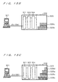
- Fig. 5C shows a status in the printing system 100 when printing based on print data RPD3 is subsequently performed. It is assumed that the area occupied by a print image represented by the print data RPD3 has the "A4" size. At the time shown in Fig. 5C, the printed sheets 24a of the "A3w” size and the printed sheets 24b of the "A3" size are accumulated in the stocker 22 of the digital printing press 2.
- the controller 1 defines the print data RPD2 as the first print data RPDF and the print data RPD3 as the second print data RPDB to execute the process shown in the flowchart of Fig. 4.
- Fig. 5D shows a status in the printing system 100 which is ready for printing based on print data RPD4. It is assumed that the area occupied by a print image represented by the print data RPD4 has the "A3w" size again.
- the printed sheets 24a, 24b and 24c are accumulated in the stocker 22 of the digital printing press 2.
- the controller 1 defines the print data RPD3 as the first print data RPDF and the print data RPD4 as the second print data RPDB to execute the process shown in the flowchart of Fig. 4. Then, SF ⁇ SB since the first print size SF is the "A4" size whereas the second print size SB acquired by the print size acquiring section 171 is the "A3w" size.
- the printing control section 173 prompts the operator to remove the accumulated printed sheets out of the stocker 22 on the display 12, and stops printing based on the print data RPD4 until the detector 23 of the stocker 22 detects the removal of the printed sheets 24 out of the stocker 22.
- the controller 1 and the digital printing press 2 of Fig. 2 operate as illustrated in the flowchart of Fig. 4 to provide a printing apparatus and a printing method capable of continuous printing to prevent the reduction in printing efficiency when the possibility of the stack falling apart is small although difference sheet sizes are used.
- Fig. 6 shows an overview of a second printing system 200 according to the present invention.
- the printing system 200 comprises a controller 201, a digital printing press 202, and image processing terminals 204.
- the controller 201 and the image processing terminals 204 are connected through a network 203.
- the controller 201 and the digital printing press 202 are connected through the communication line CL.
- the image processing terminals 204 are similar in function to the image processing terminals 4 described with reference to Fig. 1, and will not be described herein.
- the controller 201 rasterizes the page data PD or book data BD transmitted from the image processing terminals 204.
- the controller 201 transmits the resultant print data RPD representing a print image to the digital printing press 202 connected thereto through the communication line CL. Additionally, the controller 201 controls the operation of a selector 2023 so that printed sheets 2025 are stored in one of a plurality of stockers 2024, which will be described later.
- the digital printing press 202 performs printing under the control of the controller 201.
- the digital printing press 202 comprises a control section 2021, a paper feed section, a printing section, the selector 2023 and the plurality of stockers 2024.
- the control section 2021 controls the entire digital printing press 202.
- the print data RPD transmitted from the controller 201 through the communication line CL is received by the control section 2021 and is converted into binary half-tone data which in turn is transmitted to the printing section.
- a sheet is fed from the paper feed section through a transport path 2022 to the printing section which in turn transfers a print image represented in a half-tone form onto the sheet.
- a printed sheet 2025 with the print image transferred thereon by the printing section is transported from the printing section through the transport path 2022 and is stored in one of the stockers 2024 selected by the selector 2023.
- the control signal CD transmitted through the communication line CL is similarly received by the control section 2021 and used to control the sections of the digital printing press 202.
- the control section 2021 transmits the status signal SD through the communication line CL to inform the controller 201 about the status of the digital printing press 202.
- the selector 2023 selects the stocker 2024 for storing the printed sheet 2025 printed by the printing section under the control of the control section 2021 having received the control signal CD transmitted from the controller 201.
- the printed sheet 2025 is transported from the printing section through the transport path 2022 and is stored in one of the stockers 2024 selected by the selector 2023.
- the digital printing press 202 comprises the plurality of stockers 2024 each for storing the printed sheets 2025 therein.
- the stockers 2024 have unique identification codes, respectively, for distinction therebetween.
- the number of stockers 2024 is two, identification codes "a" and "b" are assigned to the two stockers 2024, respectively.
- the stockers 2024 are used in the order of identification codes, unless otherwise specified.
- Each of the stockers 2024 similar to the stocker 22 illustrated in Fig. 1, is provided with a detector 2026 which transmits information about the presence/absence of the accumulation of the printed sheets 2025 in an associated one of the stockers 2024 through a signal line 2028 to the control section 2021.
- the printed sheets 2025 are products resulting from the repeated operations of the control section 2021, the paper feed section and the printing section to print the print image represented by the print data RPD on a plurality of sheets of paper.
- the printed sheets 2025 include printed sheets 2025a of "A4" size when the size of the print image represented by the print data RPD is "A4,” and printed sheets 2025b of "A3" size when the size of the print image is "A3.”
- the printed sheets 2025 include the printed sheets 2025a of "A4" size when the print size in the setting of the page data PD is "A4,” and the printed sheets 2025b of "A3" size when the print size in the setting of the page data PD is "A3.”
- slip paper is inserted between the printed sheets 2025a and 2025b or the printed sheets 2025a and 2025b are shifted in position when stored.
- a signal line 2027 is used by the control section 2021 controlling the selector 2023.
- the control section 2021 transmits a control signal through the signal line 2027 to the selector 2023 to cause the selector 2023 to make a selection between the stockers 2024.
- Fig. 7 shows a construction of the controller 201.
- the controller 201 is a personal computer in typical use, and comprises a CPU 211, a display 212, an input section 213, a network I/F 214, a media drive 215, a storage section 216, a memory 217 and the communication line CL.
- the controller 201 is similar in construction to the controller 1 illustrated in Fig. 2 except the memory 217 and will not be described herein.
- the memory 217 is a work area in which the CPU 211 executes a program stored by the storage section 216. In consequence of the execution of the program by the CPU 211, the functions of a print size acquiring section 2171, a print size comparing section 2172, and an ejected paper control section 2173 are implemented in the memory 217.
- the print size acquiring section 2171 acquires and stores the first print size SF and the second print size SB for each of the stockers 2024. For acquirement of the print sizes, the print size acquiring section 2171 comprises a print image size acquiring section 21711 and a page size acquiring section 21712.
- the print image size acquiring section 21711 acquires the size of the print image represented by the print data RPD produced by rasterizing the page data PD produced by the image processing terminals 204 in an RIP section (not shown) of the controller 201.
- the print image size acquiring section 21711 acquires the x- and y-dimensions of an area occupied by the print image represented by the print data RPD.
- the page size acquiring section 21712 acquires a page size designated by the page data PD or book data BD produced by the image processing terminals 204.
- a sheet size on which the page data PD or book data BD is to be printed information about the sheet size is contained in the page data PD or book data BD.
- the page size acquiring section 21712 acquires the sheet size information contained in the page data PD or book data BD thus designated.
- the print size acquiring section 2171 uses the functions of the print image size acquiring section 21711 and/or the page size acquiring section 21712 to acquire the first print size SF of the first print data RPDF and the second print size SB of the second print data RPDB for each of the stockers 2024, and stores the print sizes SF and SB.
- the ejected paper control section 2173 controls the selector 2023 through the control section 2021 of the digital printing press 202 to make a selection between the stockers 2024 for storing the printed sheets 2025. This selection is made based on a result of comparison made by the print size comparing section 2172 between the first print size SF of the first print data RPDF and the second print size SB of the second print data RPDB which are acquired by and stored in the print size acquiring section 2171.
- the ejected paper control section 2173 comprises a counter i and a stocker register n.
- the counter i stores the number of selections of the stockers 2024. Each time the ejected paper control section 2173 makes a new selection between the stockers 2024, the counter i is incremented by one.
- the stocker register n stores the value of the select number of the stocker 2024 in which the printed sheets 2025 are to be stored. Specifically, when the stocker register n stores the value "1," the ejected paper control section 2173 sets the value of the select number of the stocker at "1" and determines a stocker 2024a having the first one of the identification codes of the stockers 2024 as the stocker in which the printed sheets 2025 are to be stored.
- the ejected paper control section 2173 sets the value of the select number of the stocker at "2" and determines a stocker 2024b having the second one of the identification codes of the stockers 2024 as a stocker in which the printed sheets 2025 are to be stored (referred to hereinafter as a destination stocker of the printed sheets).
- the ejected paper control section 2173 stores a stocker count m.
- the stocker count m is the number of stockers 2024 provided in the digital printing press 202.
- the ejected paper control section 2173 prompts an operator of the controller 201 to determine whether to continuously operate the digital printing press 202 or not.
- the ejected paper control section 2173 further comprises a permissible limit table 21731.
- the permissible limit table 21731 contains a plurality of permissible limits of differences resulting from the comparison between the first print size SF and the second print size SB, and is similar to the permissible limit table 1731 illustrated in Fig. 2.
- the ejected paper control section 2173 references one of the permissible limits contained in the permissible limit table 21731.
- the ejected paper control section 2173 controls the selector 2023 of the digital printing press 202 to store the printed sheets 2025 with the first print data RPDF printed thereon and the printed sheets 2025 with the second print data RPDB printed thereon in the same stocker 2024.
- the print size comparing section 2172 is similar in function to the print size comparing section 172 illustrated in Fig. 2, and will not be described herein.
- the controller 201 has the functions of:
- Fig. 8 is a flowchart for illustrating the operation of the printing system 200 and, more particularly, the operations of the controller 201 and the digital printing press 202.
- Step S101 the counter i and the stocker register n in the ejected paper control section 2173 are set at "1." This means that the printing system 200 always uses one stocker 2024 in which the printed sheets 2025 are to be stored.
- Step S102 the controller 201 receives and rasterizes the page data PD or book data BD produced by the image processing terminals 204 to produce the print data RPD, and the digital printing press 202 performs printing.
- the print data RPD for use in printing in Step S102 is used for the first printing in the printing system 200 and thus is defined as the first print data RPDF. Because of the first printing in Step S102, the plurality of stockers 2024 of the digital printing press 202 store no printed sheets 2025 therein.
- the ejected paper control section 2173 transmits the control signal CD in accordance with the stocker register n to cause the control section 2021 of the digital printing press 202 to operate the selector 2023. This causes the selector 2023 to select one of the stockers 2024 which serves as the destination stocker of the printed sheets 2025 for the first print data RPDF.
- the stocker 2024a having the "first" one of the identification codes is selected as the destination stocker of the printed sheets 2025, for example, when the digital printing press 202 comprises the stockers 2024a and 2024b.
- Step S103 the print size acquiring section 2171 acquires the print size of the printed sheets stored in the stocker 2024 in the form of a stocker-by-stocker first print size SF1.
- Stocker-by-stocker first print sizes corresponding to the stocker register n are designated hereinafter by the reference character SFn.
- the technique in which the print size acquiring section 2171 acquires the stocker-by-stocker first print sizes SFn is similar to the technique indicated in Step S2 of the flowchart shown in Fig. 4.
- the stocker-by-stocker first print sizes SFn may be identified by referencing the stocker register n in the ejected paper control section 2173.
- Steps S104 through S106 are similar in operation to Steps S3, S6 and S7 of Fig. 4, and will not be described herein.
- Steps S107 and S108 comparisons are made between the stocker-by-stocker first print sizes SFn and the second print size SB by the calculations using Expressions (1) and (2) and Expressions (3) and (4) in the processes of Steps S8 and S9 of Fig. 4.
- the stocker 2024 serving as the destination stocker of the printed sheets 2025 for the second print data RPDB is determined.
- Step S116 the process proceeds to Step S116 if the conditions in Steps S107 and S108 are satisfied, i.e., if a difference between the second print size SB and any one of the stocker-by-stocker first print sizes SFn falls within the permissible limit C.
- the ejected paper control section 2173 changes the stocker resister n to designate the stocker 2024 corresponding to the stocker-by-stocker first print size SFn which satisfies the conditions in Steps S107 and S108 as the destination stocker of the printed sheets 2025 for the second print data RPDB.
- the ejected paper control section 2173 changes the stocker register n to "1" in order to determine the stocker 2024 corresponding to the stocker-by-stocker first print size SF1 as the destination stocker of the printed sheets 2025.
- the ejected paper control section 2173 changes the stocker register n to "2" when determining the stocker 2024 corresponding to a stocker-by-stocker first print size SF2 as the destination stocker of the printed sheets 2025.
- the ejected paper control section 2173 Concurrently with changing the stocker register n, the ejected paper control section 2173 transmits the control signal CD to cause the selector 2023 of the digital printing press 202 to operate, thereby designating the corresponding stocker 2024 as the destination stocker of the printed sheets 2025.
- Step S118 the second print data RPDB is transmitted to the digital printing press 202, whereby printing is performed.
- the printed sheets 2025 with the second print data RPDB printed thereon are stored in the stocker 2024 designated by the ejected paper control section 2173 in Step S116.
- Step S119 the second print size SB is substituted for the stocker-by-stocker first print size SFn stored in the print size acquiring section 2171. This is because after the accumulation of the printed sheets 2025 in any one of the stockers 2024 due to the printing process of the second print data RPDB in the process of Step S118, the print size of these printed sheets 2025 is handled as the stocker-by-stocker first print size SFn for the next printing process. After the completion of the process in Step S119, the process returns to Step S104. Thus, the printing process in the printing system 200 is repeatedly performed.
- Step S109 if the relationships between all of the stocker-by-stocker first print sizes SFn and the second print size SB are out of the permissible limit of stacking as a result of the comparisons in Steps S107 and S108.
- the processes in and after Step S109 are to change the destination stocker of the printed sheets 2025 to a new stocker different from the stocker in which the printed sheets 2025 have been stored in the above steps. Supposing the printed sheets 2025 for the second print data RPDB which does not satisfy the condition in Step S107 or S108 are stored in any one of the stockers 2024 in which the printed sheets 2025 have already been stored, there is a possibility that the stack of the printed sheets 2025 falls apart. The processes in and after Step S109 are intended to prevent such an accident.
- Step S109 the ejected paper control section 2173 increments the counter i by one. Specifically, the counter i is incremented by one each time the ejected paper control section 2173 makes a new selection between the stockers 2024.
- Step S110 a comparison is made between the numerical value of the counter i and the stocker count m in the digital printing press 202. If i ⁇ m as a result of comparison, the process proceeds to Step S111 in which the numerical value of the counter i is written into the stocker register n.
- Step S112 the ejected paper control section 2173 operates the selector 2023 so as to select the stocker 2024 corresponding to the stocker resister n newly written in Step S111.
- the writing of the numerical value of the counter i in the stocker register n means the addition of one new stocker 2024 to be used in the digital printing press 202.
- the ejected paper control section 2173 operates the selector 2023 so as to select the added stocker 2024 as the destination stocker of the printed sheets 2025 on which the second print data RPDB is printed. For example, if the counter i is changed to "2" whereby "2" is written in the stocker register n when the digital printing press 202 comprises the stockers 2024a and 2024b, the ejected paper control section 2173 operates the selector 2023 so as to store the printed sheets 2025 in the stocker 2024b having the identification code corresponding to the stocker register n.
- Step S117 the print size acquiring section 2171 acquires the stocker-by-stocker first print size SFn which is "0" for the stocker 2024 newly selected. This is because, for the newly selected stocker 2024, the printed sheets 2025 to be produced by the process of printing the second print data RPDB become the first printed sheets 2025 and the first print size SF does not exist, as in Step S5 of Fig. 4.
- Step S118 the second print data RPDB is transmitted to the digital printing press 202, whereby printing is performed.
- the printed sheets 2025 with the second print data RPDB printed thereon are stored in the stocker 2024 designated by the ejected paper control section 2173 in Step S112.
- Step S110 If i > m as a result of comparison between the counter i and the stocker count m in Step S110, the ejected paper control section 2173 performs the processes in Step S113 and its subsequent steps.
- This relation i > m as a result of comparison between the counter i and the stocker count m means that the number of times a new stocker is selected exceeds the number of stockers in the digital printing press 202. In actuality, however, the selection of a new stocker 2024 is not permitted since the digital printing press 202 has no newly selectable stocker 2024.
- Step S113 the ejected paper control section 2173 displays a message directing the operator of the controller 201 to remove the printed sheets 2025 out of all of the stockers 2024 on the display 212, thereby prompting the operator of the controller 201 to intervene.
- the process of printing the second print data RPDB which does not satisfies the condition in Step S107 or S108 is suspended.
- Step S114 the ejected paper control section 2173 judges whether or not the printed sheets 2025 are removed out of all of the stockers 2024.
- the detectors 2026 provided for the respective stockers 2024 detect the presence/absence of the printed sheets 2025 stored therein, and transmit the status of the respective stockers 2024 to the control section 2021. As far as the detectors 2026 detect that the printed sheets 2025 remain unremoved in any one of the stockers 2024, the ejected paper control section 2173 maintains its state of Step S113.
- the control section 2021 issues the status signal SD based on information so indicating to transmit such a status to the ejected paper control section 2173.
- Step S115 the ejected paper control section 2173 sets the counter i and the stocker register n again at "1.”
- the ejected paper control section 2173 further transmits the control signal CD in accordance with the set stocker register n to cause the control section 2021 of the digital printing press 202 to operate the selector 2023. This causes the selection of the destination stocker of the printed sheets 2025 for the second print data RPDB among all of the stockers 2024 in accordance with one of the identification codes assigned to the individual stockers 2024 which corresponds to the stocker register n.
- the stocker 2024a is selected as the destination stocker of the printed sheets 2025 in accordance with the order of the identification codes.
- Step S117 the print size acquiring section 2171 acquires the stocker-by-stocker first print size SFn which is "0" for the stocker 2024 selected as the destination stocker of the printed sheets 2025.
- Step S118 the second print data RPDB is transmitted to the digital printing press 202, whereby printing is performed.
- the printed sheets 2025 with the second print data RPDB printed thereon are stored in the stocker 2024 designated by the ejected paper control section 2173 in Step S115.
- Figs. 9A through 9E specifically illustrate the operation of the printing system 200 in the flowchart of Fig. 8. It is assumed that the sizes of the sheets usable in the digital printing press 202 in the printing system 200 of Fig. 8 include "A3w,” “A3" and “A4,” as described with reference to Fig. 4.
- Fig. 9B shows a status in the printing system 200 when printing based on print data RPD12 is performed following the first printing. It is assumed that the area occupied by a print image represented by the print data RPD12 has the "A3" size.
- the controller 201 defines the print data RPD11 as the first print data RPDF and the print data RPD12 as the second print data RPDB to execute the processes of Step S104 and its subsequent steps shown in the flowchart of Fig. 8.
- the second print size SB to be stored in the print size acquiring section 2171 has the same value as the "A3" size. Both of the limits Cx and Cy in the permissible limit C are assumed to be 50 (mm).
- the print size comparing section 2172 makes a comparison between the stocker-by-stocker first print size SF1 and the second print size SB. Since SF1 ⁇ SB in this case, the ejected paper control section 2173 judges that the accumulation of the printed sheets 2025 for the second print data RPDB on the printed sheets 2025a stored in the stocker 2024a is not permitted in printing based on the print data RPD12, and the controller 201 proceeds to Step S109. The ejected paper control section 2173 increments the counter i by one, and compares the incremented counter i with the stocker count m.
- the ejected paper control section 2173 changes the stocker register n to "2," and operates the selector 2023 to change the destination stocker of the printed sheets 2025 to be ejected from the printing section to the stocker 2024b in accordance with the order of the identification codes of the stockers. Thereafter, the controller 201 performs printing based on the print data RPD12 in the process of Step S117, whereby resultant printed sheets 2025b are stored in the stocker 2024b.
- Fig. 9C shows a status in the printing system 200 when printing based on print data RPD13 is subsequently performed. It is assumed that the area occupied by a print image represented by the print data RPD13 has the "A3w" size.
- the printed sheets 2025a of the "A4" size and the printed sheets 2025b of the "A3" size are stored in the stockers 2024a and 2024b, respectively, of the digital printing press 202.
- the controller 201 defines the sizes of the areas occupied by the print images represented by the print data RPD11 and RPD12 as the respective stocker-by-stocker first print sizes SFn and the size of the area occupied by the print image represented by the print data RPD13 as the second print size SB to execute the operation shown in the flowchart of Fig. 8.
- the stocker 2024b corresponding to the stocker-by-stocker first print size SF2 is determined as the destination stocker of printed sheet 2025c.
- the controller 201 performs printing based on the print data RPD13, whereby the resultant printed sheets 2025c are accumulated on the printed sheets 2025b in the stocker 2024b.
- Fig. 9D shows a status in the printing system 200 when printing based on print data RPD14 is subsequently performed. It is assumed that the area occupied by a print image represented by the print data RPD14 has the "A4" size again.
- the controller 201 defines the sizes of the areas occupied by the print images represented by the print data RPD11 and RPD13 as the respective stocker-by-stocker first print sizes SFn and the size of the area occupied by the print image represented by the print data RPD14 as the second print size SB to execute the operation shown in the flowchart of Fig. 8.
- the ejected paper control section 2173 operates the selector 2023 to determine the stocker 2024a corresponding to the stocker-by-stocker first print size SF1 as the destination stocker of printed sheet 2025d for the print data RPD14.
- the controller 201 performs printing based on the print data RPD14, whereby the resultant printed sheets 2025d having the "A4" size are accumulated on the printed sheets 2025a in the stocker 2024a.
- Fig. 9E shows a status in the printing system 200 when printing based on print data RPD15 is subsequently performed. It is assumed that the area occupied by a print image represented by the print data RPD15 has the "A3" size again.
- the controller 201 defines the sizes of the areas occupied by the print images represented by the print data RPD14 and RPD13 as the respective stocker-by-stocker first print sizes SFn and the size of the area occupied by the print image represented by the print data RPD15 as the second print size SB to execute the operation shown in the flowchart of Fig. 8, as in Figs. 4C and 4D.
- the ejected paper control section 2173 operates the selector 2023 to determine the stocker 2024b corresponding to the stocker-by-stocker first print size SF2 as the destination stocker of printed sheet 2025e for the print data RPD15.
- the controller 201 performs printing based on the print data RPD15.
- the controller 201 and the digital printing press 202 of Fig. 7 operate as illustrated in the flowchart of Fig. 8 to provide a printing apparatus and a printing method capable of changing the destination stocker of the printed sheets when different sheet sizes are used, and capable of continuous printing to prevent the reduction in printing efficiency when the possibility of the stack falling apart is small although difference sheet sizes are used.
- the ejected paper control section 2173 may operate the selector 2023 so that when the printed sheets 2025 are removed out of any one of the stockers 2024, rather than all of the stockers 2024, the sheet-removed stocker 2024 is selected as the destination stocker.
- Fig. 10 shows an overview of a third printing system 300 according to the present invention.
- the printing system 300 comprises a controller 301, a digital printing press 302, and image processing terminals 304.
- the controller 301 and the image processing terminals 304 are connected through a network 303.
- the controller 301 and the digital printing press 302 are connected through the communication line CL.
- the image processing terminals 304 are similar in function to the image processing terminals 4 described with reference to Fig. 1, and will not be described herein.
- the digital printing press 302 performs printing under the control of the controller 301.
- the digital printing press 302 comprises a control section 321, a paper feed section 322, a transport path 323, a printing section 324, and a stocker 325.
- the control section 321 controls the entire digital printing press 302.
- the control section 321 receives the print data RPD transmitted from the controller 301 through the communication line CL, converts the print data RPD into binary half-tone data RPDD, and transmits the binary half-tone data RPDD to the printing section 324.
- the control signal CD transmitted through the communication line CL is similarly received by the control section 321 and used to control the sections of the digital printing press 302.
- the control section 321 transmits the status signal SD through the communication line CL to inform the controller 301 about the status of the digital printing press 302.
- the paper feed section 322 stores sheets of paper for use in printing, and feeds the sheets through the transport path 323 to the printing section 324.
- the paper feed section 322 comprises a plurality of paper feed cassettes storing sheets 326 of paper therein, and a paper feed mechanism not shown for taking the sheets 326, one at a time, out of the each of the plurality of paper feed cassettes.
- the plurality of paper feed cassettes store the sheets 326 of respectively different sizes and different types.
- the plurality of paper feed cassettes have unique identification codes, respectively, for distinction therebetween. For example, identification codes "a,” "b” and "c" are assigned to the paper feed cassettes, respectively.
- the transport path 323 is provided to transport the sheets 326 taken out of the paper feed section 322 to the printing section 324 and the stocker 325.
- the printing section 324 prints a print image represented by the print data RPD on the sheets 326 transported thereto through the transport path 323.
- the printing section 324 is a mechanism, e.g., for electrostatographic printing.
- the printing section 324 transfers the print image represented in a half-tone form onto the sheet 326, based on the binary half-tone data RPDD produced by the control section 321.
- a printed sheet 327 with the print image transferred thereon is transported through the transport path 323 to the stocker 325.
- the stocker 325 is provided to store the sheets 327 printed in the printing section 324.
- a stack 328 is an accumulation of the printed sheets 327 which result from the repeated operations of the control section 321, the paper feed section 322, the transport path 323 and printing section 324 to print the print image represented by the print data RPD on the plurality of sheets 326.
- the stack 328 includes a stack 328a of printed sheets 327a of "A4" size when the size of the print image represented by the print data RPD is "A4,” and a stack 328b of printed sheets 327b of "A3" size when the size of the print image is "A3.”
- the stack 328 includes the stack 328a of the printed sheets 327a of "A4" size when the print size in the setting of the page data PD is "A4,” and the stack 328b of the printed sheets 327b of "A3" size when the print size in the setting of the page data PD is "A3.”
- slip paper is inserted between the stacks 328 or the stacks 328 are shifted in position when stored.
- Fig. 11 shows a construction of the controller 301.
- the controller 301 is a personal computer in typical use, and comprises a CPU 311, a display 312, an input section 313, a network I/F 314, a media drive 315, a storage section 316, a memory 317 and the communication line CL.
- the controller 301 is similar in construction to the controller 1 illustrated in Fig. 2 except the memory 317 and will not be described herein.
- the memory 317 is a work area in which the CPU 311 executes the program stored by the storage section 316. In consequence of the execution of the program by the CPU 311, the functions of a print size acquiring section 3171, a print size comparing section 3172, a print data ordering section 3173 and a queue 3174 are implemented in the memory 317.
- the print size acquiring section 3171 acquires and stores the print size of each of the plurality of print data RPD. For acquirement of the print sizes, the print size acquiring section 3171 comprises a print image size acquiring section 31711 and a page size acquiring section 31712.
- the print image size acquiring section 31711 acquires the size of the print image represented by the print data RPD produced by rasterizing the page data PD produced by the image processing terminals 304 in an RIP section (not shown) of the controller 301.
- the print image size acquiring section 31711 acquires the x- and y-dimensions of an area occupied by the print image represented by the print data RPD.
- the page size acquiring section 31712 acquires a page size designated by the page data PD or book data BD produced by the image processing terminals 304.
- a sheet size on which the page data PD or book data BD is to be printed information about the sheet size is contained in the page data PD or book data BD.
- the page size acquiring section 31712 acquires the sheet size information contained in the page data PD or book data BD thus designated.
- the print size acquiring section 3171 uses the functions of the print image size acquiring section 31711 and/or the page size acquiring section 31712 to acquire the print size SP of each of the print data RPD, and stores the print sizes SP.
- the print size comparing section 3172 makes a comparison between the print sizes SP acquired by the print size acquiring section 3171. Based on a result of comparison, the print data ordering section 3173 orders the plurality of print data RPD.
- the print data RPD stored in the storage section 316 of the controller 301 are in many cases arranged in a given order without considerations for the prevention of the stack falling apart, for example, in the order in which the print data RPD are produced, in order of names of the print data RPD or in order of amounts of the print data RPD.
- the print data ordering section 3173 sorts the print data RPD in such an order that the stacks 328 of the printed sheets 327 are to be accumulated in descending order of print sizes in the stocker 325, to produce print data ordering information RPL.
- the plurality of print data RPD are outputted to the digital printing press 302 in the order defined by the print data ordering information RPL produced by the print data ordering section 3173.
- the print data ordering section 3173 comprises a permissible limit table 31731 and an order change section 31732.
- the permissible limit table 31731 contains a plurality of permissible limits of differences resulting from the comparison between the print sizes of the respective print data. Although depending on the type and strength of the sheets 326 and the number of printed sheets 327, the falling apart of the stacks 328 of different sheet sizes in the stocker 325 does not occur when the difference, if any, obtained by the comparison between the print sizes SP in the print size comparing section 3172 is not significant.
- the print data ordering section 3173 can produce the print data ordering information RPL which permits printing of the print data RPD having a smaller print size SP prior to printing of the print data RPD having a greater print size only when the result of comparison in the print size comparing section 3172 falls within the referenced permissible limit.
- the permissible limit table 31731 may contain any numerical value entered by the operator of the controller 301.
- the permissible limit table 31731 used herein may be similar to that shown in Fig. 3.
- the order change section 31732 accepts a change made by the operator of the controller 301 to the order of the print data RPD determined by the print data ordering section 3173. As mentioned above, depending on the type and strength of the sheets 326 and the number of printed sheets 327, the falling apart of the stacks 328 of different sheet sizes in the stocker 325 does not occur. In such a case, the operator can arrange the print data RPD in a desired order, rather than in the order of the print sizes. In accordance with an operator's input to the input section 313, the order change section 31732 accepts the change in the order of the print data RPD determined by the print data ordering section 3173. The print data ordering section 3173 produces the print data ordering information RPL in response to the change in the order accepted by the order change section 31732.
- the queue 3174 outputs in a predetermined order the print data RPD stored in the storage section 316 to the digital printing press 302.
- the queue 3174 produces ordering information IL containing the order in which the print data RPD are stored in the storage section 316 and print data names so that the print data RPD are outputted in the order in which the print data RPD are stored in the storage section 316, unless otherwise specified.
- the print data ordering section 3173 produces the print data ordering information RPL
- the queue 3174 stores the print data ordering information RPL, and outputs the print data RPD stored in the storage section 316 to the digital printing press 302, in the order defined by the print data ordering information RPL.
- the queue 3174 may store therein the print data RPD themselves in the order defined by the print data ordering information RPL and output the print data RPD to the digital printing press 302.
- the controller 301 has the functions of:
- Fig. 12 is a flowchart for illustrating the operation of the printing system 300 and, more particularly, the operation of the controller 301.
- Step S301 the controller 301 receives the plurality of page data PD or book data BD produced by the image processing terminals 304.
- the page data PD or book data BD produced using application software not shown in the image processing terminals 304 are transmitted through the network 303 to the controller 301.
- the controller 301 stores the received page data PD or book data BD in the storage section 316.
- the queue 3174 stores the order in which the page data PD or book data BD are stored as well as the names of the page data PD or book data BD in the form of the ordering information IL.
- the print size acquiring section 3171 causes the print image size acquiring section 31711 or the page size acquiring section 31712 to perform its function upon the plurality of print data RPD obtained by rasterizing the plurality of page data PD or book data BD in the RIP section (not shown) of the controller 301, to thereby acquire the print sizes SP of the respective print data RPD. It is assumed in this case that the print size acquiring section 3171 causes the print image size acquiring section 31711 to function, thereby to acquire and store the x- and y-dimensions of the area occupied by the print image represented by each of the print data RPD as the print size SP.
- the print size acquiring section 3171 When the print size acquiring section 3171 causes the page size acquiring section 31712 to function to acquire the print sizes SP, the page size acquiring section 31712 analyzes each of the page data PD or book data BD before the rasterization into the print data RPD to retrieve a description about a page size contained therein. The print size acquiring section 3171 may cause the page size acquiring section 31712 to acquire and store the description about the retrieved page size as the print size SP.
- Step S303 the print size comparing section 3172 prompts the operator of the controller 301 to make a selection between dimensions along x- and y-axes (referred to hereinafter as x- and y-dimensions) for comparison between the print sizes SP.
- the print size comparing section 3172 displays a screen for prompting the selection between the x- and y-dimensions for the comparison on the display 312 and waits for a select command of the operator.
- Step S304 If the y-dimensions are selected for the comparison between the print sizes SP, the process proceeds to Step S305.
- the print size comparing section 3172 makes a comparison between the x-dimensions SPx of the respective print sizes SP stored in the print size acquiring section 3171 in Step S304.
- a technique for the comparison includes, for example, comparing an x-dimension SPx with a reference x-dimension SPx of a particular print size SP, and comparing the x-dimension SPx of each of the print sizes SP with the other x-dimensions SPx in a round-robin manner. As a result of comparison, information about a relation between the x-dimensions SPx is transmitted to the print data ordering section 3173.
- Step S303 the print size comparing section 3172 makes a comparison between the y-dimensions SPy of the respective print sizes SP in Step S305.
- Step S305 is similar in process to Step S304 except the direction in which comparison is made, and will not be described herein.
- information about a relation between the y-dimensions SPy is transmitted to the print data ordering section 3173.
- Step S306 the print data ordering section 3173 produces the print data ordering information RPL, based on the result of comparison in Step S304 or S305. Based on the information about the relation between the x-dimensions SPx obtained in Step S304 or between the y-dimensions SPy obtained in Step S305, the print data ordering section 3173 orders the print data RPD corresponding to the print sizes SP including the x-dimensions SPx or the y-dimensions SPy.
- the print data ordering section 3173 regards the relation between print sizes SP21, SP22, SP23 of the respective print data RPD21, RPD22, RPD23 as SP23 > SP21 > SP22 to produce the print data ordering information RPL containing the order: RPD23, RPD21, and RPD22.
- the print data ordering section 3173 can produce the print data ordering information RPL which permits the output of the print data RPD having a smaller print size SP prior to the output of the print data RPD having a greater print size only when the difference therebetween is not significant.
- print data ordering section 3173 typically produces the print data ordering information RPL containing the order of output: RPD25, RPD24.
- Step S306 After the print data ordering information RPL is produced in Step S306, the order change section 31732 in the print data ordering section 3173 presents the print data ordering information RPL on the display 312, and waits for a correction by the operator.
- Step S309 the operator controls the input section 313 to manipulate the ordering of the print data ordering information RPL presented on the display 312. After the operator completes the correction of the print data ordering information RPL, the process proceeds to Step S310. If a further correction of the print data ordering information RPL is needed, the process in Step S309 is repeated.
- Step S310 If the operator judges that output is allowed using the print data ordering information RPL presented on the display 312, the process proceeds to Step S310.
- the print data ordering section 3173 transmits the produced print data ordering information RPL to the queue 3174.
- the queue 3174 substitutes the print data ordering information RPL transmitted thereto for the ordering information IL stored in Step S301.
- the queue 3174 reads the print data RPD in the order contained in the print data ordering information RPL from the storage section 316, and transmits the print data RPD in the same order to the digital printing press 302.
- the control section 321 in the digital printing press 302 converts the print data RPD into the binary half-tone data RPDD and transmits the binary half-tone data RPDD to the printing section 324.
- the sheets 326 of the size corresponding to the print size of the print data RPD are fed from the paper feed section 322 through the transport path 323 to the printing section 324.
- the printing section 324 transfers the print image represented by the binary half-tone data RPDD onto the sheets 326, whereby the printed sheets 327 are ejected into the stocker 325.
- the digital printing press 302 repeatedly perform the above-mentioned operation on the transmitted print data RPD, thereby to store the stack 328 of the printed sheets 327 in the stocker 325.
- the digital printing press 302 stops operating, and the processes shown in Fig. 12 are completed.
- Figs. 13A through 13D illustrate that the controller 301 orders the print data RPD in the operation shown in the flowchart of Fig. 12.
- Fig. 13A shows job data JDa, JDb, JDc and JDd (referred to collectively as job data JD) stored in the storage section 316 as arranged in the order inputted from the image processing terminals 304 in Step S301.
- Each of the job data JD includes a group of some of the print data RPD. It is assumed that the job data JDa includes print data RPDa having the "A4" size, the job data JDb includes print data RPDb having the "A3" size, the job data JDc includes print data RPDc having the "B5" (JIS B5) size, and the job data JDd includes print data RPDd having the "B4" (JIS B4) size.
- the queue 3174 Prior to the rasterization of the page data PD, the queue 3174 produces the ordering information IL based on the order in which the book data BD are stored in the storage section 316. At this time, the ordering information IL produced by the queue 3174 contains the order in which the book data BD are stored in the storage section 316, and has not yet been processed to prevent the stacks 328 from falling apart in the stocker 325.
- the above-mentioned dimensions x and y are in millimeters (mm).
- Step S303 the operator of the controller 301 selects the x- or y-dimensions for the comparison between the print sizes SP.
- the print size comparing section 3172 produces a display for prompting the selection of the x- or y-dimensions for the comparison. Then, the operator controls the input section 313 to respond to the prompt, whereby the selection in Step S303 is made. It is assumed in this case that the y-dimensions of the print sizes SP are selected for the comparison.
- the print size comparing section 3172 reads the print sizes SP stored in the print size acquiring section 3171, and makes a comparison between the y-dimensions of the respective print sizes SP. Specifically, the print size comparing section 3172 reads the print sizes SPa, SPb, SPc and SPd, and makes a comparison between the y-dimensions of the respective print sizes SPa, SPb, SPc and SPd to determine a relation between the print sizes SPa, SPb, SPc and SPd.
- the print size comparing section 3172 compares these y-dimensions SPay, SPby, SPcy and SPdy to derive a relation: SPby > SPcy > SPay > SPdy.
- the print data ordering section 3173 produces the print data ordering information RPL, based on the relation between the dimensions of the print sizes SP obtained as a result of the comparison by the print size comparing section 3172. Since the relation between the y-dimensions of the print sizes SP obtained in Step S305 is SPby > SPcy > SPay > SPdy as mentioned above, the print data ordering section 3173 regards the relation between the print sizes SP as SPb > SPc > SPa > SPd to determine the order of output of the job data JD corresponding to the print sizes SP, thereby producing the print data ordering information RPL.
- Fig. 13C shows the job data JD as ordered by the print data ordering section 3173.
- the order of output of the job data JD is the descending order of the print sizes, unlike the order shown in Fig. 13A. This corresponds to the relation between the print sizes A3 > B4 > A4 > B5. This order of output results in the descending order of the sizes of the printed sheets 327 from the bottom when the stacks 328 are accumulated in the stocker 325 to prevent the stack falling apart.
- Step S307 the print data ordering section 3173 presents the produced print data ordering information RPL on the display 312, and waits for a change in the order by the operator.
- Fig. 14 shows an order change menu ML for allowing the operator to change the print data ordering information RPL as presented on the display 312 by the print data ordering section 3173.
- the order change menu ML comprises a before-change print data output order display field 361, an after-change print data output order display field 362, an OK button 365, and a cancel button 366.
- the before-change print data output order display field 361 is to display the print data ordering information RPL produced in Step S306.
- the before-change print data output order display field 361 comprises a plurality of sequence number fields 361a and a plurality of print data name display fields 361b, and presents the contents of the print data ordering information RPL.
- the sequence number fields 361a show the order of output
- the print data name display fields 361b show print data names or job data names.
- the before-change print data output order display field 361 has a scroll bar 363. If there are a large number of sequence number fields 361a or print data name display fields 361b, the operator can manipulate the scroll bar 363 using a pointer PO to view all of the print data ordering information RPL.
- the after-change print data output order display field 362 is to allow the operator to enter a change, if desired, in the contents of the print data ordering information RPL.
- the after-change print data output order display field 362 comprises a plurality of sequence number fields 362a and a plurality of print data name entry fields 362b.
- the sequence number fields 362a similar to the sequence number fields 361a, show the order of output.
- the print data name entry fields 362b are to accept an operator's entry of a print data name or job data name whose place in the order is intended to change.
- the operator controls the pointer PO through the input section 313 to drag and drop a print data name or job data name presented in the before-change print data output order display field 361 into a print data name entry field 362b corresponding to a desired sequence number field 362a in the after-change print data output order display field 362, thereby changing the print data ordering information RPL.
- the after-change print data output order display field 362 also has a scroll bar 364. If there are a large number of sequence number fields 362a or print data name entry fields 362b, the operator can manipulate the scroll bar 364 using the pointer PO to view a change in all of the print data ordering information RPL.
- the operator clicks the OK button 365 while leaving the after-change print data output order display fields 362 blank. If the operator wants to change the order, the operator carries out desired ordering in the after-change print data output order display field 362 and thereafter clicks the OK button 365. In response to the clicking of the OK button 365, the print data ordering section 3173 ends the displaying of the order change menu ML, and transmits the print data ordering information RPL to the queue 3174. To abort the change in the order of the print data, the operator clicks the cancel button 366.
- the print data ordering section 3173 In response to the clicking of the cancel button 366, the print data ordering section 3173 also ends the displaying of the order change menu ML. Then, the print data ordering section 3173 judges that printing is to be done based on the print data ordering information RPL displayed in the before-change print data output order display field 361 to transmit the print data ordering information RPL to the queue 3174.
- Another technique of manipulating the ordering includes, for example, designating a print data name whose place in the order is intended to change, and inserting the print data name into a desired place in the order of the print data being displayed based on the print data ordering information RPL on the display.
- Step S310 the queue 3174 receives the print data ordering information RPL produced by and transmitted from the print data ordering section 3173, and substitutes the print data ordering information RPL for the ordering information IL having been stored therein.
- Fig. 13D shows the print data ordering information RPL produced by the print data ordering section 3173 and stored in the queue 3174.
- the queue 3174 transmits the job data JD stored in the storage section 316 in the order defined by the print data ordering information RPL to the digital printing press 302.
- the queue 3174 reads the job data JD in the order: JDb, JDc, JDa and JDd from the storage section 316, and transmits the job data JD in the same order through the communication line CL to the digital printing press 302.
- the digital printing press 302 prints the job data JD in the order received.
- the control section 321 of the digital printing press 302 converts the plurality of print data RPDb included in the received job data JDb into respective binary half-tone data RPDDb, and transmits the binary half-tone data RPDDb to the printing section 324. Since the print size of the plurality of print data RPDb included in the job data JDb is "A3,” the control section 321 causes the paper feed section 322 to feed sheets 326b of the "A3" size through the transport path 323 to the printing section 324. The printing section 324 transfers the binary half-tone data RPDDb onto the fed sheets 326b of the "A3" size.
- Resultant printed sheets 327b pass through the transport path 323 into the stocker 325.
- the control section 321, the paper feed section 322, the transport path 323 and the printing section 324 operate repeatedly to accumulate a stack 328b for the job data JDb in the stocker 325.
- the result is shown in Fig. 15A.
- the digital printing press 302 transfers a print image represented by the plurality of print data RPDc onto sheets 326c corresponding to the "B4" print size of the print data RPDc included in the job data JDc, to accumulate a stack 328c in the stocker 325, as shown in Fig. 15B.
- the stack 328b has already been accumulated in the stocker 325, the stack falling apart does not occur because the "A3" size of the printed sheets 327b in the stack 328b is greater than the "B4" size of printed sheets 327c in the stack 328c.
- the digital printing press 302 also prints the job data JDa and JDd using sheets 326a and 326d having the "A4" and "B5" sizes corresponding to the print data RPDa and RPDd included in the job data JDa and JDd, respectively, to accumulate stacks 328a and 328d in the stocker 325, as shown in Fig. 15C.
- the stacks 328 accumulated in the stocker 325 do not fall apart since the sizes of the printed sheets 327a, 327b, 327c and 327d in the respective stacks 328a, 328b, 328c and 328d have a relation: 327b > 327c > 327a > 327d.
- controller 301 shown in Figs. 10 and 11 operates as illustrated in the flowchart of Fig. 12 to provide a printing system capable of compatibility between the prevention of the stack falling apart and the continuous printing.
- the controller 301 may perform an operation shown in the flowchart of Fig. 16. Steps S321 and S322 of Fig. 16 are similar to Steps S301 and S302 in the flowchart of Fig. 12, and will not be described herein.
- Step S323 the print size comparing section 3172 makes a comparison between the x-dimensions of the respective print sizes SP acquired by the print size acquiring section 3171.
- the details of the process in Step S323 are similar to those in Step S304 of Fig. 12. Specifically, the relation between the x-dimensions SPx of the respective print sizes SP is determined.
- Step S324 the print size comparing section 3172 makes a comparison between the y-dimensions of the respective print sizes SP acquired by the print size acquiring section 3171.
- the details of the process in Step S324 are similar to those in Step S305 of Fig. 12. Specifically, the relation between the y-dimensions SPy of the respective print sizes SP is determined.
- Step S325 the print size comparing section 3172 presents the relation between the x-dimensions SPx obtained in Step S323 and the relation between the y-dimensions SPy obtained in Step S324 on the display 312. The operator can make a selection between referencing the x-dimensions SPx and referencing the y-dimensions SPy of the print sizes in Step S326 for production of the print data ordering information RPL.
- Step S326 the operator can select the production of the print data ordering information RPL using the x-dimensions SPx or the y-dimensions SPy in accordance with the displayed result.
- Step S327 the print data ordering section 3173 produces the print data ordering information RPL based on the relation between the x-dimensions SPx compared by the print size comparing section 3172.
- the process in Step S327 is similar to that in Step S306 of Fig. 12, and will not be described herein.
- Step S328 the print data ordering section 3173 produces the print data ordering information RPL based on the relation between the y-dimensions SPy compared by the print size comparing section 3172.
- the process in Step S328 is similar to that in Step S306 of Fig. 12, and will not be described herein.
- Steps S329 through S331 are similar to those in Steps S307 through S310 of Fig. 12, and will not be described herein.
- controller 301 shown in Figs. 10 and 11 operates as illustrated in the flowchart of Fig. 16 to provide a printing system capable of compatibility between the prevention of the stack falling apart and the continuous printing.
- the present invention is not limited to the above-mentioned preferred embodiments.
- controller and the digital printing press are illustrated as separate devices in the above-mentioned preferred embodiments, but may be integrated together.
- the present invention may be embodied in such a manner that the image processing terminals have the same functions as the controller to control the digital printing press through the network.
- control section may reference the permissible limit table based on the types or sizes of the sheets loaded in the digital printing press 2 without the need for the designation by the operator.
Landscapes
- Accessory Devices And Overall Control Thereof (AREA)
Applications Claiming Priority (6)
| Application Number | Priority Date | Filing Date | Title |
|---|---|---|---|
| JP2001005269A JP2002211069A (ja) | 2001-01-12 | 2001-01-12 | 印刷制御装置、印刷装置、印刷制御方法、並びに記録媒体およびプログラム |
| JP2001005268A JP2002211081A (ja) | 2001-01-12 | 2001-01-12 | 印刷装置、および印刷方法 |
| JP2001005268 | 2001-01-12 | ||
| JP2001005269 | 2001-01-12 | ||
| JP2001346449 | 2001-11-12 | ||
| JP2001346449A JP4139101B2 (ja) | 2001-11-12 | 2001-11-12 | 印刷装置、および印刷方法 |
Publications (3)
| Publication Number | Publication Date |
|---|---|
| EP1223044A2 true EP1223044A2 (de) | 2002-07-17 |
| EP1223044A3 EP1223044A3 (de) | 2003-10-01 |
| EP1223044B1 EP1223044B1 (de) | 2008-05-28 |
Family
ID=27345704
Family Applications (1)
| Application Number | Title | Priority Date | Filing Date |
|---|---|---|---|
| EP02000698A Expired - Lifetime EP1223044B1 (de) | 2001-01-12 | 2002-01-11 | Drucksystem |
Country Status (3)
| Country | Link |
|---|---|
| US (1) | US6748858B2 (de) |
| EP (1) | EP1223044B1 (de) |
| DE (1) | DE60226793D1 (de) |
Families Citing this family (6)
| Publication number | Priority date | Publication date | Assignee | Title |
|---|---|---|---|---|
| US6807383B2 (en) * | 2002-07-31 | 2004-10-19 | Riso Kagaku Corporation | Apparatus, system for forming image, and method for controlling image forming apparatus |
| JP4060662B2 (ja) * | 2002-07-31 | 2008-03-12 | シャープ株式会社 | 画像形成装置 |
| DE10339571B4 (de) * | 2002-09-13 | 2016-01-21 | Heidelberger Druckmaschinen Ag | Verfahren zur Optimierung eines Auftragswechsels |
| JP4811100B2 (ja) * | 2005-07-14 | 2011-11-09 | セイコーエプソン株式会社 | 印刷支援装置、印刷支援プログラム、記憶媒体および印刷支援方法 |
| JP6639198B2 (ja) * | 2015-05-20 | 2020-02-05 | キヤノン株式会社 | 画像形成装置、画像形成装置の制御方法及びプログラム |
| US10484549B1 (en) * | 2018-08-01 | 2019-11-19 | Kyocera Document Solutions Inc. | Preparation tool for color print presentation |
Family Cites Families (15)
| Publication number | Priority date | Publication date | Assignee | Title |
|---|---|---|---|---|
| US3622150A (en) * | 1969-10-20 | 1971-11-23 | Potlatch Forests Inc | Sheet conveying and stacking apparatus |
| JPS5862666A (ja) * | 1981-10-09 | 1983-04-14 | Mita Ind Co Ltd | 複写機 |
| US4693590A (en) * | 1984-08-20 | 1987-09-15 | Ricoh Company, Ltd. | Electronic copier with automatic document feeder and sorter |
| JP3453420B2 (ja) * | 1993-07-31 | 2003-10-06 | キヤノン株式会社 | シート積載装置 |
| JPH0795335A (ja) * | 1993-09-24 | 1995-04-07 | Toshiba Corp | 画像形成記憶装置 |
| US5822075A (en) * | 1994-06-10 | 1998-10-13 | Canon Kabushiki Kaisha | Image forming apparatus having multiple sheet stacking units |
| JP3418814B2 (ja) | 1995-04-28 | 2003-06-23 | 株式会社リコー | 記録紙排出装置及びその制御方法 |
| US6000870A (en) * | 1996-10-14 | 1999-12-14 | Brother Kogyo Kabushiki Kaisha | Printing device having dual sheet feed trays |
| JP3975545B2 (ja) * | 1997-03-24 | 2007-09-12 | コニカミノルタビジネステクノロジーズ株式会社 | 原稿走査装置及び該原稿走査装置を備える画像形成装置 |
| JP3302307B2 (ja) * | 1997-11-17 | 2002-07-15 | キヤノン株式会社 | シート処理装置及びこれを備える画像形成装置 |
| JP3474416B2 (ja) * | 1997-12-01 | 2003-12-08 | 株式会社リコー | 画像形成装置 |
| US6118972A (en) * | 1998-09-14 | 2000-09-12 | Konica Corporation | Image forming apparatus and image forming method |
| JP2000127594A (ja) * | 1998-10-27 | 2000-05-09 | Tohoku Ricoh Co Ltd | 印刷装置 |
| JP3408762B2 (ja) | 1998-12-03 | 2003-05-19 | シャープ株式会社 | Soi構造の半導体装置及びその製造方法 |
| JP2001335229A (ja) * | 2000-05-30 | 2001-12-04 | Nec Niigata Ltd | プリンタの後処理装置 |
-
2002
- 2002-01-04 US US10/035,445 patent/US6748858B2/en not_active Expired - Fee Related
- 2002-01-11 DE DE60226793T patent/DE60226793D1/de not_active Expired - Lifetime
- 2002-01-11 EP EP02000698A patent/EP1223044B1/de not_active Expired - Lifetime
Also Published As
| Publication number | Publication date |
|---|---|
| US20020109743A1 (en) | 2002-08-15 |
| EP1223044A3 (de) | 2003-10-01 |
| US6748858B2 (en) | 2004-06-15 |
| EP1223044B1 (de) | 2008-05-28 |
| DE60226793D1 (de) | 2008-07-10 |
Similar Documents
| Publication | Publication Date | Title |
|---|---|---|
| US20020135792A1 (en) | Print queue managing method and printer | |
| US8233815B2 (en) | Image forming apparatus reserving a plurality of jobs | |
| JP4859214B2 (ja) | データ処理装置及び印刷ジョブ制御方法と印刷データ処理装置 | |
| US20200186658A1 (en) | Information processing apparatus and setting method | |
| CN101655685B (zh) | 图像形成装置 | |
| EP1045294B1 (de) | Bilderzeugungssystem, in dem die Bildverarbeitungsvorrichtung mit dem Bilderzeugungsgerät verbunden ist | |
| EP1223044B1 (de) | Drucksystem | |
| US20080030784A1 (en) | Computer Readable Recording Medium Stored with Control Program for Controlling Image Forming Apparatus and its Control Method, as well as Image Forming Apparatus | |
| US6714316B1 (en) | Image forming apparatus, image forming system, computer-readable record medium stored with image forming program, and image forming method | |
| US20050007614A1 (en) | Image forming system, image forming apparatus, operation control method for image forming apparatus, and control program for image forming apparatus | |
| EP1244054B1 (de) | Verwaltungsverfahren für Druckerwarteschlange, und Drucker | |
| JP2006079591A (ja) | ジョブ処理方法、画像形成システム、画像形成装置、プログラム、記憶媒体 | |
| JP4139101B2 (ja) | 印刷装置、および印刷方法 | |
| JP2002211069A (ja) | 印刷制御装置、印刷装置、印刷制御方法、並びに記録媒体およびプログラム | |
| JP3784642B2 (ja) | 印刷装置、印刷装置のコントローラおよびその制御方法、記録媒体並びにプログラム | |
| JP2004059268A (ja) | 画像形成装置 | |
| JP2002211081A (ja) | 印刷装置、および印刷方法 | |
| EP3654168B1 (de) | Drucksystem und verfahren zur bestimmung eines überschusses an medien in der vorrichtung | |
| JP3002361B2 (ja) | 印刷方法およびその装置 | |
| JP2023021747A (ja) | 情報処理装置、画像形成装置、印刷システム及びプログラム | |
| JP3754395B2 (ja) | 画像形成装置 | |
| JPH08204892A (ja) | 情報処理装置及び情報処理方法 | |
| JPH07206253A (ja) | プリンタ制御装置 | |
| JPH0695817A (ja) | レポート自動出力方式 | |
| JPH07300274A (ja) | 画像制御システム |
Legal Events
| Date | Code | Title | Description |
|---|---|---|---|
| PUAI | Public reference made under article 153(3) epc to a published international application that has entered the european phase |
Free format text: ORIGINAL CODE: 0009012 |
|
| AK | Designated contracting states |
Kind code of ref document: A2 Designated state(s): AT BE CH CY DE DK ES FI FR GB GR IE IT LI LU MC NL PT SE TR |
|
| AX | Request for extension of the european patent |
Free format text: AL;LT;LV;MK;RO;SI |
|
| PUAL | Search report despatched |
Free format text: ORIGINAL CODE: 0009013 |
|
| AK | Designated contracting states |
Kind code of ref document: A3 Designated state(s): AT BE CH CY DE DK ES FI FR GB GR IE IT LI LU MC NL PT SE TR |
|
| AX | Request for extension of the european patent |
Extension state: AL LT LV MK RO SI |
|
| 17P | Request for examination filed |
Effective date: 20040128 |
|
| AKX | Designation fees paid |
Designated state(s): DE FR GB |
|
| 17Q | First examination report despatched |
Effective date: 20041022 |
|
| GRAP | Despatch of communication of intention to grant a patent |
Free format text: ORIGINAL CODE: EPIDOSNIGR1 |
|
| GRAS | Grant fee paid |
Free format text: ORIGINAL CODE: EPIDOSNIGR3 |
|
| GRAA | (expected) grant |
Free format text: ORIGINAL CODE: 0009210 |
|
| AK | Designated contracting states |
Kind code of ref document: B1 Designated state(s): DE FR GB |
|
| REG | Reference to a national code |
Ref country code: GB Ref legal event code: FG4D |
|
| REF | Corresponds to: |
Ref document number: 60226793 Country of ref document: DE Date of ref document: 20080710 Kind code of ref document: P |
|
| PLBE | No opposition filed within time limit |
Free format text: ORIGINAL CODE: 0009261 |
|
| STAA | Information on the status of an ep patent application or granted ep patent |
Free format text: STATUS: NO OPPOSITION FILED WITHIN TIME LIMIT |
|
| 26N | No opposition filed |
Effective date: 20090303 |
|
| PGFP | Annual fee paid to national office [announced via postgrant information from national office to epo] |
Ref country code: FR Payment date: 20120202 Year of fee payment: 11 |
|
| PGFP | Annual fee paid to national office [announced via postgrant information from national office to epo] |
Ref country code: DE Payment date: 20120104 Year of fee payment: 11 |
|
| PGFP | Annual fee paid to national office [announced via postgrant information from national office to epo] |
Ref country code: GB Payment date: 20120111 Year of fee payment: 11 |
|
| REG | Reference to a national code |
Ref country code: DE Ref legal event code: R082 Ref document number: 60226793 Country of ref document: DE Representative=s name: KILIAN KILIAN & PARTNER, DE |
|
| GBPC | Gb: european patent ceased through non-payment of renewal fee |
Effective date: 20130111 |
|
| REG | Reference to a national code |
Ref country code: FR Ref legal event code: ST Effective date: 20130930 |
|
| PG25 | Lapsed in a contracting state [announced via postgrant information from national office to epo] |
Ref country code: DE Free format text: LAPSE BECAUSE OF NON-PAYMENT OF DUE FEES Effective date: 20130801 |
|
| REG | Reference to a national code |
Ref country code: DE Ref legal event code: R119 Ref document number: 60226793 Country of ref document: DE Effective date: 20130801 |
|
| PG25 | Lapsed in a contracting state [announced via postgrant information from national office to epo] |
Ref country code: GB Free format text: LAPSE BECAUSE OF NON-PAYMENT OF DUE FEES Effective date: 20130111 Ref country code: FR Free format text: LAPSE BECAUSE OF NON-PAYMENT OF DUE FEES Effective date: 20130131 |