EP1220144B1 - Endbearbeitungsbefehlinterpretierung in Abhängigkeit der Länge des Jobs - Google Patents
Endbearbeitungsbefehlinterpretierung in Abhängigkeit der Länge des Jobs Download PDFInfo
- Publication number
- EP1220144B1 EP1220144B1 EP01310605A EP01310605A EP1220144B1 EP 1220144 B1 EP1220144 B1 EP 1220144B1 EP 01310605 A EP01310605 A EP 01310605A EP 01310605 A EP01310605 A EP 01310605A EP 1220144 B1 EP1220144 B1 EP 1220144B1
- Authority
- EP
- European Patent Office
- Prior art keywords
- data
- output
- intermediate data
- page
- Prior art date
- Legal status (The legal status is an assumption and is not a legal conclusion. Google has not performed a legal analysis and makes no representation as to the accuracy of the status listed.)
- Expired - Lifetime
Links
Images


Classifications
-
- G—PHYSICS
- G06—COMPUTING OR CALCULATING; COUNTING
- G06K—GRAPHICAL DATA READING; PRESENTATION OF DATA; RECORD CARRIERS; HANDLING RECORD CARRIERS
- G06K15/00—Arrangements for producing a permanent visual presentation of the output data, e.g. computer output printers
-
- G—PHYSICS
- G06—COMPUTING OR CALCULATING; COUNTING
- G06F—ELECTRIC DIGITAL DATA PROCESSING
- G06F3/00—Input arrangements for transferring data to be processed into a form capable of being handled by the computer; Output arrangements for transferring data from processing unit to output unit, e.g. interface arrangements
- G06F3/12—Digital output to print unit, e.g. line printer, chain printer
-
- G—PHYSICS
- G06—COMPUTING OR CALCULATING; COUNTING
- G06K—GRAPHICAL DATA READING; PRESENTATION OF DATA; RECORD CARRIERS; HANDLING RECORD CARRIERS
- G06K2215/00—Arrangements for producing a permanent visual presentation of the output data
- G06K2215/0002—Handling the output data
- G06K2215/0005—Accepting output data; Preparing data for the controlling system
- G06K2215/0011—Accepting output data; Preparing data for the controlling system characterised by a particular command or data flow, e.g. Page Description Language, configuration commands
-
- G—PHYSICS
- G06—COMPUTING OR CALCULATING; COUNTING
- G06K—GRAPHICAL DATA READING; PRESENTATION OF DATA; RECORD CARRIERS; HANDLING RECORD CARRIERS
- G06K2215/00—Arrangements for producing a permanent visual presentation of the output data
- G06K2215/0002—Handling the output data
- G06K2215/0005—Accepting output data; Preparing data for the controlling system
- G06K2215/0014—Transforming the printer input data into internal codes
-
- G—PHYSICS
- G06—COMPUTING OR CALCULATING; COUNTING
- G06K—GRAPHICAL DATA READING; PRESENTATION OF DATA; RECORD CARRIERS; HANDLING RECORD CARRIERS
- G06K2215/00—Arrangements for producing a permanent visual presentation of the output data
- G06K2215/0082—Architecture adapted for a particular function
- G06K2215/0088—Collated printing
Definitions
- the invention relates to an information processing apparatus, a print data generating method, a print control program, and a computer-readable recording medium, in which a desired print result can be obtained in a print style which is set by an information processing apparatus such as a personal computer or the like connected to a printer.
- a page layout print such that a plurality of logical pages (N pages) are reduced and arranged into one physical page (one side of one sheet of a print paper) has been known.
- a layout print is also a printing method suitable when the user wants to save output pages or a draft print or the like is executed. For example, two logical pages (output pages from an application) are layout-printed (2-up printing) into one page of the paper, thereby enabling the number of output papers to be saved to about the half (in case of a simplex printing).
- a printer having a duplex printing function it has also been known that when an executing mode of the duplex printing is designated on the information processing apparatus side and the designated mode is transmitted to the printer, the duplex printing function is executed on the printer side without executing any special processes on the information processing apparatus side.
- a printing method of performing an output style (finishing) control a method of performing a sorting process in case of a printer having sorter bins and changing the output bin on a copy unit basis, thereby making the sorting operation easy has been known.
- an Offset output such that output positions are alternately slightly deviated and the papers are outputted on a copy unit basis, a rotation output such that the direction of the paper is rotated by 90° and the papers are outputted on a copy unit basis, and the like have been known.
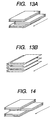
- the Offset output and the rotation output will now be described with reference to Figs. 13A, 13B, and 14 .
- Figs. 13A and 13B are diagrams for explaining the Offset output in the case where three copies of a document in which one copy is constructed by three pages are outputted.
- Fig. 13A shows an example in the case where all pages are deviated in a lump and outputted on a copy unit basis.
- An arrow in the diagram indicates the direction in which the papers are ejected from the printer.
- the diagram illustrates a state where the second copy is deviated from the first copy in the direction (lateral direction) which crosses perpendicularly to the printer ejecting direction and outputted. Further, the diagram shows a state where the third copy is outputted to the same position as that of the first copy so that it can be distinguished from the second copy.
- the copies are outputted by alternately changing the output positions every different copy.
- Fig. 13B shows a state where only the head page of each copy is deviated in the lateral direction and the papers are outputted. As mentioned above, it has been known that there are two kinds of methods in the Offset output.
- Fig. 14 is a diagram for explaining the rotation output in the case where three copies of a document in which one copy is constructed by three pages are outputted.
- An arrow in the diagram similarly indicates a direction in which the papers are ejected from the printer.
- the diagram shows a state where the second copy is rotated by 90° and the papers are outputted. As mentioned above, according to the rotation output, the output papers are rotated by 90° every different copy and the papers are outputted.
- each copy is Offset-output or rotation-output.
- the number of print papers to which one copy of the print data is equal to 1, it can be sorted without Offset-outputting or rotation-outputting.
- the print paper can be rather easily picked up and arranged.
- the invention is made in consideration of the above conventional techniques and it is a concern of the invention to provide an information processing apparatus, a print data generating method, and a print control program, in which when the Offset output or rotation sort output has been designated as an output style, whether document data of one copy is printed onto one sheet of paper (physical sheet) and outputted or not is discriminated, and in the case where the document data is printed to one sheet of paper, it is intended to generate print data which can set a printing such that the Offset output and the rotation output are not performed, and to also provide a computer-readable recording medium which stores such a program.
- an information processing apparatus comprising: finishing command setting means which can set a finishing command to a printer so as to rotation-sort-output or Offset-output document data; and counting means for counting the number of physical sheets to which the document data of one copy whose output is desired is allocated, wherein the finishing command setting means sets the finishing command in a manner such that in the case where the document data of one copy is printed onto one physical sheet as a result of the counting operation by the counting means, the rotation sort output or the Offset output is not performed, and in the case where the document data of one copy is printed onto two or more physical sheets, the rotation sort output or the Offset output is performed.
- Fig. 1 is a block diagram showing a construction of an information processing apparatus according to the first embodiment.
- reference numeral 1 denotes an information processing apparatus such as a personal computer (PC) or the like comprising, as main component elements: a video memory (hereinafter, VRAM) 3; a monitor 4; a keyboard (hereinafter, KBD) 5; a pointing device (hereinafter, PD) 6; a disk controller 7; a hard disk (hereinafter, HD) 9; a connector unit 10; a CPU 11; an RAM 12; and an ROM 13.
- VRAM video memory
- KBD keyboard
- PD pointing device
- HD hard disk
- the CPU 11 controls the whole information processing apparatus 1 in accordance with a program shown in Fig. 2 and the like, which will be explained hereinlater.
- the RAM 12 stores a program as a main memory of the CPU 11 and also has a temporary memory area for various data which is used as a work data area upon execution of the control by the CPU 11.
- the disk controller 7 performs a control of an access to an external memory such as HD 9, FD 8, or the like.
- the HD 9 and FD 8 are devices for recording data into a magnetic memory medium on a disk and reading and writing it to/from the medium.
- the HD 9 and FD 8 store: various document data such as text data, graphic data, and the like; further, a boot program of the information processing apparatus 1 which is downloaded into the RAM 12 and executed; an operating system (OS) as a control program of the CPU 11; various application programs; a printer control command (print data) generating program (printer driver); a present print system program having a synthesizing function and the like of the print data; and the like.
- the memory medium is not limited to the hard disk and the floppy disk but can be a magnetic tape, a CD-ROM, an IC memory card, a DVD, and the like.
- the ROM 13 is an internal memory in which various data and programs have been stored in a manner similar to the HD 9, FD 8, and the like as mentioned above.
- the monitor 4 displays a user interface (UI) such as various figures such as bit map data and the like, a command image or the like of command menu, messages from the operator, and the like in the information processing apparatus 1 onto a screen.
- UI user interface
- the monitor 4 comprises a CRT (Cathode Ray Tube), a liquid crystal, an FLC, or the like.
- the VRAM 3 stores data to be displayed on the monitor 4.
- the KBD 5 and PD 6 are operated by the operator and used for inputting various data, commands, print mode, or the like by the operator.
- the command image or the like of the command menu displayed on the screen of the monitor 4 is selected by the KBD 5 or PD 6, so that the execution of the command or the print mode can be instructed.
- the connector unit 10 is connected to a connector unit 17 of a printer 15 via a predetermined bidirectional interface 14 such as Centronics interface, network interface, or the like and executes a communication control process with the printer 15, which will be explained hereinlater, for example, executes transmission of a printer control command (print data) or the like.
- a predetermined bidirectional interface 14 such as Centronics interface, network interface, or the like
- the printer 15 comprises, as main component elements: a connector unit 17; a printer engine 18; an operation unit 19; an external memory 20; a CPU 21; an RAM 22; and an ROM 23. Those component elements are mutually connected via a system bus 16. Details of the component elements will be described hereinlater.
- the CPU 21 is a printer CPU for controlling the whole printer 15.
- the CPU 21 transmits an image signal to the printer engine 18 by the printer control command (print data) received by the connector unit 17 on the basis of a control program stored in the ROM 13 or external memory 20, which will be explained hereinlater.
- the RAM 22 has a temporary memory area for various data which is used as a work data area upon execution of the control by the CPU 21.
- the external memory 20 can be also connected as an option to the printer and stores font data, an emulation program, form data, and the like.
- the ROM 23 is a printer internal memory in which various data, the printer control program for controlling the printer, and the like have been stored in a manner similar to the external memory.
- the printer engine 18 is controlled by the CPU 21, receives the image signal generated through the system bus by the control program stored in the ROM 23 or external memory 20, and executes the actual printing.
- the operation unit 19 comprises: an input unit such as operation panel, operation switches, and the like; a display unit such as LED, liquid crystal panel, etc.; and the like.
- the operation unit 19 receives the operation of the operator and displays a result of the operation. The operator can designate and confirm the setting of the printer 15 through the operation unit 19.
- the connector unit 17 is connected to the connector unit 10 of the information processing apparatus 1 via the bidirectional interface 14 and can receive the printer control command and notify a state in the printer or the like.
- the printer 15 has: a paper feed unit for feeding the papers; paper ejecting bins on which the papers ejected from the printer 15 are stacked; a paper ejecting tray; and the like.
- the paper ejecting bins and paper ejecting tray can be used for the Offset output and the rotation output.
- the CPU executes a basic I/O program (BIOS), an operating system (OS), and a print processing program, so that the print processing apparatus operates.
- BIOS basic I/O program
- OS operating system
- print processing program a print processing program
- BIOS has been written in the ROM 13.
- the operating system (OS) has been written in the external memory such as HD 9, FD 8, or the like.
- the operating system (OS) stored in the external memory such as HD 9, FD 8, or the like is read out and loaded into the RAM 12 by an initial program loading (IPL) function in the BIOS and the OS is made operative.
- IPL initial program loading
- the operator selects the command image or the like on the command menu displayed on the screen of the monitor 4 by the KBD 5 and PD 6 and instructs the execution of an application.
- the application stored in the external memory such as HD 9, FD 8, or the like is read out and loaded into the RAM 12 and the application is made operative.
- the print processing module having the synthesizing function of the print data and the like and the printer control command generating program (printer driver) which have been stored in the external memory such as HD 9, FD 8, or the like are read out and loaded into the RAM 12 and the print processing system is made operative.
- Fig. 3 shows a construction of the recorded contents.
- the contents include volume information, directory information, a print processing execution file, a print processing related data file, and the like.
- the print processing module and the related data stored in the FD 8 can be also loaded into the information processing apparatus via the disk controller 7.
- the print processing module and the related data are read out from the FD 8 under the control of the OS and the BIOS and loaded into the RAM 12, so that they can be operated.
- Fig. 2 shows a memory map in a state where the print processing program has been loaded into the RAM 12 and can be executed.
- the BIOS, OS, print processing program, application program, related data, and work area are stored and formed in the RAM 12.
- the processes are started in a state where the program such as a printable application or the like is operating by the foregoing processing steps.
- an intermediate data writing program converts the document data received from the application into intermediate data, the intermediate data is temporarily stored as an intermediate data file, the total number (I) of logical pages is calculated, and further, a page information file in which page information including the calculated total number of pages is generated.
- the page information file is read, the number of physical sheets of the document data of one copy is calculated, and if the number of physical sheets is equal to 1, a command to turn off an Offset mode is set.
- an intermediate data output program outputs the intermediate data to the printer control command generating program (printer driver) or a program existing in the step at the front stage thereof.
- the printer control command generating program printer driver
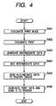
- Fig. 4 is a flowchart showing a flow of the print processing system in the embodiment.
- a print style, the number of pages, a layout order, the number of print copies, and the Offset mode as finishing command setting means for setting an output style are designated by the mode setting UI serving as print mode setting means for making the print processing system function.
- step S402 subsequently, the printing is designated.
- the designation of the print mode and the printing can be also instructed by a method whereby the system is operated by the KBD 5 and PD 6 in Fig. 1 mentioned above and the command image or the like on the command menu displayed on the screen of the monitor 4 is selected.
- step S403 follows and the intermediate data is generated.
- step S404 follows and the intermediate data is edited.
- Step S405 follows and the intermediate data is sent to the printer driver.
- step S406 the printer control command (print data) is generated and sent to the printer.
- This process is a normal printing step which is executed by the printer control command generating program (printer driver). The printing process is finished.
- step S401 the designating method of the print mode in step S401 will be described in detail with reference to Fig. 5 .
- Fig. 5 shows a print mode designating UI in case of designating the print mode in step S401 in Fig. 4 in the embodiment.
- (a) denotes a switch for designating the N-up printing as a print style.
- the switch (a) has a normal print button for designating the normal printing and an N-up print button for designating the N-up printing. Those switches are alternative switches and only one of them can be selected.
- Fig. 5 shows a state where the N-up printing has been selected and a check box of the N-up printing button is reversed in black.
- (f) denotes an OK button switch which is selected when the designated mode is determined.
- (g) denotes a cancel button which is selected when the designated mode and the designation of the print mode are cancelled.
- the information indicative of the print mode and the like is temporarily stored into the work area and can be referred to in a subsequent processing step.
- a duplex printing can be also instructed on the setting picture plane shown in Fig. 5 .
- a method for a plural-copy printing will be subsequently described with reference to Fig. 4 .
- the number of copies designated in (d) in Fig. 5 is referred to in the sending of the intermediate data in step S405 in Fig. 4 .
- it is realized by repeating an intermediate data sending process in step S405 the number of times corresponding to the number of copies designated in (d) in Fig. 5 .
- step S403 The method of generating the intermediate data in step S403 will now be described with reference to Figs. 6 and 7 .
- Fig. 6 shows a draw command of the document data which is transmitted to the information processing apparatus when the print execution is designated from the application or the like in step S402 in Fig. 4 of the embodiment.
- the draw command starts from a "job start command” and ends at a "job end command”.
- a printer initialization command appears next to the "job start command” and comprises a “finishing command", a "No. of copies command”, a “paper size command”, a “print direction command”, and the like.
- the "finishing command” includes an Offset designation command serving as an output style and the like.
- the draw command has a "print chr (print character) command", a "color command”, a “draw fig (draw figure) command”, a "draw image command”, a “form feed command”, and the like.
- the "color command” is a command for previously designating the colors in case of the "print chr command” and the "draw fig command”.
- the color of a character or a figure which is printed subsequently is designated by an RGB format.
- RGB format As a general image data format, a color data table of the RGB format is included in a data portion in the "draw image command”.
- the color of each pixel in case of drawing an image is designated by a method whereby each pixel value indicates an index of the color table.
- bit map data, information showing a width, a height, and coordinates of a drawing position, and the like are also included in the "draw image command”.
- information showing a character type, a character code, coordinates of a character printing position, a character width, a character height, a character feed width, a line feed height, and the like is included in the "print chr command”.
- a kind of drawing figure, an attribute of each of the drawing figures, information of the drawing position coordinates, and the like are also included in the "draw fig command”.
- Fig. 7 is a flowchart showing the intermediate data generating step in step S403 in Fig. 4 , that is, the step of generating the intermediate data from the draw command in Fig. 6 .
- step S701 in Fig. 7 a count value of a page counter (i) is initialized to 0.
- step S702 each draw command shown in Fig. 6 is sequentially received one by one from the first command and assumed to be M.
- step S703 whether the draw command M received in step S702 is the "job start command” or not is discriminated. If it is determined in step S703 that the received draw command M is the "job start command”, step S704 follows and the page information file for recording the page information is opened.
- next step S705 the intermediate data file to temporarily store the intermediate data of the first page is opened.
- step S706 the count value of the page counter (i) is set to (i + 1).
- step S707 a page number (i) and a file name Pi of the intermediate data temporary storage file opened in step S704 are recorded as page information.
- step S708 the received draw command M is converted into the intermediate data and recorded into the opened intermediate data temporary storage file.
- the processing routine is subsequently returned to step S702 and the next draw command is received and newly assumed to be M.
- step S709 follows and whether the received draw command M is the "form feed command" or not is discriminated.
- step S710 follows and the draw command M is converted into the intermediate data and recorded in a manner similar to step S708.
- step S711 follows and the opened intermediate data temporary storage file of the i-th page which has been recorded at present is closed.
- step S712 the count value of the page counter (i) is set to (i + 1).
- step S713 an intermediate data file to temporarily store the intermediate data of the i-th page is newly opened.
- step S714 the page number (i) and the file name Pi of the intermediate data temporary storage file opened in step S713 are recorded as page information.
- the processing routine is subsequently returned to step S702 and the next draw command is received and newly assumed to be M.
- step S715 follows and whether the received draw command M is the "job end command" or not is discriminated.
- step S715 If it is determined in step S715 that the received draw command M is not the "job end command", step S716 follows and the draw command M is converted into the intermediate data and recorded. The processing routine is returned to step S702 and the next draw command is received and newly assumed to be M.
- step S717 follows and the draw command M is converted into the intermediate data and recorded.
- step S718 follows and the intermediate data temporary storage file for temporarily storing the intermediate data which is referred to at present is closed.
- step S719 a page information temporary storage file in which the page information has been recorded is closed.
- the processing routine is finished.
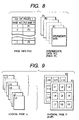
- Fig. 8 is a table showing a structure of the intermediate data temporary storage file of the embodiment. This table is stored into a storage device such as an HD 9 or the like in Fig. 1 .
- the temporary storage file comprises the page information temporary storage file for recording the page information and the temporary storage file for recording the intermediate data every page.
- the page information temporary storage file is a file which is recorded when the page information recording step in steps S707 and S714 in Fig. 7 , that is, the head page and form feed processes are executed.
- the present page number (i) and the file name Pi of the intermediate data temporary storage file corresponding to this page are recorded.
- a file name P1 is a file for recording the intermediate data of the first page.
- the count value of the page number counter (i) is updated every page information recording step.
- "I" is recorded as (i).
- the intermediate data temporary storage file is an area for recording the intermediate data obtained by replacing the draw command by another command format and formed every page divided by the "form feed command" or the like in the draw command in Fig. 6 mentioned above.
- the intermediate data can be also formed in a format obtained by collecting a plurality of draw commands into one command, or the like.
- step S404 in Fig. 4 will now be described with reference to a diagram of Fig. 9 and flowcharts of Figs. 10 and 11 .
- Fig. 9 is the diagram for explaining a page layout printing function in the intermediate data editing step in the embodiment.
- L1 to L17 denote logical pages Li.
- i 1 to 17 and an example of output pages of 17 pages is shown.
- F1 and F2 denote pages which are actually outputted to the printer, that is, physical pages Fi.
- a layout such that the data of each of the logical pages Li is reduced and allocated into one page of the physical sheet (output paper) is obtained.
- N denotes the number of N-up pages, that is, the number of logical pages which are arranged into one page of the physical sheet.
- N 9 (9-up) and nine logical pages are reduced and arranged into one page of the physical sheet.
- the layout order is set to "top, left ⁇ right"
- the top left position is set to the first page L1 of the logical pages
- the logical pages L2 and L3 are sequentially arranged to the right.
- the logical pages L4 and L5 are sequentially arranged to the right at the lower stage.
- the layout order in the N-up printing function is not limited to the above order.
- a layout order of "top, right ⁇ down ⁇ left column” or a layout of "top, left ⁇ down ⁇ right column” can be also used.
- the number (N) of logical pages which are arranged into one page of the physical sheet is not limited only to 9 pages (9-up) but can be also set to 2 pages (2-up), 4 pages (4-up), 8 pages (8-up), 16 pages (16-up), or the like.
- the number (I') of pages of the physical sheets Fi is expressed by the quotient of (I/N).
- a normal direct (equal magnification) copy output such that one logical page is arranged to one page of the physical sheet is performed in a manner similar to the case where the page layout is not performed.
- An intermediate data file in Fig. 8 is generated in order of the draw commands from the application in Fig. 6 .
- the page numbers of the intermediate data file coincide with those outputted by the application.
- Fig. 10 is the flowchart showing the intermediate data editing step in the embodiment.
- step S1001 the page information file which has temporarily been stored is opened.
- step S1002 follows and the page information is read out from the page information file.
- the total number (I) of pages, the file name Pi of the intermediate data recording file of each page, and the like are included in the page information.
- next step S1003 on the basis of the print mode in step S401 in Fig. 4 mentioned above, the number (N) of pages for the N-up printing as an optimum page layout printing is newly calculated.
- step S1004 as a layout set-up, as mentioned above, the logical pages Li are allocated to the page numbers of the intermediate data and a scaling ratio (reduction magnification) S of each of the logical pages Li at the time when they are arranged into the physical page is calculated.
- a scaling ratio (reduction magnification) S of each of the logical pages Li at the time when they are arranged into the physical page is calculated.
- Such an allocation is set by the operator at the time of the designation of the print mode in step S401 in Fig. 4 and the scaling ratio S is calculated on the basis of the set allocation.
- a process such that when the reverse order is designated, the logical pages Li are allocated in order opposite to that of the page numbers of the intermediate data file, or the like is executed.
- step S1005 the count value of the page counter (i) for counting the number of logical pages Li is initialized to "1".
- a count value of a counter (f) for counting the number of physical pages is also initialized to "1".
- the total number (I) of logical pages coincides with the number of pages of the intermediate data file.
- step S1019 follows and the command to designate the output style is set again in accordance with a situation.
- step S1020 As an end of the job, the job end code is outputted at the last of the intermediate data file corresponding to the logical page LI.
- next step S1021 the page information file is closed and the processing routine is finished.
- step S1007 follows and a position (reference position) for arranging the logical pages Li to the physical page is calculated.
- the reference position denotes coordinates showing a position in the physical page where, for example, the coordinates of the top left logical page are arranged, or the like.
- the reference position is determined on the basis of the number N of logical pages Li to be arranged to one physical page which was calculated in step S1003, the layout order, and the target logical page among the logical pages Li.
- the number N of logical pages Li to be arranged to one physical page which was calculated in step S1003, the layout order, and the target logical page among the logical pages Li In the example of the explanation of the physical page in Fig.
- next step S1008 the intermediate data file corresponding to the logical pages Li is opened.
- step S1009 records of the intermediate data are sequentially read and assumed to be "R".
- step S1010 whether the intermediate data R read in step S1009 indicates the "form feed” or "job end” is discriminated.
- step S1010 If it is determined in step S1010 that the intermediate data R does not indicate the "form feed” or "job end”, step S1011 follows and a replacing process of the read intermediate data R is executed.
- the intermediate data is not replaced and the processing routine can also directly advance to the next step.
- step S1012 the intermediate data R replaced in step S1011 is assumed to be R' and outputted to the intermediate data file and edited in accordance with the scaling ratio S and the position which were calculated in step S1004.
- step S1009 a record of the next intermediate data is obtained and newly set to R.
- Mod(i, N) is a function for calculating a remainder obtained by dividing the present count value of the logical page counter (i) by the number (N) of logical pages to be arranged to one physical page.
- step S1014 follows and the intermediate data file corresponding to the logical page Li which is at present open is closed.
- the processing routine is returned to step S1006 mentioned above.
- step S1017 the intermediate data file corresponding to the logical page Li which is at present open is closed.
- the processing routine is returned to step S1006 mentioned above and whether the processing routine is finished or not is discriminated.
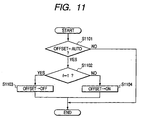
- Fig. 11 is the flowchart showing a step of automatically setting an Offset command in the embodiment.
- step S1101 whether the Offset mode designated in step S401 in Fig. 4 is Auto or not is discriminated.
- step S1101 If the Offset mode is not Auto in step S1101, the Offset command is finished without changing the number of pages designated in step S401 in Fig. 4 .
- step S1102 follows and whether the count value of the physical page counter (f) is equal to 1 or not is discriminated.
- step S1103 follows and the Offset command is reset to OFF and the processing routine is finished.
- step S1104 follows and the Offset command is reset to ON and the processing routine is finished.
- the intermediate data writing program converts the document data received from the application into the intermediate data, temporarily stores the intermediate data as an intermediate data file, calculates the total number (I) of logical pages, and further, generates a page information file in which the page information including the total number of logical pages has been recorded.
- the page information file is read, the number of physical sheets of the print data of one copy is calculated, and if the number of physical sheets is equal to 1, the command is set again so as to cancel the rotation output mode.
- the intermediate data output program outputs the intermediate data to the printer control command generating program (printer driver) or the program existing in the step at the front stage thereof.
- the printer control command generating program (printer driver) finally generates the printer control command (print data) and prints.
- the second embodiment can be similarly realized by changing the designation of the Offset mode in the explanatory diagram of UI in Fig. 5 to the designation of the rotation output mode and, further, replacing the Offset command to the rotation command in each step in Fig. 11 .
- the Offset mode is Auto
- a control is made so as to set the Offset command in accordance with the value of the physical page counter.
- the modification has a construction such that if the Auto mode shown in Fig. 5 is not provided, that is, when only ON or OFF exists as a setting mode of the Offset mode, it is intended to obtain an effect similar to that in the first embodiment.
- step S1201 the Offset command is finished without changing the number of pages designated in step S401 in Fig. 4 .
- step S1202 follows and whether the count value of the physical page counter (f) is equal to 1 or not is discriminated.
- step S1202 If f ⁇ 1 in step S1202, the Offset command is held to be ON without changing. The processing routine is finished.
- step S1203 follows and the Offset command is set to OFF again and the processing routine is finished.
- control of the modification can be applied to the rotation output mode described in the second embodiment.
- the invention can be also applied to a system constructed by a plurality of apparatuses or can be also applied to an apparatus comprising one equipment.
- the invention can be also applied to a case where it is accomplished by supplying a program for controlling the printing to a system or an apparatus.
- a computer-readable recording medium in which the program according to the invention has been stored constructs the invention.
- the system or apparatus operates in accordance with a predetermined method.
- the medium for recording the present print processing program is not limited to the floppy disk but can also use a magnetic tape, a CD-ROM, an IC memory card, a DVD, or the like.
- the embodiment can be applied also to an information processing apparatus for transmitting the print data to the printer having the duplex printing function. If the printer has the duplex printing function and a duplex printing mode is designated, the information processing apparatus discriminates whether the document data (print data) of one copy is arranged to one page of the physical sheet or not.
- the print data of one copy is arranged to one physical sheet.
- the print data of one copy is arranged to one physical sheet, by performing a control such that the Offset output and the rotation output are not performed, an effect similar to that of the invention can be obtained.
- the Offset or rotation output has been designated as an output style, whether the number of copy papers to which the document data of one copy is printed is equal to 1 or not is discriminated. If YES, the process is automatically executed lest the Offset or rotation output is performed. Therefore, in case of printing the document data by a plurality of copies, a problem such that if it is Offset- and rotation-outputted every paper, the papers become bulky and it is difficult to sort them can be solved. Further, even if the page layout such as N-up or the like has been set, since the number of output papers can be counted, processes similar to those mentioned above can be executed. The above problem can be solved.
- the Offset print mode or rotation print mode has been set as a print mode
- whether the number of papers to which the print data of one copy is printed is equal to 1 or not is discriminated. If YES, the print data such that the Offset printing and rotation printing are not executed can be generated.
Landscapes
- Engineering & Computer Science (AREA)
- Theoretical Computer Science (AREA)
- Physics & Mathematics (AREA)
- General Engineering & Computer Science (AREA)
- General Physics & Mathematics (AREA)
- Human Computer Interaction (AREA)
- Record Information Processing For Printing (AREA)
Claims (10)
- Informationsverarbeitungsvorrichtung (1), umfassend:eine Endbearbeitungsbefehleinstelleinrichtung (e), die einen Endbearbeitungsbefehl für einen Drucker (15) zur Drehsortierausgabe oder Versatzausgabe von Dokumentendaten einstellen kann; undeine Zähleinrichtung (11) zum Zählen der Anzahl physischer Bögen, denen die Dokumentendaten einer Kopie, deren Ausgabe gewünscht ist, zugeordnet sind,wobei die Endbearbeitungsbefehleinstelleinrichtung (e) den Endbearbeitungsbefehl in der Weise einstellt, dass für den Fall, dass die Dokumentendaten einer Kopie als Ergebnis der Zählung durch die Zähleinrichtung auf einem physischen Bogen gedruckt werden, die Drehsortierausgabe oder die Versatzausgabe nicht durchgeführt wird (S1103), und für den Fall, dass die Dokumentendaten einer Kopie auf zwei oder mehr physische Bögen gedruckt werden, die Drehsortierausgabe oder die Versatzausgabe durchgeführt wird (S1104).
- Vorrichtung (1) nach Anspruch 1, ferner umfassend:eine Druckmoduseinstelleinrichtung (a) zum Einstellen eines Druckmodus der Dokumentendaten,wobei die Druckmoduseinstelleinrichtung (a) eine Layoutdruckeinstelleinrichtung zum Anordnen mehrerer logischer Seiten auf einer Seite des physischen Bogens aufweist.
- Vorrichtung (1) nach Anspruch 2, ferner umfassend:eine Druckanweisungseinrichtung (f) zum Anweisen der Ausführung eines Drucks; undeine Spooleinrichtung zum Spoolen der Dokumentendaten als Zwischendaten eines vom Datenformat der Dokumentdaten verschiedenen Datenformats,wobei die Zähleinrichtung (11) das Zählen auf der Grundlage der von der Spooleinrichtung aufgespoolten Zwischendaten ausführt.
- Vorrichtung (1) nach Anspruch 3, ferner umfassend:eine Zwischendatenseiteneditiereinrichtung zum Erstellen einer Layoutdrucksteuerung der Zwischendaten (S404) auf der Grundlage der von der Zähleinrichtung gezählten Zahl und des von der Druckmoduseinstelleinrichtung eingestellten Druckmodus;eine Zwischendatenausgabeeinrichtung zum Ausgeben (S405) der editierten Zwischendaten; undeine Druckdatenerzeugungseinrichtung zum Erzeugen (S406) von Druckdaten aus den ausgegebenen Zwischendaten.
- Druckdatenerzeugungsverfahren, umfassend:einen Endbearbeitungsbefehleinstellschritt, der einen Endbearbeitungsbefehl für einen Drucker (15) zur Drehsortierausgabe oder einer Versatzausgabe von Dokumentendaten einstellen kann; undeinen Zählschritt zum Zählen der Anzahl physischer Bögen, denen die Dokumentendaten einer Kopie, deren Ausgabe gewünscht ist, zugeordnet sind,wobei im Endbearbeitungsbefehleinstellschritt der Endbearbeitungsbefehl in der Weise eingestellt wird, dass für den Fall, dass die Dokumentendaten einer Kopie als Ergebnis der Zählung im Zählschritt auf einen physischen Bogen gedruckt werden, die Drehsortierausgabe oder die Versatzausgabe nicht durchgeführt wird (S1103), und für den Fall, dass die Dokumentendaten einer Kopie auf zwei oder mehr physische Bögen gedruckt werden, die Drehsortierausgabe oder die Versatzausgabe durchgeführt wird (S1104).
- Verfahren nach Anspruch 5, ferner umfassend einen Druckmoduseinstellschritt zum Einstellen eines Druckmodus der Dokumentendaten,
wobei der Druckmoduseinstellschritt ferner einen Layoutdruckeinstellschritt zum Anordnen mehrerer logischer Seiten auf einer Seite des physischen Bogens aufweist. - Verfahren nach Anspruch 6, ferner umfassend:einen Druckanweisungsschritt (S401) zum Anweisen der Ausführung eines Drucks; undeinen Spoolschritt (S403) zum Spoolen der Dokumentendaten als Zwischendaten eines vom Datenformat der Dokumentendaten verschiedenen Datenformats,wobei die Anzahl physischer Bögen im Zählschritt auf der Grundlage der vom Spoolschritt gespoolten Zwischendaten gezählt wird.
- Verfahren nach Anspruch 7, ferner umfassend:einen Zwischendatenseiteneditierschritt (S404) zum Erstellen einer Layoutdrucksteuerung der Zwischendaten auf der Grundlage der vom Zählschritt gezählten Anzahl und des vom Druckmoduseinstellschritt (S401) eingestellten Druckmodus;einen Zwischendatenausgabeschritt zum Ausgeben der editierten Zwischendaten (S405); undeinen Druckdatenerzeugungsschritt (S406) zum Erzeugen von Druckdaten aus den ausgegebenen Zwischendaten.
- Drucksteuerprogramm, welches bei Ausführung durch eine Informationsverarbeitungsvorrichtung diese veranlasst, ein Verfahren nach einem der Ansprüche 5 bis 8 durchzuführen.
- Computerlesbares Speichermedium, welches ein Programm nach Anspruch 9 speichert.
Applications Claiming Priority (4)
| Application Number | Priority Date | Filing Date | Title |
|---|---|---|---|
| JP2000396173 | 2000-12-26 | ||
| JP2000396173 | 2000-12-26 | ||
| JP2001336847A JP3884943B2 (ja) | 2000-12-26 | 2001-11-01 | 情報処理装置、印刷データ生成方法、印刷制御プログラム及びコンピュータ読み取り可能な記録媒体 |
| JP2001336847 | 2001-11-01 |
Publications (3)
| Publication Number | Publication Date |
|---|---|
| EP1220144A2 EP1220144A2 (de) | 2002-07-03 |
| EP1220144A3 EP1220144A3 (de) | 2004-04-07 |
| EP1220144B1 true EP1220144B1 (de) | 2012-08-08 |
Family
ID=26606739
Family Applications (1)
| Application Number | Title | Priority Date | Filing Date |
|---|---|---|---|
| EP01310605A Expired - Lifetime EP1220144B1 (de) | 2000-12-26 | 2001-12-19 | Endbearbeitungsbefehlinterpretierung in Abhängigkeit der Länge des Jobs |
Country Status (5)
| Country | Link |
|---|---|
| US (2) | US7233411B2 (de) |
| EP (1) | EP1220144B1 (de) |
| JP (1) | JP3884943B2 (de) |
| KR (1) | KR100469595B1 (de) |
| CN (1) | CN1213383C (de) |
Families Citing this family (21)
| Publication number | Priority date | Publication date | Assignee | Title |
|---|---|---|---|---|
| JP3884943B2 (ja) * | 2000-12-26 | 2007-02-21 | キヤノン株式会社 | 情報処理装置、印刷データ生成方法、印刷制御プログラム及びコンピュータ読み取り可能な記録媒体 |
| US20030226005A1 (en) * | 2002-05-28 | 2003-12-04 | Vincent Wu | Bootable CD controller with embedded operating system |
| JP4574344B2 (ja) * | 2004-01-20 | 2010-11-04 | キヤノン株式会社 | 情報処理装置及び方法 |
| JP4756870B2 (ja) * | 2005-02-03 | 2011-08-24 | キヤノン株式会社 | 文書処理装置及び文書処理方法並びにプログラム |
| JP4313334B2 (ja) * | 2005-05-23 | 2009-08-12 | シャープ株式会社 | 印刷制御プログラム、印刷装置の制御方法および前記プログラムを備えてなる印刷制御装置 |
| JP4604888B2 (ja) * | 2005-07-12 | 2011-01-05 | 富士ゼロックス株式会社 | 位置情報管理装置、画像形成装置、位置情報管理方法、及びプログラム |
| US8174727B2 (en) * | 2006-03-09 | 2012-05-08 | Kabushiki Kaisha Toshiba | Image forming apparatus that displays finished graphical image indicating multiple draft images arranged in matrix form |
| JP2007279832A (ja) * | 2006-04-03 | 2007-10-25 | Canon Inc | 情報処理装置および情報処理方法および情報処理プログラム |
| JP5034659B2 (ja) * | 2007-04-30 | 2012-09-26 | ブラザー工業株式会社 | 画像形成装置 |
| CN102202903B (zh) * | 2008-11-05 | 2013-08-28 | 惠普开发有限公司 | 一种打印设备及产生至少一个首片材作业偏移的方法 |
| JP4605296B2 (ja) * | 2009-06-09 | 2011-01-05 | ブラザー工業株式会社 | 印刷データ処理プログラムおよび印刷データ処理装置 |
| US8553260B2 (en) * | 2009-09-28 | 2013-10-08 | Csr Imaging Us, Lp | Preview and modification of printable components of a document at a printing device |
| JP5610781B2 (ja) * | 2010-01-21 | 2014-10-22 | キヤノン株式会社 | 情報処理装置、情報処理方法及びプログラム |
| JP5630072B2 (ja) * | 2010-05-24 | 2014-11-26 | 富士ゼロックス株式会社 | 印刷管理装置、印刷管理システム及びプログラム |
| JP5871525B2 (ja) * | 2011-08-30 | 2016-03-01 | キヤノン株式会社 | 情報処理装置、その制御方法、および制御プログラム |
| JP5539280B2 (ja) * | 2011-09-07 | 2014-07-02 | キヤノン株式会社 | データ処理装置、データ処理方法およびプログラム |
| JP5807475B2 (ja) * | 2011-09-21 | 2015-11-10 | 富士ゼロックス株式会社 | 画像形成装置、画像形成システム及び制御プログラム |
| JP5921156B2 (ja) | 2011-11-16 | 2016-05-24 | キヤノン株式会社 | 印刷装置、レイアウト変更方法、及びプログラム |
| JP5847560B2 (ja) * | 2011-11-28 | 2016-01-27 | キヤノン株式会社 | 印刷制御装置、その制御方法、及びプログラム |
| JP2017149110A (ja) * | 2016-02-26 | 2017-08-31 | 富士ゼロックス株式会社 | 印刷装置及びプログラム |
| JP7182868B2 (ja) * | 2017-12-22 | 2022-12-05 | キヤノン株式会社 | シート仕分け装置及び画像形成装置 |
Family Cites Families (22)
| Publication number | Priority date | Publication date | Assignee | Title |
|---|---|---|---|---|
| US85870A (en) | 1869-01-12 | Improvement in harvester-rakes | ||
| US4188025A (en) * | 1978-02-23 | 1980-02-12 | Eastman Kodak Company | Offset sheet stacking apparatus |
| US4917366A (en) * | 1986-02-25 | 1990-04-17 | Canon Kabushiki Kaisha | Sheet handling apparatus |
| US5007625A (en) * | 1989-08-24 | 1991-04-16 | Xerox Corporation | Selectable sheet offsetting |
| JPH0564925A (ja) | 1991-09-09 | 1993-03-19 | Ricoh Co Ltd | 画像形成装置 |
| US5495561A (en) * | 1993-06-21 | 1996-02-27 | Taligent, Inc. | Operating system with object-oriented printing interface |
| US5501442A (en) * | 1993-11-08 | 1996-03-26 | Xerox Corporation | Dual mode tamper/offsetter |
| JP3040904B2 (ja) * | 1993-12-24 | 2000-05-15 | キヤノン株式会社 | シート後処理装置及びこれを備える画像形成装置 |
| US5602974A (en) * | 1994-10-05 | 1997-02-11 | Microsoft Corporation | Device independent spooling in a print architecture |
| US5768488A (en) | 1995-02-24 | 1998-06-16 | International Business Machines Corporation | Enhanced page placement for multiple-up presentation |
| KR100212981B1 (ko) * | 1995-03-04 | 1999-08-02 | 윤종용 | 화상형성장치의 출력용지 및 토너 절약 프린팅 장치 및 방법 |
| JPH08262931A (ja) | 1995-03-22 | 1996-10-11 | Toshiba Corp | 画像形成装置および画像形成方法 |
| JP3486528B2 (ja) | 1997-07-22 | 2004-01-13 | キヤノン株式会社 | プリンタドライバ、プリンタ制御方法および印刷方法 |
| KR19990084815A (ko) * | 1998-05-11 | 1999-12-06 | 윤종용 | 다중 페이지 동시 인쇄 방법 |
| US6671066B1 (en) * | 1998-07-28 | 2003-12-30 | Minolta Co., Ltd. | Computer program product intended for processing print data, and apparatus and method for processing print data |
| KR100311027B1 (ko) * | 1998-09-19 | 2001-11-15 | 윤종용 | 멀티페이지 인쇄방법 |
| KR20000059460A (ko) * | 1999-03-04 | 2000-10-05 | 윤종용 | 복합기의 축소 복사 방법 |
| KR100296590B1 (ko) * | 1999-04-07 | 2001-07-12 | 윤종용 | 프린터의 인쇄 각도 가변 방법 |
| JP2001039614A (ja) * | 1999-07-30 | 2001-02-13 | Canon Inc | 画像形成装置 |
| JP3634695B2 (ja) * | 1999-11-02 | 2005-03-30 | キヤノン株式会社 | 印刷制御方法および装置 |
| JP4489936B2 (ja) * | 2000-12-12 | 2010-06-23 | セイコーエプソン株式会社 | 印刷装置および印刷方法 |
| JP3884943B2 (ja) * | 2000-12-26 | 2007-02-21 | キヤノン株式会社 | 情報処理装置、印刷データ生成方法、印刷制御プログラム及びコンピュータ読み取り可能な記録媒体 |
-
2001
- 2001-11-01 JP JP2001336847A patent/JP3884943B2/ja not_active Expired - Fee Related
- 2001-12-14 US US10/014,430 patent/US7233411B2/en not_active Expired - Lifetime
- 2001-12-19 EP EP01310605A patent/EP1220144B1/de not_active Expired - Lifetime
- 2001-12-24 KR KR10-2001-0084032A patent/KR100469595B1/ko not_active Expired - Fee Related
- 2001-12-25 CN CNB011440163A patent/CN1213383C/zh not_active Expired - Fee Related
-
2007
- 2007-05-16 US US11/749,492 patent/US8009300B2/en not_active Expired - Fee Related
Also Published As
| Publication number | Publication date |
|---|---|
| CN1213383C (zh) | 2005-08-03 |
| KR100469595B1 (ko) | 2005-02-02 |
| CN1361502A (zh) | 2002-07-31 |
| EP1220144A3 (de) | 2004-04-07 |
| EP1220144A2 (de) | 2002-07-03 |
| US20020080405A1 (en) | 2002-06-27 |
| KR20020052986A (ko) | 2002-07-04 |
| JP2002259090A (ja) | 2002-09-13 |
| US20070211297A1 (en) | 2007-09-13 |
| US7233411B2 (en) | 2007-06-19 |
| JP3884943B2 (ja) | 2007-02-21 |
| US8009300B2 (en) | 2011-08-30 |
Similar Documents
| Publication | Publication Date | Title |
|---|---|---|
| EP1220144B1 (de) | Endbearbeitungsbefehlinterpretierung in Abhängigkeit der Länge des Jobs | |
| US8305621B2 (en) | Printing using multiple paper sources | |
| JP3513266B2 (ja) | 印刷制御システム、印刷制御方法及び印刷処理方法 | |
| US7072071B2 (en) | Printing control system, printing control method and storage medium | |
| US20050105116A1 (en) | Document processing apparatus and document processing method | |
| US8144345B2 (en) | Information-processing apparatus and method | |
| EP1076311B1 (de) | Drucker mit Buchbindefunktion für das Binden von Druckschriften | |
| EP1150200A2 (de) | Drucksteuergerät und Speichermedium | |
| JP2005071187A (ja) | 文書変換方法及び装置 | |
| US7428072B2 (en) | Printing control program, printing control method, printing system and information processing apparatus | |
| JP2005115683A (ja) | 印刷設定方法及び情報処理装置 | |
| JP5084649B2 (ja) | 情報処理装置及び情報処理方法及びプログラム | |
| JP2002014797A (ja) | 情報処理装置、印刷制御装置、およびその制御方法、および記憶媒体、およびその制御プログラム | |
| EP1220145B1 (de) | Ausdruck in mehreren Ausgabeformaten | |
| US20020075498A1 (en) | Information processing apparatus, method of processing data by an information processing apparatus, data processing program, and storage medium including a data processing program stored thereon | |
| US8400669B2 (en) | Information processing apparatus and staple attribute setting method | |
| US8160469B2 (en) | Information processing apparatus, method for controlling the information processing apparatus, and storage medium | |
| US20120287445A1 (en) | Information processing apparatus, imposition method, and storage medium | |
| JP2008027218A (ja) | 文書処理方法及びそのシステム |
Legal Events
| Date | Code | Title | Description |
|---|---|---|---|
| PUAI | Public reference made under article 153(3) epc to a published international application that has entered the european phase |
Free format text: ORIGINAL CODE: 0009012 |
|
| AK | Designated contracting states |
Kind code of ref document: A2 Designated state(s): AT BE CH CY DE DK ES FI FR GB GR IE IT LI LU MC NL PT SE TR |
|
| AX | Request for extension of the european patent |
Free format text: AL;LT;LV;MK;RO;SI |
|
| PUAL | Search report despatched |
Free format text: ORIGINAL CODE: 0009013 |
|
| AK | Designated contracting states |
Kind code of ref document: A3 Designated state(s): AT BE CH CY DE DK ES FI FR GB GR IE IT LI LU MC NL PT SE TR |
|
| AX | Request for extension of the european patent |
Extension state: AL LT LV MK RO SI |
|
| RIC1 | Information provided on ipc code assigned before grant |
Ipc: 7G 03G 15/00 B Ipc: 7G 06F 3/12 B Ipc: 7G 06K 15/00 A |
|
| 17P | Request for examination filed |
Effective date: 20040819 |
|
| AKX | Designation fees paid |
Designated state(s): DE FR GB IT |
|
| 17Q | First examination report despatched |
Effective date: 20110324 |
|
| GRAP | Despatch of communication of intention to grant a patent |
Free format text: ORIGINAL CODE: EPIDOSNIGR1 |
|
| GRAS | Grant fee paid |
Free format text: ORIGINAL CODE: EPIDOSNIGR3 |
|
| GRAA | (expected) grant |
Free format text: ORIGINAL CODE: 0009210 |
|
| AK | Designated contracting states |
Kind code of ref document: B1 Designated state(s): DE FR GB IT |
|
| REG | Reference to a national code |
Ref country code: GB Ref legal event code: FG4D |
|
| REG | Reference to a national code |
Ref country code: DE Ref legal event code: R096 Ref document number: 60146943 Country of ref document: DE Effective date: 20121011 |
|
| PGFP | Annual fee paid to national office [announced via postgrant information from national office to epo] |
Ref country code: FR Payment date: 20121009 Year of fee payment: 12 |
|
| PGFP | Annual fee paid to national office [announced via postgrant information from national office to epo] |
Ref country code: GB Payment date: 20121221 Year of fee payment: 12 |
|
| PGFP | Annual fee paid to national office [announced via postgrant information from national office to epo] |
Ref country code: DE Payment date: 20121231 Year of fee payment: 12 |
|
| PG25 | Lapsed in a contracting state [announced via postgrant information from national office to epo] |
Ref country code: IT Free format text: LAPSE BECAUSE OF FAILURE TO SUBMIT A TRANSLATION OF THE DESCRIPTION OR TO PAY THE FEE WITHIN THE PRESCRIBED TIME-LIMIT Effective date: 20120808 |
|
| PLBE | No opposition filed within time limit |
Free format text: ORIGINAL CODE: 0009261 |
|
| STAA | Information on the status of an ep patent application or granted ep patent |
Free format text: STATUS: NO OPPOSITION FILED WITHIN TIME LIMIT |
|
| 26N | No opposition filed |
Effective date: 20130510 |
|
| REG | Reference to a national code |
Ref country code: DE Ref legal event code: R097 Ref document number: 60146943 Country of ref document: DE Effective date: 20130510 |
|
| REG | Reference to a national code |
Ref country code: DE Ref legal event code: R119 Ref document number: 60146943 Country of ref document: DE |
|
| GBPC | Gb: european patent ceased through non-payment of renewal fee |
Effective date: 20131219 |
|
| REG | Reference to a national code |
Ref country code: FR Ref legal event code: ST Effective date: 20140829 |
|
| REG | Reference to a national code |
Ref country code: DE Ref legal event code: R119 Ref document number: 60146943 Country of ref document: DE Effective date: 20140701 |
|
| PG25 | Lapsed in a contracting state [announced via postgrant information from national office to epo] |
Ref country code: DE Free format text: LAPSE BECAUSE OF NON-PAYMENT OF DUE FEES Effective date: 20140701 |
|
| PG25 | Lapsed in a contracting state [announced via postgrant information from national office to epo] |
Ref country code: FR Free format text: LAPSE BECAUSE OF NON-PAYMENT OF DUE FEES Effective date: 20131231 Ref country code: GB Free format text: LAPSE BECAUSE OF NON-PAYMENT OF DUE FEES Effective date: 20131219 |