EP1217249A1 - Schwingungsdämpfendes Lager und Kraftfahrzeug mit einem solchen Lager - Google Patents
Schwingungsdämpfendes Lager und Kraftfahrzeug mit einem solchen Lager Download PDFInfo
- Publication number
- EP1217249A1 EP1217249A1 EP01403254A EP01403254A EP1217249A1 EP 1217249 A1 EP1217249 A1 EP 1217249A1 EP 01403254 A EP01403254 A EP 01403254A EP 01403254 A EP01403254 A EP 01403254A EP 1217249 A1 EP1217249 A1 EP 1217249A1
- Authority
- EP
- European Patent Office
- Prior art keywords
- annular
- frame
- reinforcement
- elastomer
- central axis
- Prior art date
- Legal status (The legal status is an assumption and is not a legal conclusion. Google has not performed a legal analysis and makes no representation as to the accuracy of the status listed.)
- Granted
Links
Images


Classifications
-
- F—MECHANICAL ENGINEERING; LIGHTING; HEATING; WEAPONS; BLASTING
- F16—ENGINEERING ELEMENTS AND UNITS; GENERAL MEASURES FOR PRODUCING AND MAINTAINING EFFECTIVE FUNCTIONING OF MACHINES OR INSTALLATIONS; THERMAL INSULATION IN GENERAL
- F16F—SPRINGS; SHOCK-ABSORBERS; MEANS FOR DAMPING VIBRATION
- F16F13/00—Units comprising springs of the non-fluid type as well as vibration-dampers, shock-absorbers, or fluid springs
- F16F13/04—Units comprising springs of the non-fluid type as well as vibration-dampers, shock-absorbers, or fluid springs comprising both a plastics spring and a damper, e.g. a friction damper
- F16F13/06—Units comprising springs of the non-fluid type as well as vibration-dampers, shock-absorbers, or fluid springs comprising both a plastics spring and a damper, e.g. a friction damper the damper being a fluid damper, e.g. the plastics spring not forming a part of the wall of the fluid chamber of the damper
- F16F13/08—Units comprising springs of the non-fluid type as well as vibration-dampers, shock-absorbers, or fluid springs comprising both a plastics spring and a damper, e.g. a friction damper the damper being a fluid damper, e.g. the plastics spring not forming a part of the wall of the fluid chamber of the damper the plastics spring forming at least a part of the wall of the fluid chamber of the damper
- F16F13/14—Units of the bushing type, i.e. loaded predominantly radially
- F16F13/16—Units of the bushing type, i.e. loaded predominantly radially specially adapted for receiving axial loads
-
- B—PERFORMING OPERATIONS; TRANSPORTING
- B60—VEHICLES IN GENERAL
- B60G—VEHICLE SUSPENSION ARRANGEMENTS
- B60G21/00—Interconnection systems for two or more resiliently-suspended wheels, e.g. for stabilising a vehicle body with respect to acceleration, deceleration or centrifugal forces
- B60G21/02—Interconnection systems for two or more resiliently-suspended wheels, e.g. for stabilising a vehicle body with respect to acceleration, deceleration or centrifugal forces permanently interconnected
- B60G21/04—Interconnection systems for two or more resiliently-suspended wheels, e.g. for stabilising a vehicle body with respect to acceleration, deceleration or centrifugal forces permanently interconnected mechanically
- B60G21/05—Interconnection systems for two or more resiliently-suspended wheels, e.g. for stabilising a vehicle body with respect to acceleration, deceleration or centrifugal forces permanently interconnected mechanically between wheels on the same axle but on different sides of the vehicle, i.e. the left and right wheel suspensions being interconnected
- B60G21/051—Trailing arm twist beam axles
- B60G21/052—Mounting means therefor
-
- B—PERFORMING OPERATIONS; TRANSPORTING
- B60—VEHICLES IN GENERAL
- B60G—VEHICLE SUSPENSION ARRANGEMENTS
- B60G7/00—Pivoted suspension arms; Accessories thereof
- B60G7/02—Attaching arms to sprung part of vehicle
-
- F—MECHANICAL ENGINEERING; LIGHTING; HEATING; WEAPONS; BLASTING
- F16—ENGINEERING ELEMENTS AND UNITS; GENERAL MEASURES FOR PRODUCING AND MAINTAINING EFFECTIVE FUNCTIONING OF MACHINES OR INSTALLATIONS; THERMAL INSULATION IN GENERAL
- F16F—SPRINGS; SHOCK-ABSORBERS; MEANS FOR DAMPING VIBRATION
- F16F1/00—Springs
- F16F1/36—Springs made of rubber or other material having high internal friction, e.g. thermoplastic elastomers
- F16F1/38—Springs made of rubber or other material having high internal friction, e.g. thermoplastic elastomers with a sleeve of elastic material between a rigid outer sleeve and a rigid inner sleeve or pin, i.e. bushing-type
- F16F1/387—Springs made of rubber or other material having high internal friction, e.g. thermoplastic elastomers with a sleeve of elastic material between a rigid outer sleeve and a rigid inner sleeve or pin, i.e. bushing-type comprising means for modifying the rigidity in particular directions
-
- F—MECHANICAL ENGINEERING; LIGHTING; HEATING; WEAPONS; BLASTING
- F16—ENGINEERING ELEMENTS AND UNITS; GENERAL MEASURES FOR PRODUCING AND MAINTAINING EFFECTIVE FUNCTIONING OF MACHINES OR INSTALLATIONS; THERMAL INSULATION IN GENERAL
- F16F—SPRINGS; SHOCK-ABSORBERS; MEANS FOR DAMPING VIBRATION
- F16F13/00—Units comprising springs of the non-fluid type as well as vibration-dampers, shock-absorbers, or fluid springs
- F16F13/04—Units comprising springs of the non-fluid type as well as vibration-dampers, shock-absorbers, or fluid springs comprising both a plastics spring and a damper, e.g. a friction damper
- F16F13/06—Units comprising springs of the non-fluid type as well as vibration-dampers, shock-absorbers, or fluid springs comprising both a plastics spring and a damper, e.g. a friction damper the damper being a fluid damper, e.g. the plastics spring not forming a part of the wall of the fluid chamber of the damper
- F16F13/08—Units comprising springs of the non-fluid type as well as vibration-dampers, shock-absorbers, or fluid springs comprising both a plastics spring and a damper, e.g. a friction damper the damper being a fluid damper, e.g. the plastics spring not forming a part of the wall of the fluid chamber of the damper the plastics spring forming at least a part of the wall of the fluid chamber of the damper
- F16F13/14—Units of the bushing type, i.e. loaded predominantly radially
- F16F13/1409—Units of the bushing type, i.e. loaded predominantly radially characterised by buffering features or stoppers
-
- F—MECHANICAL ENGINEERING; LIGHTING; HEATING; WEAPONS; BLASTING
- F16—ENGINEERING ELEMENTS AND UNITS; GENERAL MEASURES FOR PRODUCING AND MAINTAINING EFFECTIVE FUNCTIONING OF MACHINES OR INSTALLATIONS; THERMAL INSULATION IN GENERAL
- F16F—SPRINGS; SHOCK-ABSORBERS; MEANS FOR DAMPING VIBRATION
- F16F13/00—Units comprising springs of the non-fluid type as well as vibration-dampers, shock-absorbers, or fluid springs
- F16F13/04—Units comprising springs of the non-fluid type as well as vibration-dampers, shock-absorbers, or fluid springs comprising both a plastics spring and a damper, e.g. a friction damper
- F16F13/06—Units comprising springs of the non-fluid type as well as vibration-dampers, shock-absorbers, or fluid springs comprising both a plastics spring and a damper, e.g. a friction damper the damper being a fluid damper, e.g. the plastics spring not forming a part of the wall of the fluid chamber of the damper
- F16F13/08—Units comprising springs of the non-fluid type as well as vibration-dampers, shock-absorbers, or fluid springs comprising both a plastics spring and a damper, e.g. a friction damper the damper being a fluid damper, e.g. the plastics spring not forming a part of the wall of the fluid chamber of the damper the plastics spring forming at least a part of the wall of the fluid chamber of the damper
- F16F13/14—Units of the bushing type, i.e. loaded predominantly radially
- F16F13/1481—Units of the bushing type, i.e. loaded predominantly radially characterised by features of plastic springs, e.g. presence of cavities or stiffeners; characterised by features of flexible walls of equilibration chambers, i.e. membranes
-
- B—PERFORMING OPERATIONS; TRANSPORTING
- B60—VEHICLES IN GENERAL
- B60G—VEHICLE SUSPENSION ARRANGEMENTS
- B60G2200/00—Indexing codes relating to suspension types
- B60G2200/20—Semi-rigid axle suspensions
- B60G2200/21—Trailing arms connected by a torsional beam, i.e. twist-beam axles
-
- B—PERFORMING OPERATIONS; TRANSPORTING
- B60—VEHICLES IN GENERAL
- B60G—VEHICLE SUSPENSION ARRANGEMENTS
- B60G2200/00—Indexing codes relating to suspension types
- B60G2200/40—Indexing codes relating to the wheels in the suspensions
- B60G2200/445—Self-steered wheels
-
- B—PERFORMING OPERATIONS; TRANSPORTING
- B60—VEHICLES IN GENERAL
- B60G—VEHICLE SUSPENSION ARRANGEMENTS
- B60G2202/00—Indexing codes relating to the type of spring, damper or actuator
- B60G2202/10—Type of spring
- B60G2202/13—Torsion spring
- B60G2202/136—Twist-beam type arrangement
-
- B—PERFORMING OPERATIONS; TRANSPORTING
- B60—VEHICLES IN GENERAL
- B60G—VEHICLE SUSPENSION ARRANGEMENTS
- B60G2204/00—Indexing codes related to suspensions per se or to auxiliary parts
- B60G2204/10—Mounting of suspension elements
- B60G2204/14—Mounting of suspension arms
- B60G2204/143—Mounting of suspension arms on the vehicle body or chassis
- B60G2204/1434—Mounting of suspension arms on the vehicle body or chassis in twist-beam axles arrangement
-
- B—PERFORMING OPERATIONS; TRANSPORTING
- B60—VEHICLES IN GENERAL
- B60G—VEHICLE SUSPENSION ARRANGEMENTS
- B60G2204/00—Indexing codes related to suspensions per se or to auxiliary parts
- B60G2204/40—Auxiliary suspension parts; Adjustment of suspensions
- B60G2204/41—Elastic mounts, e.g. bushings
- B60G2204/4104—Bushings having modified rigidity in particular directions
- B60G2204/41042—Bushings having modified rigidity in particular directions by using internal cam surfaces
-
- B—PERFORMING OPERATIONS; TRANSPORTING
- B60—VEHICLES IN GENERAL
- B60G—VEHICLE SUSPENSION ARRANGEMENTS
- B60G2204/00—Indexing codes related to suspensions per se or to auxiliary parts
- B60G2204/40—Auxiliary suspension parts; Adjustment of suspensions
- B60G2204/41—Elastic mounts, e.g. bushings
- B60G2204/4106—Elastokinematic mounts
-
- B—PERFORMING OPERATIONS; TRANSPORTING
- B60—VEHICLES IN GENERAL
- B60G—VEHICLE SUSPENSION ARRANGEMENTS
- B60G2204/00—Indexing codes related to suspensions per se or to auxiliary parts
- B60G2204/40—Auxiliary suspension parts; Adjustment of suspensions
- B60G2204/42—Joints with cam surfaces
Definitions
- the present invention relates to sleeves anti-vibration and motor vehicles with such sleeves.
- the object of the present invention is in particular to overcome this drawback.
- an anti-vibration sleeve of the kind in question is characterized in that the internal reinforcement has, at least opposite the two arms of the elastomer body, two support zones in the form of wedges which s '' extend by converging towards the central axis in a first direction parallel to said central axis, in that the first annular reinforcement also has, at least opposite the two support zones of the internal reinforcement, first and second complementary support zones in the form of wedges which extend converging towards the central axis in said first sense, and in that each arm of the elastomer body is adhered to at least one of the support zones of the internal frame and to one of the complementary support zones of the first annular frame.
- the anti-vibration sleeve according to the invention is suitable for supporting a load static axial which requests the internal reinforcement in the first direction with respect to the first annular reinforcement, without any negative effect on the life of the sleeve vibration.
- the axial static load supported by the anti-vibration sleeve results in a prestress compression in the elastomer body.
- This compression preload is perfectly fine supported by the elastomer body and does not induce any accelerated aging of the antivibration sleeve: at otherwise, said compression preload prevents or limits the appearance of tensile stresses when the internal reinforcement undergoes vibratory movements by compared to the first annular reinforcement (i.e. while the vehicle is running when the sleeve antivibration device according to the invention is used to connect a rear axle of the vehicle at the vehicle body).
- the subject of the invention is also a motor vehicle comprising a body supported by at minus a front axle and a rear axle, the rear axle being connected to the body at least by two sleeves antivibration devices as defined above, each arranged with their vertically oriented central axis and with their first and second radial directions oriented so to correct deformations of the rear axle which would tend making the rear axle oversteer, each sleeve anti-vibration supporting at least a compression force vertical static oriented so as to stress the reinforcement interior in said first direction with respect to the first annular reinforcement.
- Figure 1 shows a motor vehicle 1 whose body 2 is supported by a front axle 3 and a rear axle 4.
- the rear axle 4 can for example be a flexible axle train, comprising two longitudinal metal arms 5 which extend in the longitudinal direction X of the vehicle and which are interconnected by a metal cross member 6 having for example a certain flexibility in bending and / or in torsion (the rear axle 4 could be the case may be of a different type, for example of type longitudinal multi-arm pulling).
- Each of the longitudinal arms 5 carries to its rear end one of the rear wheels 7 of the vehicle while the front end of said longitudinal arm 5 is connected to the rigid outer frame 8 of a sleeve anti-vibration 9.
- each sleeve is substantially in the form of a part cylindrical with vertical axis which surrounds a reinforcement inner tubular 10 rigid and generally metallic.
- This internal frame 10 which is fixed to the body of the vehicle, extends longitudinally along a central axis vertical Z and is connected to the outer annular reinforcement 8 by means of an elastomer body 11 which has two diametrically opposed elastomer arms 12, extending in a first radial direction R1.
- each antivibration sleeve 9 has a relatively high elastic stiffness in the direction radial R1, and a lower elastic stiffness in the radial direction R2 perpendicular to R1, while the elastic stiffness of each antivibration sleeve 9 according to the vertical central axis Z is generally fixed at a low value to improve vehicle comfort.
- the respective directions of the directorates radial R1, R2 of the two anti-vibration sleeves 9 of the rear axle are chosen so as to induce a steering of the rear axle which can compensate for the character naturally surviving said rear axle.
- the directions radial R1 with higher stiffness of the sleeves anti-vibration devices 9 are chosen so as to converge towards the rear at a central point O located between the two arms longitudinal 5 and advantageously in the vicinity of the cross 6.
- rear axle 4 which initially presented the position represented in dotted in Figure 2, takes the position shown in solid line in said FIG. 2: in other words, the two longitudinal arms 5 and cross member 6 flex under the effect of the vehicle inertia, which without the sleeves anti-vibration 9, would tend to give the wheels rear 7 an orientation reducing the radius of curvature of the turn and consequently making the vehicle oversteer.
- the armature outer ring 8 of each antivibration sleeve 9 can advantageously be a piece of stamped sheet metal and cut out which is received in a vertical housing 14 of the arm longitudinal 5 corresponding, the upper edge of the frame 8 representing for example two wings horizontal 15 which extend radially outwards and which come to bear on arm 5 around the housing 14.
- An elastomer block 16 can optionally be molded on each horizontal wing 15, and two studs in elastomer 17 can also be molded if necessary at the lower end of the frame 8 projecting down.
- the upper studs 16 are intended for cooperate by stop with a stop member 18 such as a support plate, which is secured to the end upper of the inner frame 10 and which is intended for be fixed to the vehicle body with said frame inner 10.
- the elastomer pads 16 therefore limit the relative vertical deflections between the outer frame 8 and the inner frame 10, in the direction of approximation between the stop member 18 and the wings horizontal 15 of the outer frame.
- the lower pads 17 made of elastomer cooperate by abutment with an integral part of the body 2 of the vehicle, so as to limit the deflections towards the bottom of the rear end of the longitudinal arm 5.
- the inner frame 10 of the antivibration sleeve which can advantageously be made by alloy molding lightweight, comes in the form of a tubular piece pierced with a central hole 19 which allows the passage of a screw or other fastener for fixing the frame inside 10 at the vehicle body.
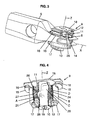
- the outer surface of the frame 10 comprises, in correspondence with the two arms 12 of the body in elastomer, two wedge-shaped support zones 20 which protrude radially outward and which converge down towards the central axis Z (see figures 4 and 6).
- the elastomer body 11 for its part, is molded and adhered to the outer surface of the frame interior 10, and extends radially outward up to an intermediate annular reinforcement 21 which is present for example in the form of a sheet metal ring cut and stamped, clearly visible in Figure 9.
- This intermediate frame 21 has two continuous annular bearings 22, 23, respectively upper and lower, which are interconnected by two support zones 24 stamped inwards, delimiting with the annular spans 22, 23 two windows open 25.
- the elastomer body 5 has two cavities arranged in correspondence with windows 25 of the intermediate frame between the arms 12. These cavities delimit with the external frame 8 two chambers hydraulic A, B filled with liquid, which are closed tightly sealed by radial tightening of the external frame 8 on the annular bearings 22, 23 of the armature intermediate 21, the outer frame 8 being further secured axially to the intermediate frame 21 by legs 26 of said outer frame which are crimped against the axial ends of the frame intermediate 21.
- each of hydraulic chambers A, B can advantageously receive a insert 27 made for example of plastic material substantially rigid and adapted to cooperate by abutment with a boss 28 projecting radially outwards from the internal frame 10 in the room corresponding hydraulic A, B.
- the two hydraulic chambers A, B communicate between them via a strangled passage C which can advantageously be delimited between the frame exterior 8 and a circumferential groove formed in a elastomeric bead 29 which extends circumferentially in the lower and outer part of one of the zones support 24 of the intermediate frame 21, called the first support zone 24.
- Said first support zone 24 of the armature intermediate 21 further delimits with the reinforcement outer 8, above the elastomer bead 29, a first liquid conduit D which communicates on the one hand with the hydraulic chamber A and on the other hand with the chamber hydraulic B.
- This first liquid conduit D is closed by an axial rib 30 made of elastomer, of relatively thin, which extends parallel to the Z axis and radially outward, to an outer edge in waterproof support against the inside surface of the frame 8.
- This rib 30 is flexible enough to form a decoupling valve, which, given the relatively large passage section of the first duct of liquid D (in practice, at least three times greater than the section of the strangled passage C), makes it possible to transmit directly from one hydraulic chamber to another relatively small amplitude vibrations (for example, less than 1 mm) and relatively high frequency (for example, between 5 and 50 Hz), which allows filter these vibrations of small amplitude and large frequency without transmitting them from one frame to another.
- relatively small amplitude vibrations for example, less than 1 mm
- relatively high frequency for example, between 5 and 50 Hz
- the second support zone 24 of the intermediate frame 21 delimits with the frame exterior 8 a second liquid conduit E which is closed by an axial rib 31 extending parallel to the Z axis and radially outward to an edge external in leaktight contact with the external frame 8.
- This second axial rib 31 also forms a valve. decoupling, in the same way as the rib 30 above.
Landscapes
- Engineering & Computer Science (AREA)
- General Engineering & Computer Science (AREA)
- Mechanical Engineering (AREA)
- Combined Devices Of Dampers And Springs (AREA)
- Vehicle Body Suspensions (AREA)
- Vibration Prevention Devices (AREA)
- Lift-Guide Devices, And Elevator Ropes And Cables (AREA)
Applications Claiming Priority (2)
| Application Number | Priority Date | Filing Date | Title |
|---|---|---|---|
| FR0016924A FR2818718B1 (fr) | 2000-12-22 | 2000-12-22 | Manchon antivibratoire et vehicule automobile comportant un tel manchon |
| FR0016924 | 2000-12-22 |
Publications (2)
| Publication Number | Publication Date |
|---|---|
| EP1217249A1 true EP1217249A1 (de) | 2002-06-26 |
| EP1217249B1 EP1217249B1 (de) | 2005-05-04 |
Family
ID=8858113
Family Applications (1)
| Application Number | Title | Priority Date | Filing Date |
|---|---|---|---|
| EP01403254A Expired - Lifetime EP1217249B1 (de) | 2000-12-22 | 2001-12-14 | Schwingungsdämpfendes Lager und Kraftfahrzeug mit einem solchen Lager |
Country Status (7)
| Country | Link |
|---|---|
| US (1) | US6729611B2 (de) |
| EP (1) | EP1217249B1 (de) |
| JP (1) | JP4040872B2 (de) |
| BR (1) | BR0106240A (de) |
| DE (1) | DE60110534T2 (de) |
| ES (1) | ES2240376T3 (de) |
| FR (1) | FR2818718B1 (de) |
Cited By (7)
| Publication number | Priority date | Publication date | Assignee | Title |
|---|---|---|---|---|
| WO2004088165A1 (de) | 2003-04-03 | 2004-10-14 | Trelleborg Automotive Technical Centre Gmbh | Lagerbuchse mit federelement |
| WO2005035284A2 (fr) * | 2003-10-10 | 2005-04-21 | Renault S.A.S | Essieu directeur d'un vehicule automobile |
| DE102009031846A1 (de) * | 2009-07-03 | 2011-01-05 | GM Global Technology Operations, Inc., Detroit | Hinterachse vom Verbundlenkerachstyp für Kraftfahrzeug |
| EP2463544A1 (de) * | 2010-12-09 | 2012-06-13 | Toyo Tire & Rubber Co., Ltd. | Schwingungsdämpfungsvorrichtung |
| CN102562893A (zh) * | 2010-12-09 | 2012-07-11 | 东洋橡胶工业株式会社 | 防振装置 |
| WO2014161702A1 (de) * | 2013-03-30 | 2014-10-09 | Volkswagen Aktiengesellschaft | Achsführungslager zur ankopplung einer hinterachse an einen fahrzeugaufbau eines kraftfahrzeugs |
| US11433725B2 (en) * | 2018-10-04 | 2022-09-06 | Mazda Motor Corporation | Bushing and vehicle suspension device |
Families Citing this family (18)
| Publication number | Priority date | Publication date | Assignee | Title |
|---|---|---|---|---|
| DE10040201B4 (de) * | 2000-08-17 | 2005-06-30 | Trelleborg Automotive Technical Centre Gmbh | Hydraulisch dämpfendes Lager |
| WO2004083675A1 (ja) * | 2003-03-19 | 2004-09-30 | Toyo Tire & Rubber Co., Ltd. | 防振装置及び防振装置の製造方法 |
| JP4107610B2 (ja) * | 2003-04-14 | 2008-06-25 | 東洋ゴム工業株式会社 | 防振装置 |
| JP2004353786A (ja) * | 2003-05-29 | 2004-12-16 | Favess Co Ltd | 弾性支持構造およびこれを用いるパワーステアリング装置 |
| DE102007036576A1 (de) | 2007-08-02 | 2009-02-05 | Carl Freudenberg Kg | Gummilager |
| US7914023B2 (en) * | 2009-03-13 | 2011-03-29 | GM Global Technology Operations LLC | Parallelogram-style steering mechanism having a relay rod bushing |
| JP5595203B2 (ja) * | 2010-09-29 | 2014-09-24 | 東海ゴム工業株式会社 | トーコレクトブッシュ |
| JP5473884B2 (ja) * | 2010-12-09 | 2014-04-16 | 東洋ゴム工業株式会社 | 防振装置 |
| DE102011008625A1 (de) * | 2011-01-14 | 2012-07-19 | Audi Ag | Feder- und Dämpfersystem, insbesondere für eine Aggregatelagerung in einem Kraftfahrzeug |
| DE102012200001A1 (de) * | 2012-01-02 | 2013-07-04 | Ford Global Technologies, Llc | Gummimetallager für Kraftfahrzeug-Radaufhängung, Trapezlenker und Radaufhängung |
| JP6002607B2 (ja) * | 2013-03-12 | 2016-10-05 | 住友理工株式会社 | 防振装置 |
| JP5753225B2 (ja) * | 2013-06-17 | 2015-07-22 | 住友理工株式会社 | 防振装置 |
| KR102083206B1 (ko) * | 2013-10-25 | 2020-03-02 | 현대모비스 주식회사 | 부시 조립장치 |
| DE102014201057A1 (de) * | 2014-01-22 | 2015-07-23 | Zf Friedrichshafen Ag | Bauteilanbindung mit querkraftabstützender Stützfläche |
| US10603970B2 (en) * | 2015-12-15 | 2020-03-31 | Anand Nvh Products Inc. | Bushing for vehicle suspension system |
| DE102017106289B4 (de) * | 2017-03-23 | 2019-09-12 | Vibracoustic Gmbh | Lagerbuchse |
| EP3781834A1 (de) * | 2018-04-17 | 2021-02-24 | Cooper Standard France | Gelenkelement zur filterung und dämpfung von schwingungen und gelenkvorrichtung |
| KR20230024601A (ko) * | 2021-08-12 | 2023-02-21 | 현대자동차주식회사 | Ctba 부시 |
Citations (9)
| Publication number | Priority date | Publication date | Assignee | Title |
|---|---|---|---|---|
| FR2434965A1 (fr) * | 1978-09-02 | 1980-03-28 | Volkswagenwerk Ag | Support de metal sur caoutchouc, en particulier pour articulation a oscillations d'un bras oscillant de guidage de roue ou d'un essieu a bras oscillants jumeles sur la carrosserie d'un vehicule automobile |
| DE3240981A1 (de) * | 1982-11-05 | 1984-05-10 | Bayerische Motoren Werke AG, 8000 München | Gummi-metall-lager |
| DE3441560A1 (de) | 1984-11-14 | 1986-05-22 | Adam Opel AG, 6090 Rüsselsheim | Hinterachse |
| FR2717236A1 (fr) * | 1994-03-11 | 1995-09-15 | Hutchinson | Articulation élastique. |
| EP0687830A1 (de) * | 1994-06-15 | 1995-12-20 | Hutchinson | Elastisches Kippgelenk, insbesondere für eine Einarmschwinge von Rädern |
| US5655758A (en) * | 1995-03-28 | 1997-08-12 | Toyoda Gosei Co., Ltd. | Bushing for vehicle suspension |
| JPH10339349A (ja) * | 1997-04-08 | 1998-12-22 | Yamashita Rubber Kk | 液封ブッシュ |
| FR2791002A1 (fr) * | 1999-03-16 | 2000-09-22 | Peugeot Citroen Automobiles Sa | Train arriere autobraqueur pour vehicule automobile |
| GB2351139A (en) * | 1999-06-14 | 2000-12-20 | Avon Vibration Man Syst Ltd | Mounting device for hydraulically damping both axial and radial vibrations |
Family Cites Families (19)
| Publication number | Priority date | Publication date | Assignee | Title |
|---|---|---|---|---|
| DE1780687B2 (de) | 1966-11-11 | 1976-06-24 | Ausscheidung aus: 15 55 163 Daimler-Benz AG, 7000 Stuttgart | Elastische lagerung eines tragkoerpers zur hinterachsaufhaengung eines kraftfahrzeuges |
| DE2748193A1 (de) | 1977-10-27 | 1979-05-03 | Volkswagenwerk Ag | Gummimetall-lager, insbesondere fuer die schwenkbare anlenkung eines fuehrungslenkers oder eines achsverbundes am aufbau eines kraftfahrzeuges |
| JPS56119031U (de) * | 1980-02-05 | 1981-09-10 | ||
| DE3346665A1 (de) * | 1983-12-23 | 1985-07-04 | Lemförder Metallwaren AG, 2844 Lemförde | Elastisches lager mit zwangsfuehrung |
| DE3521361A1 (de) | 1984-07-10 | 1986-01-23 | Volkswagenwerk Ag, 3180 Wolfsburg | Verbund- oder koppellenker-hinterachse fuer kraftfahrzeuge |
| DE3707162A1 (de) * | 1986-03-11 | 1987-10-01 | Mazda Motor | Hinterradaufhaengung fuer fahrzeuge |
| FR2649364B1 (fr) | 1989-07-07 | 1994-03-18 | Renault Regie Nale Usines | Train arriere de vehicule automobile |
| FR2675869B1 (fr) * | 1991-04-23 | 1993-08-13 | Hutchinson | Perfectionnements aux manchons antivibratoires hydrauliques. |
| JPH0512779U (ja) * | 1991-07-30 | 1993-02-19 | 東海ゴム工業株式会社 | ブツシユ |
| US5246248A (en) * | 1992-05-15 | 1993-09-21 | General Motors Corporation | Vehicle rear suspension apparatus |
| JPH08105477A (ja) * | 1994-10-04 | 1996-04-23 | Bridgestone Corp | 防振装置 |
| JPH08177954A (ja) * | 1994-12-21 | 1996-07-12 | Tokai Rubber Ind Ltd | 流体封入式筒型防振装置 |
| JPH08177917A (ja) * | 1994-12-27 | 1996-07-12 | Tokai Rubber Ind Ltd | 筒型防振マウント |
| FR2730537B1 (fr) * | 1995-02-13 | 1997-04-25 | Hutchinson | Manchon antivibratoire hydraulique et son procede de fabrication |
| FR2730973B1 (fr) | 1995-02-28 | 1997-05-16 | Peugeot | Articulation elastique notamment pour un train roulant de vehicule automobile |
| US5842687A (en) * | 1997-04-25 | 1998-12-01 | Lord Corporation | Self-aligning vibration mount with compound-angled flexing elements |
| FR2769060B1 (fr) | 1997-09-26 | 2000-10-13 | Peugeot | Articulation elastique, notamment pour un train roulant de vehicule automobile |
| JPH11241748A (ja) * | 1998-02-26 | 1999-09-07 | Tokai Rubber Ind Ltd | 流体封入式筒型マウント |
| JP2001132785A (ja) * | 1999-11-02 | 2001-05-18 | Nissan Motor Co Ltd | 防振装置 |
-
2000
- 2000-12-22 FR FR0016924A patent/FR2818718B1/fr not_active Expired - Lifetime
-
2001
- 2001-12-14 DE DE60110534T patent/DE60110534T2/de not_active Expired - Lifetime
- 2001-12-14 ES ES01403254T patent/ES2240376T3/es not_active Expired - Lifetime
- 2001-12-14 EP EP01403254A patent/EP1217249B1/de not_active Expired - Lifetime
- 2001-12-20 US US10/033,819 patent/US6729611B2/en not_active Expired - Lifetime
- 2001-12-21 BR BR0106240-9A patent/BR0106240A/pt active Search and Examination
- 2001-12-25 JP JP2001392117A patent/JP4040872B2/ja not_active Expired - Fee Related
Patent Citations (9)
| Publication number | Priority date | Publication date | Assignee | Title |
|---|---|---|---|---|
| FR2434965A1 (fr) * | 1978-09-02 | 1980-03-28 | Volkswagenwerk Ag | Support de metal sur caoutchouc, en particulier pour articulation a oscillations d'un bras oscillant de guidage de roue ou d'un essieu a bras oscillants jumeles sur la carrosserie d'un vehicule automobile |
| DE3240981A1 (de) * | 1982-11-05 | 1984-05-10 | Bayerische Motoren Werke AG, 8000 München | Gummi-metall-lager |
| DE3441560A1 (de) | 1984-11-14 | 1986-05-22 | Adam Opel AG, 6090 Rüsselsheim | Hinterachse |
| FR2717236A1 (fr) * | 1994-03-11 | 1995-09-15 | Hutchinson | Articulation élastique. |
| EP0687830A1 (de) * | 1994-06-15 | 1995-12-20 | Hutchinson | Elastisches Kippgelenk, insbesondere für eine Einarmschwinge von Rädern |
| US5655758A (en) * | 1995-03-28 | 1997-08-12 | Toyoda Gosei Co., Ltd. | Bushing for vehicle suspension |
| JPH10339349A (ja) * | 1997-04-08 | 1998-12-22 | Yamashita Rubber Kk | 液封ブッシュ |
| FR2791002A1 (fr) * | 1999-03-16 | 2000-09-22 | Peugeot Citroen Automobiles Sa | Train arriere autobraqueur pour vehicule automobile |
| GB2351139A (en) * | 1999-06-14 | 2000-12-20 | Avon Vibration Man Syst Ltd | Mounting device for hydraulically damping both axial and radial vibrations |
Non-Patent Citations (1)
| Title |
|---|
| PATENT ABSTRACTS OF JAPAN vol. 1999, no. 03 31 March 1999 (1999-03-31) * |
Cited By (13)
| Publication number | Priority date | Publication date | Assignee | Title |
|---|---|---|---|---|
| WO2004088165A1 (de) | 2003-04-03 | 2004-10-14 | Trelleborg Automotive Technical Centre Gmbh | Lagerbuchse mit federelement |
| DE10315247A1 (de) * | 2003-04-03 | 2004-10-21 | Trelleborg Automotive Technical Centre Gmbh | Lagerbuchse mit Federelement |
| DE10315247B4 (de) * | 2003-04-03 | 2005-05-25 | Trelleborg Automotive Technical Centre Gmbh | Lagerbuchse mit Federelement |
| WO2005035284A2 (fr) * | 2003-10-10 | 2005-04-21 | Renault S.A.S | Essieu directeur d'un vehicule automobile |
| WO2005035284A3 (fr) * | 2003-10-10 | 2005-06-23 | Renault Sa | Essieu directeur d'un vehicule automobile |
| DE102009031846A1 (de) * | 2009-07-03 | 2011-01-05 | GM Global Technology Operations, Inc., Detroit | Hinterachse vom Verbundlenkerachstyp für Kraftfahrzeug |
| EP2463544A1 (de) * | 2010-12-09 | 2012-06-13 | Toyo Tire & Rubber Co., Ltd. | Schwingungsdämpfungsvorrichtung |
| CN102562894A (zh) * | 2010-12-09 | 2012-07-11 | 东洋橡胶工业株式会社 | 防振装置 |
| CN102562893A (zh) * | 2010-12-09 | 2012-07-11 | 东洋橡胶工业株式会社 | 防振装置 |
| WO2014161702A1 (de) * | 2013-03-30 | 2014-10-09 | Volkswagen Aktiengesellschaft | Achsführungslager zur ankopplung einer hinterachse an einen fahrzeugaufbau eines kraftfahrzeugs |
| CN105102246A (zh) * | 2013-03-30 | 2015-11-25 | 大众汽车有限公司 | 用于将后桥耦连在机动车的车辆结构上的车桥导向轴承 |
| CN105102246B (zh) * | 2013-03-30 | 2017-10-10 | 大众汽车有限公司 | 用于将后桥耦连在机动车的车辆结构上的车桥导向轴承 |
| US11433725B2 (en) * | 2018-10-04 | 2022-09-06 | Mazda Motor Corporation | Bushing and vehicle suspension device |
Also Published As
| Publication number | Publication date |
|---|---|
| US6729611B2 (en) | 2004-05-04 |
| JP2002254911A (ja) | 2002-09-11 |
| FR2818718A1 (fr) | 2002-06-28 |
| DE60110534D1 (de) | 2005-06-09 |
| EP1217249B1 (de) | 2005-05-04 |
| JP4040872B2 (ja) | 2008-01-30 |
| ES2240376T3 (es) | 2005-10-16 |
| FR2818718B1 (fr) | 2003-07-25 |
| DE60110534T2 (de) | 2006-02-23 |
| BR0106240A (pt) | 2002-08-20 |
| US20020093170A1 (en) | 2002-07-18 |
Similar Documents
| Publication | Publication Date | Title |
|---|---|---|
| EP1217249B1 (de) | Schwingungsdämpfendes Lager und Kraftfahrzeug mit einem solchen Lager | |
| EP1436524B1 (de) | Hydroelastisches kugelgelenk | |
| FR2896842A1 (fr) | Support antivibratoire hydraulique et son procede de fabrication | |
| EP0735294A1 (de) | Elastisches Gelenk, insbesondere für eine Kraftfahrzeugachse | |
| FR2812241A1 (fr) | Articulation elastique a raideur radiale variable | |
| EP0359655B1 (de) | Hydraulisch gedämpfte Lagerbuchsen | |
| EP2266829B1 (de) | Schwingungsdämpfungsvorrichtung mit begrenztem Hub | |
| EP1283376B1 (de) | Hydraulisches Antischwingungslager | |
| EP2282076B1 (de) | Schwingungsdämpfervorrichtung für ein Fahrzeug, und eine solche Vorrichtung umfassendes Fahrzeug | |
| EP0894995B1 (de) | Schwingungsdämpfendes Lager | |
| EP1489335B1 (de) | Hydraulisches, schwingungsdämpfendes Lager | |
| EP0800017B1 (de) | Hydraulisches, schwingungsdämpfendes Lager und Kraftfahrzeug-Unterbaugruppe mit einem solchen Lager | |
| EP1043514B1 (de) | Drehmomentanlaufsdämpfungsvorrichtung | |
| EP3423733B1 (de) | Schwingungsdämpfungsvorrichtung zwischen einem ersten schwingungselement und einem zweiten element | |
| EP1439320B1 (de) | Schwingungsisolierendes Lager | |
| EP1348611B1 (de) | Halterung für schwenkbare Kraftfahrzeug-Radaufhängung | |
| EP1018448B1 (de) | Vorrichtung zur Aufhängung einer Antriebseinheit am Kraftfahrzeugaufbau | |
| EP1293701B1 (de) | Schwingungsdämpfendes Lager und Schwingungsdämpfungseinrichtung mit solchem Lager | |
| FR2794503A1 (fr) | Bielle antivibratoire | |
| EP1067309B1 (de) | Hydroelastisches Lager für die Antriebseinheit in einem Kraftfahrzeug | |
| EP0845617B1 (de) | Schwingungsdämpfendes Lager und Kraftfahrzeug mit solchem Lager | |
| FR2739669A1 (fr) | Support antivibratoire hydraulique | |
| EP4313651A1 (de) | Aufhängevorrichtung für abgasleitungen eines fahrzeugs | |
| FR2796114A1 (fr) | Support hydroelastique pour la suspension d'un groupe motopropulseur dans un vehicule automobile | |
| FR2876430A1 (fr) | Dispositif anti-vibratoire hydraulique et son procede de fabrication |
Legal Events
| Date | Code | Title | Description |
|---|---|---|---|
| PUAI | Public reference made under article 153(3) epc to a published international application that has entered the european phase |
Free format text: ORIGINAL CODE: 0009012 |
|
| AK | Designated contracting states |
Kind code of ref document: A1 Designated state(s): AT BE CH CY DE DK ES FI FR GB GR IE IT LI LU MC NL PT SE TR |
|
| AX | Request for extension of the european patent |
Free format text: AL;LT;LV;MK;RO;SI |
|
| 17P | Request for examination filed |
Effective date: 20020803 |
|
| AKX | Designation fees paid |
Designated state(s): DE ES GB IT |
|
| GRAP | Despatch of communication of intention to grant a patent |
Free format text: ORIGINAL CODE: EPIDOSNIGR1 |
|
| GRAS | Grant fee paid |
Free format text: ORIGINAL CODE: EPIDOSNIGR3 |
|
| GRAA | (expected) grant |
Free format text: ORIGINAL CODE: 0009210 |
|
| AK | Designated contracting states |
Kind code of ref document: B1 Designated state(s): DE ES GB IT |
|
| PG25 | Lapsed in a contracting state [announced via postgrant information from national office to epo] |
Ref country code: GB Free format text: LAPSE BECAUSE OF FAILURE TO SUBMIT A TRANSLATION OF THE DESCRIPTION OR TO PAY THE FEE WITHIN THE PRESCRIBED TIME-LIMIT Effective date: 20050504 |
|
| REG | Reference to a national code |
Ref country code: GB Ref legal event code: FG4D Free format text: NOT ENGLISH |
|
| REG | Reference to a national code |
Ref country code: IE Ref legal event code: FG4D Free format text: LANGUAGE OF EP DOCUMENT: FRENCH |
|
| REF | Corresponds to: |
Ref document number: 60110534 Country of ref document: DE Date of ref document: 20050609 Kind code of ref document: P |
|
| REG | Reference to a national code |
Ref country code: ES Ref legal event code: FG2A Ref document number: 2240376 Country of ref document: ES Kind code of ref document: T3 |
|
| GBV | Gb: ep patent (uk) treated as always having been void in accordance with gb section 77(7)/1977 [no translation filed] |
Effective date: 20050504 |
|
| PLBE | No opposition filed within time limit |
Free format text: ORIGINAL CODE: 0009261 |
|
| STAA | Information on the status of an ep patent application or granted ep patent |
Free format text: STATUS: NO OPPOSITION FILED WITHIN TIME LIMIT |
|
| 26N | No opposition filed |
Effective date: 20060207 |
|
| PGFP | Annual fee paid to national office [announced via postgrant information from national office to epo] |
Ref country code: DE Payment date: 20191216 Year of fee payment: 19 |
|
| PGFP | Annual fee paid to national office [announced via postgrant information from national office to epo] |
Ref country code: IT Payment date: 20191216 Year of fee payment: 19 |
|
| PGFP | Annual fee paid to national office [announced via postgrant information from national office to epo] |
Ref country code: ES Payment date: 20200124 Year of fee payment: 19 |
|
| REG | Reference to a national code |
Ref country code: DE Ref legal event code: R119 Ref document number: 60110534 Country of ref document: DE |
|
| PG25 | Lapsed in a contracting state [announced via postgrant information from national office to epo] |
Ref country code: IT Free format text: LAPSE BECAUSE OF NON-PAYMENT OF DUE FEES Effective date: 20201214 |
|
| PG25 | Lapsed in a contracting state [announced via postgrant information from national office to epo] |
Ref country code: DE Free format text: LAPSE BECAUSE OF NON-PAYMENT OF DUE FEES Effective date: 20210701 |
|
| REG | Reference to a national code |
Ref country code: ES Ref legal event code: FD2A Effective date: 20220214 |
|
| PG25 | Lapsed in a contracting state [announced via postgrant information from national office to epo] |
Ref country code: ES Free format text: LAPSE BECAUSE OF NON-PAYMENT OF DUE FEES Effective date: 20201215 |