EP3423733B1 - Schwingungsdämpfungsvorrichtung zwischen einem ersten schwingungselement und einem zweiten element - Google Patents
Schwingungsdämpfungsvorrichtung zwischen einem ersten schwingungselement und einem zweiten element Download PDFInfo
- Publication number
- EP3423733B1 EP3423733B1 EP17704500.2A EP17704500A EP3423733B1 EP 3423733 B1 EP3423733 B1 EP 3423733B1 EP 17704500 A EP17704500 A EP 17704500A EP 3423733 B1 EP3423733 B1 EP 3423733B1
- Authority
- EP
- European Patent Office
- Prior art keywords
- opening
- framework
- orientation
- frame
- head
- Prior art date
- Legal status (The legal status is an assumption and is not a legal conclusion. Google has not performed a legal analysis and makes no representation as to the accuracy of the status listed.)
- Active
Links
- 238000013016 damping Methods 0.000 title claims description 23
- 229920001971 elastomer Polymers 0.000 claims description 12
- 239000000806 elastomer Substances 0.000 claims description 12
- 238000006073 displacement reaction Methods 0.000 claims description 5
- 230000001174 ascending effect Effects 0.000 claims description 3
- 230000014759 maintenance of location Effects 0.000 claims description 3
- 208000031968 Cadaver Diseases 0.000 description 4
- 239000002184 metal Substances 0.000 description 4
- 230000006835 compression Effects 0.000 description 1
- 238000007906 compression Methods 0.000 description 1
- 238000001914 filtration Methods 0.000 description 1
- 238000012423 maintenance Methods 0.000 description 1
- 238000004519 manufacturing process Methods 0.000 description 1
- 238000000034 method Methods 0.000 description 1
- 230000002787 reinforcement Effects 0.000 description 1
Images


Classifications
-
- F—MECHANICAL ENGINEERING; LIGHTING; HEATING; WEAPONS; BLASTING
- F16—ENGINEERING ELEMENTS AND UNITS; GENERAL MEASURES FOR PRODUCING AND MAINTAINING EFFECTIVE FUNCTIONING OF MACHINES OR INSTALLATIONS; THERMAL INSULATION IN GENERAL
- F16F—SPRINGS; SHOCK-ABSORBERS; MEANS FOR DAMPING VIBRATION
- F16F1/00—Springs
- F16F1/36—Springs made of rubber or other material having high internal friction, e.g. thermoplastic elastomers
- F16F1/373—Springs made of rubber or other material having high internal friction, e.g. thermoplastic elastomers characterised by having a particular shape
-
- F—MECHANICAL ENGINEERING; LIGHTING; HEATING; WEAPONS; BLASTING
- F16—ENGINEERING ELEMENTS AND UNITS; GENERAL MEASURES FOR PRODUCING AND MAINTAINING EFFECTIVE FUNCTIONING OF MACHINES OR INSTALLATIONS; THERMAL INSULATION IN GENERAL
- F16F—SPRINGS; SHOCK-ABSORBERS; MEANS FOR DAMPING VIBRATION
- F16F1/00—Springs
- F16F1/36—Springs made of rubber or other material having high internal friction, e.g. thermoplastic elastomers
- F16F1/38—Springs made of rubber or other material having high internal friction, e.g. thermoplastic elastomers with a sleeve of elastic material between a rigid outer sleeve and a rigid inner sleeve or pin, i.e. bushing-type
- F16F1/3842—Method of assembly, production or treatment; Mounting thereof
- F16F1/3849—Mounting brackets therefor, e.g. stamped steel brackets; Restraining links
Definitions
- the invention relates to a device for damping vibrations between a first vibrating element and a second element.
- the field of application of the invention can be any vibrating element, such as for example an engine, to be fixed to a frame, such as for example to the body of a motor vehicle.
- a vibrating element such as for example an engine
- US2012267184 discloses the features of the preamble of claim 1.
- This known device has the drawback due to the fact that the elastomeric body requires the presence of a metal cup overmolded in the lower part of this elastomeric body in order to maintain it in the lower part of the outer frame.
- the elastomeric body cooperates, via an overmolded lower cup, with the outer frame in a zone substantially flush with a face opposite the passage, namely against a side member forming part of the motor vehicle and closing the casing against the first rigid element fixed to the engine.
- the damping is therefore effected by the elastomer body bonded against a cup itself placed against the open face of the box located near the spar.
- the invention aims to obtain a device for damping vibrations between a first vibrating element and a second element, making it possible to limit the movements in the 2 directions of the 3 vertical, transverse and longitudinal directions, advantageously not requiring the presence of a any cup in the lower part of the elastomeric body and ensuring maintenance of the elastomeric body in the lower part of an outer frame.
- the upper part (41) comprises a protuberance (415) abutting in the upper part of the first opening (32) on a surface arranged on the element (E2), this protuberance damping and limiting the following displacement the first sense (t2).
- the base (42) of the elastomeric body (4) is connected in a vertical direction (v1) to a vertical extension (43), the frame (3) comprising a third surface (39) in which is arranged a second opening (38) extending around the vertical direction (V) and being, in the transverse direction (T) and a longitudinal horizontal direction ( L), wider than the extension (43), the second opening (36) being crossed by the extension 1 (43), the frame (3) having at least a fourth surface (381), which is located opposite the transverse extension (43) in the first direction (t2).
- a removable pin (5) is inserted in the direction (V) in a hole (431) of the extension (43) and is fitted into a hole (221) of the head (22) to become integral with the head (22), this pin (5) extends into the third opening (38) of the frame (3).
- the extension (43) dampens and limits the movement of the element (2) in the first direction (t2) by coming into contact with the fourth surface (381) of the reinforcement (3).
- the extension (43) dampens and limits the movements in the directions (t1) (l1) (l2) in the same way as the direction (t2).
- the frame (3) to have an outline (37) delimiting a third opening (31), the opening (31) extending around the transverse direction (T) and being, in the directions (V) and (L), wider than the arm (21) so that the frame (3) surrounds the arm ( 21) at this opening (31), the opening (31) being narrower than the head (22) in direction V, the frame (3) having a contour (36) delimiting the first opening (32), the first opening (32) extending around the transverse direction (T) and being, in the directions (V) and (L), wider than the head (22), to allow the passage of the limb (2) to the through the first opening (32).
- the elastomeric body (4) is overmolded on the head (22) of the member (2) and is inserted into the frame (3).
- the frame (3) comprises at least a first leg (33) and at least a second leg (34), for example of inclined oblong shapes, which extend in the direction (t1) opposite of the first opening (32) and which are positioned projecting from a surface (35) of the frame (3).
- the elastomeric body (4) comprising an upper part (41) overmolded around the head (22) and a lower part (42), hereinafter called the base, having the function of fixing to the frame (3), the base (42) extending the upper part (41) in the vertical direction (v1), the base (42) comprising at least one first hole (421) and at least one second hole (422) , in which are respectively fitted the first tab (33) and the second tab (34) for fixing the elastomeric body (4) to the frame (3).
- the base (42) supports the load and dampens vibrations under low forces in the directions (V) (L) and (T).
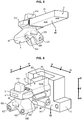
- the invention is described with reference to three orthonormal directions L, T and V of space, namely a horizontal longitudinal direction L, a horizontal transverse direction T and a vertical direction V.
- the elastomeric body 4 is fixed to the frame 3 in a zone located away from the opening 31 for passage of the member 2 in the frame 3 and at a distance from the second opening 32 serving for the passage of the head 22 of member 2, as will be described below.
- the member 2 is rigid and is for example metallic.
- the frame 3 is rigid and for example metallic.
- the vibration damping device 1 is intended to be mounted between a first element E1 and a second element E2.
- the device 1 comprises the member 2 intended to be fixed to the first vibrating element E1.
- the member 2 comprises an arm 21 extending in the direction transverse T.
- the arm 21 is intended to be fixed to the first vibrating element E1.
- the member 2 also comprises a head 22, which extends the arm 21 in a first direction t2 of the transverse direction T and which is wider than the arm 21 in the vertical direction V.
- the device 1 comprises the frame 3 intended to be fixed to the second element E2.
- the first vibrating element E1 is an element capable of emitting mechanical vibrations, when it is put into operation and when the device 1 is in the mounted state.
- the mounted state of device 1 is understood to mean when both the first element E1 is fixed to the member 2 and the frame 3 is fixed to the second element E2.
- the first vibrating element E1 can be for example an engine of a motor vehicle, while the second element E2 can be a body of a motor vehicle.
- the device may include first means for fixing the frame 3 to the second element E2.
- the frame 3 has a generally open shape, having two openings 31 and 32 providing a passage in the transverse direction T.
- the opening 32 being open in its upper part. Below, the opening 32 is called the first opening 32, the opening 31 is called the third opening 31 and the opening 38 is called the second opening 38.
- the frame 3 comprises a surface 37 delimiting the opening 31.
- the opening 31 extends around the transverse direction T. This opening 31 is wider than the arm 21 and less wide than the head 22. Thus, the frame 3 surrounds the arm 21 at the level of this first opening 31 and retains the head 22.
- the frame 3 comprises a contour 36 defining the opening 32.
- the opening 32 extends around the transverse direction T.
- the second opening 32 allows the passage of the member 2 to pass, during assembly. of the device 1 on the motor vehicle, the member 2 of the disassembled state of the figure 6 or 9 , in which the base 42 is at a distance from the frame 3, in the mounted state of the figures 1, 2 and 3 or 8 , where the member 2 passes through the opening 31 and the elastomeric body 4 is fixed by its base 42 to the frame 3.
- the elastomeric body 4 is fixed to at least one outer surface of the member 2.
- the elastomeric body 4 East turned towards the frame 3 in the mounted state of the device 1. This elastomeric body 4 is linked to the head 22.
- the frame 3 comprises a surface 35 moving away from the first opening 31 starting from the surface 37 delimiting the opening 31.
- the surface 35 extends at least in the second direction v1 (downward vertical ) in the vertical direction V.
- the frame 3 comprises at least a first lug 33 and at least a second lug 34, which extend in the first direction t2 opposite the second opening 32 and which are positioned projecting starting from surface 35.
- the elastomeric body 4 comprises an upper part 41 molded around the head 22.
- the elastomeric body 4 also comprises the base 42 having the function of fixing the elastomeric body 4 to the frame 3.
- the base 42 extends the base. intermediate part 41 in the vertical direction v1 descending.
- the base 42 comprises at least a first hole 421 and at least a second hole 422, which extend in the transverse direction T and through which are respectively force-fitted the first tab 33 and the second tab 34 for fixing the body. 4 made of elastomer to the frame 3.
- the first and second holes 421 and 422 may have, in the disassembled state of the member 2, a first dimension smaller than a second dimension parallel to the first dimension of the first and second tabs 33 and 34, these dimensions being taken in a plane perpendicular to the transverse direction T.
- the first and second tabs 33 and 34 are inserted into the first and second holes 421 and 422, respectively, the The elastomer of the base 42 around the first and second holes 421 and 422 is compressed by the first and second legs 33 and 34, securing the base 42 to the first and second legs 33 and 34.
- the first st and second holes 421 and 422 are through.
- the first and second holes 421 and 422 could be blind.
- each tab 33, 34 may for example be of rounded shape, for example oval or circular, or the like, around the longitudinal direction L, while being able to be cylindrical around the transverse direction T.
- the base 42 comprises two thick legs 425 and 426, located below the head 22 in the first vertical direction v1 and which serves to stiffen the base 42 and the elastomeric body 4.
- the leg 425 is the one surrounding the hole 422 and the leg 426 is the one surrounding the hole 421.
- the frame 3 comprises a surface 331 located opposite the first tab 33 and a surface 341 located opposite the second tab 34.
- the surfaces 331 and 341 are connected to the surface 363 and serve to support respectively against the legs 425 and 426. This reinforces the attachment of the elastomeric body 4 to the frame 3, as well as the rigidity of the elastomeric body 4.
- the intervals between the first and second legs 33 and 34 and the surfaces 331 and 341 may have, in the disassembled state of the member 2, a dimension smaller than that of the elastomeric parts of the legs 426 and 425 surrounding the holes 421 and 422 intended to be inserted therein.
- This method of assembly makes it possible to maintain and dampen vibrations while avoiding having to adhere the elastomer body 4 to another metal cup remote from the member 2, which simplifies the manufacture of the device 1 and reduces its cost.
- the elastomeric body 4 comprises a protuberance 414 located opposite and at a distance from a surface 351 of the frame 3 in a second direction t1 of the transverse direction T, opposite to the first direction t2.
- this protuberance 414 is able to abut against the surface 351 in order to damp the vibrations and limit the movements of the elastomeric body 4 in the direction t1.
- the elastomeric body 4 comprises a protuberance 411 located opposite and at a distance from a surface 361 of the frame 3 in a first direction 11 of the horizontal longitudinal direction L.
- this protuberance 411 is able to abut against the surface 361 to damp vibrations and limit the movements of the elastomeric body 4 along the direction 11.
- the elastomeric body 4 comprises a protuberance 412 located opposite and at a distance from a surface 362 of the frame 3 in a second direction l2 of the horizontal longitudinal direction L, opposite to the first direction l1.
- this protuberance 412 is able to abut against the surface 362 in order to damp the vibrations and limit the movements of the elastomeric body 4 in the direction l2.
- the elastomeric body 4 comprises a protuberance 413 located opposite and at a distance from a surface 371 of the frame 3 in an ascending vertical direction v2.
- this protuberance 413 is able to abut against the surface 371 to dampen the vibrations and limit the movements of the elastomeric body 4 in the direction v2.
- the elastomeric body 4 comprises a protuberance 423 located opposite and at a distance from a surface 363 of the frame 3 in a downward vertical direction v1.
- this protuberance 423 is able to abut against the surface 363 in order to dampen the vibrations and limit the movements of the elastomeric body 4 in the direction v1.
- the elastomeric body 4 comprises a protuberance 415 situated opposite and at a distance from a surface previously arranged on the element E2 opposite the upper part of the second opening 32 in the direction t2.
- this protuberance 415 is able to abut against the surface of the element E2 in order to damp the vibrations and limit the movements of the elastomeric body 4 in the direction t2.
- the frame 3 is fixed to a substantially vertical wall of the element E2.
- This wall can be opened or closed in front of the base 42 of the elastomeric body 4.
- the base 42 of the elastomeric body 4 being held by the lugs 33 and 34 and the surfaces 331 and 341, this base 42 therefore does not require any cooperation.
- the frame 3 may include first means 391 for fixing in the horizontal direction t2 for this purpose. These means 391 comprise, for example, through holes 392, 393 for the passage of screws in the direction t2 on two lower parts 394 and 395 projecting longitudinally of the frame 2, on either side of the opening 32.
- the elastomeric body 4 is positioned to abut, in both directions of the three orthonormal directions L, T and V of space, against corresponding surfaces 361, 362, 363, 371, 351 of the frame 3 and a surface previously arranged on the element E2 or on the body of the motor vehicle opposite the upper part of the opening 32 of the frame 3.
- element 1 provides filtration, vibration damping and limitation of deflections in the 2 directions of the 3 directions L, T and V between element E1 and element E2.
- the base 42 is connected in the vertical direction v1 descending to a vertical extension 43.
- the frame 3 comprises an opening 38 passing through in the vertical direction V.
- the opening 38 extends at least in the longitudinal L and transverse direction T and is crossed in the downward vertical direction v1 by the transverse extension 43.
- the frame 3 further has at least one surface 381, which extends from the surface 39 to the opening 32.
- the surface 381 is located opposite the transverse extension 43 in the first direction t2.
- the movement of the elastomeric body 4 in the first longitudinal direction t2 is limited by the surface 381 forming part of the frame 3.
- the second opening 32 can remain open without having to be closed by a wall of the element.
- Extension 43 can be located substantially against the surface 381 in the mounted state, therefore with a substantially zero or very small distance between the surface 381 and the extension 43.
- the device comprises a pin 5, which, in the mounted state, is fixed to the head 22 and which extends into the third opening 38 in the direction v1.
- the pin 5 In the mounted state, the pin 5 is located in the center of the vertical extension 43. This pin 5 makes it possible to strengthen the holding of the extension 43 against the surface 381.
- the extension 43 is located between the first leg 425 and the second leg 426.
- the base 42 thus offers, through the legs 425 and 426, a stable and stiffened seat for the transverse extension 43.
- the pin 5 is a removable part, attached to the head 22 when the transverse extension 43 is inserted into the opening 38.
- the arm 21 is first inserted in the opening 31 by inserting the head 22 through the opening 32 and the base 42 is threaded around the tabs 33 and 34 so as to cause the extension 43 to pass through the opening 38, by deformation of this vertical extension 43.
- the pin 5 is inserted into the head 22 by passing through the opening 38 and the body 4 made of elastomer.
- the vertical extension 43 comprises a hole 431 for passing through the pin 5.
- the head 22 has a hole 221 for inserting the pin 5 into the head 22.
- the frame 3 is fixed to a substantially horizontal wall of the element E2.
- the frame 3 may include second means 391 ′ for fixing in the vertical direction v1 for this purpose.
- These means 391 ′ comprise, for example, through holes 392 ′, 393 ′ for the passage of screws in direction V1 on two lower parts 394 and 395 projecting longitudinally of the frame 2, on either side of the opening 32.
- the base 42 of the elastomeric body 4 being held by the tabs 33 and 34 and the surfaces 331 and 341, this base 42 does not therefore no need to add any additional metal frame to ensure its retention within the element 3.
- the elastomeric body 4 is positioned to abut, in both directions of the three orthonormal directions L, T and V of space, against corresponding surfaces 361, 362, 363, 351, 371 and 381 of the frame 3, thus dispensing with abutting against the second element E2 or against the body of the motor vehicle.
- each characteristic indicated above can be selected independently of the other characteristics or be combined with one or more other characteristics in the device.
Landscapes
- Engineering & Computer Science (AREA)
- General Engineering & Computer Science (AREA)
- Mechanical Engineering (AREA)
- Manufacturing & Machinery (AREA)
- Vibration Prevention Devices (AREA)
- Arrangement Or Mounting Of Propulsion Units For Vehicles (AREA)
- Combined Devices Of Dampers And Springs (AREA)
Claims (5)
- Vorrichtung (1) zur Dämpfung von Vibrationen zwischen einem ersten vibrierenden Element (El) und einem zweiten Element (E2),
wobei die Vorrichtung umfasst:eine Komponente (2), die dafür vorgesehen ist, an dem ersten vibrierenden Element (El) befestigt zu werden, wobei die Komponente (2) einen Arm (21), der sich entlang einer horizontalen Querrichtung (T) erstreckt, und einen Kopf (22) umfasst, welcher den Arm (21) in einem ersten Sinn (t2) der Querrichtung (T) verlängert,einen Anker (3), der dafür vorgesehen ist, an dem zweiten Element (E2) befestigt zu werden,einen Körper (4) aus Elastomer, der an der Komponente (2) befestigt und zu dem Anker (3) gedreht ist,wobei der Anker (3) zumindest eine erste Lasche (33), zumindest ein zweite Lasche (34), zumindest eine erste Oberfläche (331) und zumindest eine zweite Oberfläche (332) umfasst, die sich gegenüber einer ersten Öffnung (32) des Ankers (3) in dem ersten Sinn (t2) erstrecken,wobei der Körper (4) aus Elastomer einen oberen Abschnitt (41) umfasst, der um den Kopf (22) geformt ist, und einen Sockel (42) umfasst, der zumindest zwei Elastomerschenkel (425,426) aufweist, dadurch gekennzeichnet, dass diese Schenkel zumindest zwei Löcher (421,422) aufweisen,wobei der Halt des Sockels (42) des Körpers (4) in dem Anker (3) durch das Aufschieben der Schenkel (425,426) jeweils auf die Laschen (33,34) durch die Löcher (421,422) und das Komprimieren des Elastomers der Schenkel (425,426) jeweils zwischen der ersten und der zweiten Oberfläche (331,332) und der ersten und der zweiten Lasche (33,34) sichergestellt wird, wobei der Kopf in einer vertikalen Richtung (V) breiter als der Arm (21) ist. - Vorrichtung nach Anspruch 1, dadurch gekennzeichnet, dass
der obere Abschnitt (41) Vorsprünge (411,412,413,414,423) aufweist, wobei diese Vorsprünge jeweils gegen andere Oberflächen (361,362,371,351,363) des Ankers (3) stoßen, wobei diese Vorsprünge die Bewegungen zwischen dem Element (El) und dem Element (E2) dämpfen und begrenzen jeweils in:- beiden Sinne (11,12) einer horizontalen Längsrichtung,- einer nach oben gerichteten vertikalen Richtung (v2),- einem zweiten Sinn (t1) der Querrichtung (T), die dem ersten Sinn (t2) entgegengesetzt ist,- einer nach unten gerichteten vertikalen Richtung (v1). - Vorrichtung nach einem der Ansprüche 1 und 2, dadurch gekennzeichnet, dass
der obere Abschnitt (41) einen Vorsprung (415) aufweist, der im oberen Teil der ersten Öffnung (32) gegen eine Fläche stößt, die an dem Element (E2) ausgebildet ist, wobei dieser Vorsprung die Bewegung in dem ersten Sinn (t2) dämpft und begrenzt. - Vorrichtung nach einem der Ansprüche 1 und 2, dadurch gekennzeichnet, dass
der Sockel (42) des Elastomerkörpers (4) in einem vertikalen Sinn (v1) mit einer vertikalen Verlängerung (43) verbunden ist,
wobei der Anker (3) eine dritte Oberfläche (39) aufweist, in der eine zweite Öffnung (38) ausgebildet ist, die sich um die vertikale Richtung (V) erstreckt und entlang der Querrichtung (T) und einer horizontalen Längsrichtung (L) breiter als die Verlängerung (43) ist, wobei die zweite Öffnung (38) von der Verlängerung (43) durchquert wird,
wobei der Anker (3) zumindest eine vierte Fläche (381) aufweist, die gegenüber der vertikalen Verlängerung (43) in dem ersten Sinn (t2) angeordnet ist. - Vorrichtung nach Anspruch 4, dadurch gekennzeichnet, dass
ein herausnehmbarer Stift (5) in der Richtung (V) in eine Bohrung (431) der Verlängerung (43) eingesetzt und in eine Bohrung (221) des Kopfes (22) geschoben wird, um mit dem Kopf (22) fest verbunden zu werden, wobei sich dieser Stift (5) in die dritte Öffnung (38) des Ankers (3) erstreckt,
wobei die Verlängerung (43) die Bewegung der Komponente (2) in dem ersten Sinn (t2) dämpft und begrenzt, indem sie mit der vierten Oberfläche (381) des Ankers (3) in Berührung kommt.
Applications Claiming Priority (2)
| Application Number | Priority Date | Filing Date | Title |
|---|---|---|---|
| FR1651856A FR3048474B1 (fr) | 2016-03-04 | 2016-03-04 | Dispositif d'amortissement de vibrations entre un premier element vibrant et un deuxieme element |
| PCT/EP2017/053458 WO2017148707A1 (fr) | 2016-03-04 | 2017-02-16 | Dispositif d'amortissement de vibrations entre un premier élément vibrant et un deuxième élément |
Publications (2)
| Publication Number | Publication Date |
|---|---|
| EP3423733A1 EP3423733A1 (de) | 2019-01-09 |
| EP3423733B1 true EP3423733B1 (de) | 2021-01-13 |
Family
ID=55808708
Family Applications (1)
| Application Number | Title | Priority Date | Filing Date |
|---|---|---|---|
| EP17704500.2A Active EP3423733B1 (de) | 2016-03-04 | 2017-02-16 | Schwingungsdämpfungsvorrichtung zwischen einem ersten schwingungselement und einem zweiten element |
Country Status (5)
| Country | Link |
|---|---|
| EP (1) | EP3423733B1 (de) |
| CN (1) | CN109073021B (de) |
| BR (1) | BR112018067686A2 (de) |
| FR (1) | FR3048474B1 (de) |
| WO (1) | WO2017148707A1 (de) |
Families Citing this family (2)
| Publication number | Priority date | Publication date | Assignee | Title |
|---|---|---|---|---|
| US10738853B2 (en) * | 2017-08-09 | 2020-08-11 | Vibracoustic Usa, Inc. | Damper and assembly |
| FR3132341A1 (fr) * | 2022-01-31 | 2023-08-04 | Psa Automobiles Sa | Support elastique de groupe motopropulseur de vehicule automobile |
Family Cites Families (9)
| Publication number | Priority date | Publication date | Assignee | Title |
|---|---|---|---|---|
| FR2829208B1 (fr) | 2001-09-05 | 2003-12-05 | Hutchinson | Ensemble anti-vibratoire et support anti-vibratoire faisant partie de cet ensemble |
| DE10249387C5 (de) * | 2002-10-23 | 2008-07-03 | Telleborg Automotive Technical Centre Gmbh | Elastisches Lager, insbesondere zum Abstützen eines Getriebes oder des Motors eines Kraftfahrzeugs |
| US7644911B2 (en) * | 2005-09-22 | 2010-01-12 | The Pullman Company | Isolator |
| JP5297275B2 (ja) * | 2009-06-18 | 2013-09-25 | 東洋ゴム工業株式会社 | 防振装置 |
| DE102010024903A1 (de) * | 2010-06-24 | 2011-12-29 | Anvis Deutschland Gmbh | Vorrichtung zum elastischen Lagern eines Motors und Verfahren zum Herstellen desselben |
| US8403097B2 (en) * | 2011-04-19 | 2013-03-26 | Paulstra Crc | Movement limiting anti-vibration assembly |
| JP2013117259A (ja) * | 2011-12-02 | 2013-06-13 | Bridgestone Corp | 防振装置 |
| JP6190651B2 (ja) * | 2013-07-23 | 2017-08-30 | 住友理工株式会社 | 防振装置 |
| WO2015145672A1 (ja) * | 2014-03-27 | 2015-10-01 | 住友理工株式会社 | 防振装置 |
-
2016
- 2016-03-04 FR FR1651856A patent/FR3048474B1/fr active Active
-
2017
- 2017-02-16 BR BR112018067686A patent/BR112018067686A2/pt not_active Application Discontinuation
- 2017-02-16 EP EP17704500.2A patent/EP3423733B1/de active Active
- 2017-02-16 CN CN201780015166.2A patent/CN109073021B/zh active Active
- 2017-02-16 WO PCT/EP2017/053458 patent/WO2017148707A1/fr active Application Filing
Non-Patent Citations (1)
| Title |
|---|
| None * |
Also Published As
| Publication number | Publication date |
|---|---|
| CN109073021A (zh) | 2018-12-21 |
| FR3048474B1 (fr) | 2018-04-20 |
| BR112018067686A2 (pt) | 2019-01-08 |
| WO2017148707A1 (fr) | 2017-09-08 |
| FR3048474A1 (fr) | 2017-09-08 |
| CN109073021B (zh) | 2020-10-23 |
| EP3423733A1 (de) | 2019-01-09 |
Similar Documents
| Publication | Publication Date | Title |
|---|---|---|
| EP1217249B1 (de) | Schwingungsdämpfendes Lager und Kraftfahrzeug mit einem solchen Lager | |
| FR2831630A1 (fr) | Support antivibratoire hydraulique comportant un clapet de decouplage clipse | |
| EP1390639B1 (de) | Antischwingungslager und methode zur herstellung solcher | |
| EP2266829B1 (de) | Schwingungsdämpfungsvorrichtung mit begrenztem Hub | |
| EP1176336A1 (de) | Hydraulisches, schwingungsdämpfendes Lager und Kraftfahrzeug, welches mit einem solchen Lager ausgerüstet ist | |
| EP1283377A1 (de) | Hydraulisches Antischwingungslager | |
| EP3423733B1 (de) | Schwingungsdämpfungsvorrichtung zwischen einem ersten schwingungselement und einem zweiten element | |
| EP2282076B1 (de) | Schwingungsdämpfervorrichtung für ein Fahrzeug, und eine solche Vorrichtung umfassendes Fahrzeug | |
| EP0894995B1 (de) | Schwingungsdämpfendes Lager | |
| EP3126209B1 (de) | Verstärkte kraftfahrzeug struktur | |
| EP1283376A1 (de) | Hydraulisches Antischwingungslager | |
| FR3029251A1 (fr) | Support antivibratoire hydraulique pilotable | |
| EP0800017B1 (de) | Hydraulisches, schwingungsdämpfendes Lager und Kraftfahrzeug-Unterbaugruppe mit einem solchen Lager | |
| EP3523552B1 (de) | Schwingungsdämpfende halterung für ein kraftfahrzeug und damit ausgestattetes kraftfahrzeug | |
| EP1155894B1 (de) | Schwingungsdämpfendes Lager, und Fahrzeug mit einem solchen Lager | |
| EP1291543B1 (de) | Schwingungsdämpfende Anordnung und schwingungsdämpfendes Lager, Teil davon | |
| EP4304901A1 (de) | Vorrichtung zur abstützung eines kraftfahrzeugbatterieladegeräts | |
| EP3196103B1 (de) | Befestigungsvorrichtung einer stossdämpferstange auf einer kraftfahrzeugkarosserie | |
| EP1348876A1 (de) | Befestigungs- und Vibrationsentkopplungsmittel aus zwei Materialien | |
| WO2016020589A1 (fr) | Panneau arrière de véhicule automobile | |
| EP1293701B1 (de) | Schwingungsdämpfendes Lager und Schwingungsdämpfungseinrichtung mit solchem Lager | |
| EP0845617B1 (de) | Schwingungsdämpfendes Lager und Kraftfahrzeug mit solchem Lager | |
| EP0961048B1 (de) | Schwingungsdämpfendes Lager | |
| EP1291544B1 (de) | Schwingungsdämpfendes Lager und Fahrzeug mit einem solchen Lager | |
| FR2808854A1 (fr) | Support antivibratoire, et vehicule comportant un tel support |
Legal Events
| Date | Code | Title | Description |
|---|---|---|---|
| STAA | Information on the status of an ep patent application or granted ep patent |
Free format text: STATUS: UNKNOWN |
|
| STAA | Information on the status of an ep patent application or granted ep patent |
Free format text: STATUS: THE INTERNATIONAL PUBLICATION HAS BEEN MADE |
|
| PUAI | Public reference made under article 153(3) epc to a published international application that has entered the european phase |
Free format text: ORIGINAL CODE: 0009012 |
|
| STAA | Information on the status of an ep patent application or granted ep patent |
Free format text: STATUS: REQUEST FOR EXAMINATION WAS MADE |
|
| 17P | Request for examination filed |
Effective date: 20180904 |
|
| AK | Designated contracting states |
Kind code of ref document: A1 Designated state(s): AL AT BE BG CH CY CZ DE DK EE ES FI FR GB GR HR HU IE IS IT LI LT LU LV MC MK MT NL NO PL PT RO RS SE SI SK SM TR |
|
| AX | Request for extension of the european patent |
Extension state: BA ME |
|
| DAX | Request for extension of the european patent (deleted) | ||
| RAV | Requested validation state of the european patent: fee paid |
Extension state: MA Effective date: 20180904 |
|
| GRAP | Despatch of communication of intention to grant a patent |
Free format text: ORIGINAL CODE: EPIDOSNIGR1 |
|
| STAA | Information on the status of an ep patent application or granted ep patent |
Free format text: STATUS: GRANT OF PATENT IS INTENDED |
|
| INTG | Intention to grant announced |
Effective date: 20191114 |
|
| GRAS | Grant fee paid |
Free format text: ORIGINAL CODE: EPIDOSNIGR3 |
|
| GRAA | (expected) grant |
Free format text: ORIGINAL CODE: 0009210 |
|
| STAA | Information on the status of an ep patent application or granted ep patent |
Free format text: STATUS: THE PATENT HAS BEEN GRANTED |
|
| AK | Designated contracting states |
Kind code of ref document: B1 Designated state(s): AL AT BE BG CH CY CZ DE DK EE ES FI FR GB GR HR HU IE IS IT LI LT LU LV MC MK MT NL NO PL PT RO RS SE SI SK SM TR |
|
| REG | Reference to a national code |
Ref country code: GB Ref legal event code: FG4D Free format text: NOT ENGLISH |
|
| REG | Reference to a national code |
Ref country code: CH Ref legal event code: EP |
|
| REG | Reference to a national code |
Ref country code: DE Ref legal event code: R096 Ref document number: 602017031325 Country of ref document: DE |
|
| REG | Reference to a national code |
Ref country code: IE Ref legal event code: FG4D Free format text: LANGUAGE OF EP DOCUMENT: FRENCH |
|
| REG | Reference to a national code |
Ref country code: AT Ref legal event code: REF Ref document number: 1354807 Country of ref document: AT Kind code of ref document: T Effective date: 20210215 |
|
| PGFP | Annual fee paid to national office [announced via postgrant information from national office to epo] |
Ref country code: FR Payment date: 20210226 Year of fee payment: 5 |
|
| REG | Reference to a national code |
Ref country code: AT Ref legal event code: MK05 Ref document number: 1354807 Country of ref document: AT Kind code of ref document: T Effective date: 20210113 |
|
| REG | Reference to a national code |
Ref country code: NL Ref legal event code: MP Effective date: 20210113 |
|
| REG | Reference to a national code |
Ref country code: LT Ref legal event code: MG9D |
|
| RAP2 | Party data changed (patent owner data changed or rights of a patent transferred) |
Owner name: CONTITECH VIBRATION CONTROL GMBH |
|
| PG25 | Lapsed in a contracting state [announced via postgrant information from national office to epo] |
Ref country code: BG Free format text: LAPSE BECAUSE OF FAILURE TO SUBMIT A TRANSLATION OF THE DESCRIPTION OR TO PAY THE FEE WITHIN THE PRESCRIBED TIME-LIMIT Effective date: 20210413 Ref country code: LT Free format text: LAPSE BECAUSE OF FAILURE TO SUBMIT A TRANSLATION OF THE DESCRIPTION OR TO PAY THE FEE WITHIN THE PRESCRIBED TIME-LIMIT Effective date: 20210113 Ref country code: GR Free format text: LAPSE BECAUSE OF FAILURE TO SUBMIT A TRANSLATION OF THE DESCRIPTION OR TO PAY THE FEE WITHIN THE PRESCRIBED TIME-LIMIT Effective date: 20210414 Ref country code: HR Free format text: LAPSE BECAUSE OF FAILURE TO SUBMIT A TRANSLATION OF THE DESCRIPTION OR TO PAY THE FEE WITHIN THE PRESCRIBED TIME-LIMIT Effective date: 20210113 Ref country code: FI Free format text: LAPSE BECAUSE OF FAILURE TO SUBMIT A TRANSLATION OF THE DESCRIPTION OR TO PAY THE FEE WITHIN THE PRESCRIBED TIME-LIMIT Effective date: 20210113 Ref country code: PT Free format text: LAPSE BECAUSE OF FAILURE TO SUBMIT A TRANSLATION OF THE DESCRIPTION OR TO PAY THE FEE WITHIN THE PRESCRIBED TIME-LIMIT Effective date: 20210513 Ref country code: NO Free format text: LAPSE BECAUSE OF FAILURE TO SUBMIT A TRANSLATION OF THE DESCRIPTION OR TO PAY THE FEE WITHIN THE PRESCRIBED TIME-LIMIT Effective date: 20210413 |
|
| PG25 | Lapsed in a contracting state [announced via postgrant information from national office to epo] |
Ref country code: AT Free format text: LAPSE BECAUSE OF FAILURE TO SUBMIT A TRANSLATION OF THE DESCRIPTION OR TO PAY THE FEE WITHIN THE PRESCRIBED TIME-LIMIT Effective date: 20210113 Ref country code: LV Free format text: LAPSE BECAUSE OF FAILURE TO SUBMIT A TRANSLATION OF THE DESCRIPTION OR TO PAY THE FEE WITHIN THE PRESCRIBED TIME-LIMIT Effective date: 20210113 Ref country code: PL Free format text: LAPSE BECAUSE OF FAILURE TO SUBMIT A TRANSLATION OF THE DESCRIPTION OR TO PAY THE FEE WITHIN THE PRESCRIBED TIME-LIMIT Effective date: 20210113 Ref country code: RS Free format text: LAPSE BECAUSE OF FAILURE TO SUBMIT A TRANSLATION OF THE DESCRIPTION OR TO PAY THE FEE WITHIN THE PRESCRIBED TIME-LIMIT Effective date: 20210113 Ref country code: SE Free format text: LAPSE BECAUSE OF FAILURE TO SUBMIT A TRANSLATION OF THE DESCRIPTION OR TO PAY THE FEE WITHIN THE PRESCRIBED TIME-LIMIT Effective date: 20210113 |
|
| PG25 | Lapsed in a contracting state [announced via postgrant information from national office to epo] |
Ref country code: IS Free format text: LAPSE BECAUSE OF FAILURE TO SUBMIT A TRANSLATION OF THE DESCRIPTION OR TO PAY THE FEE WITHIN THE PRESCRIBED TIME-LIMIT Effective date: 20210513 |
|
| REG | Reference to a national code |
Ref country code: DE Ref legal event code: R097 Ref document number: 602017031325 Country of ref document: DE |
|
| REG | Reference to a national code |
Ref country code: BE Ref legal event code: MM Effective date: 20210228 |
|
| PG25 | Lapsed in a contracting state [announced via postgrant information from national office to epo] |
Ref country code: CH Free format text: LAPSE BECAUSE OF NON-PAYMENT OF DUE FEES Effective date: 20210228 Ref country code: SM Free format text: LAPSE BECAUSE OF FAILURE TO SUBMIT A TRANSLATION OF THE DESCRIPTION OR TO PAY THE FEE WITHIN THE PRESCRIBED TIME-LIMIT Effective date: 20210113 Ref country code: CZ Free format text: LAPSE BECAUSE OF FAILURE TO SUBMIT A TRANSLATION OF THE DESCRIPTION OR TO PAY THE FEE WITHIN THE PRESCRIBED TIME-LIMIT Effective date: 20210113 Ref country code: EE Free format text: LAPSE BECAUSE OF FAILURE TO SUBMIT A TRANSLATION OF THE DESCRIPTION OR TO PAY THE FEE WITHIN THE PRESCRIBED TIME-LIMIT Effective date: 20210113 Ref country code: LI Free format text: LAPSE BECAUSE OF NON-PAYMENT OF DUE FEES Effective date: 20210228 Ref country code: LU Free format text: LAPSE BECAUSE OF NON-PAYMENT OF DUE FEES Effective date: 20210216 Ref country code: MC Free format text: LAPSE BECAUSE OF FAILURE TO SUBMIT A TRANSLATION OF THE DESCRIPTION OR TO PAY THE FEE WITHIN THE PRESCRIBED TIME-LIMIT Effective date: 20210113 |
|
| PLBE | No opposition filed within time limit |
Free format text: ORIGINAL CODE: 0009261 |
|
| STAA | Information on the status of an ep patent application or granted ep patent |
Free format text: STATUS: NO OPPOSITION FILED WITHIN TIME LIMIT |
|
| PG25 | Lapsed in a contracting state [announced via postgrant information from national office to epo] |
Ref country code: DK Free format text: LAPSE BECAUSE OF FAILURE TO SUBMIT A TRANSLATION OF THE DESCRIPTION OR TO PAY THE FEE WITHIN THE PRESCRIBED TIME-LIMIT Effective date: 20210113 Ref country code: SK Free format text: LAPSE BECAUSE OF FAILURE TO SUBMIT A TRANSLATION OF THE DESCRIPTION OR TO PAY THE FEE WITHIN THE PRESCRIBED TIME-LIMIT Effective date: 20210113 Ref country code: RO Free format text: LAPSE BECAUSE OF FAILURE TO SUBMIT A TRANSLATION OF THE DESCRIPTION OR TO PAY THE FEE WITHIN THE PRESCRIBED TIME-LIMIT Effective date: 20210113 |
|
| 26N | No opposition filed |
Effective date: 20211014 |
|
| PG25 | Lapsed in a contracting state [announced via postgrant information from national office to epo] |
Ref country code: IE Free format text: LAPSE BECAUSE OF NON-PAYMENT OF DUE FEES Effective date: 20210216 Ref country code: ES Free format text: LAPSE BECAUSE OF FAILURE TO SUBMIT A TRANSLATION OF THE DESCRIPTION OR TO PAY THE FEE WITHIN THE PRESCRIBED TIME-LIMIT Effective date: 20210113 Ref country code: AL Free format text: LAPSE BECAUSE OF FAILURE TO SUBMIT A TRANSLATION OF THE DESCRIPTION OR TO PAY THE FEE WITHIN THE PRESCRIBED TIME-LIMIT Effective date: 20210113 |
|
| PG25 | Lapsed in a contracting state [announced via postgrant information from national office to epo] |
Ref country code: SI Free format text: LAPSE BECAUSE OF FAILURE TO SUBMIT A TRANSLATION OF THE DESCRIPTION OR TO PAY THE FEE WITHIN THE PRESCRIBED TIME-LIMIT Effective date: 20210113 |
|
| PG25 | Lapsed in a contracting state [announced via postgrant information from national office to epo] |
Ref country code: IT Free format text: LAPSE BECAUSE OF FAILURE TO SUBMIT A TRANSLATION OF THE DESCRIPTION OR TO PAY THE FEE WITHIN THE PRESCRIBED TIME-LIMIT Effective date: 20210113 |
|
| PG25 | Lapsed in a contracting state [announced via postgrant information from national office to epo] |
Ref country code: IS Free format text: LAPSE BECAUSE OF FAILURE TO SUBMIT A TRANSLATION OF THE DESCRIPTION OR TO PAY THE FEE WITHIN THE PRESCRIBED TIME-LIMIT Effective date: 20210513 |
|
| PG25 | Lapsed in a contracting state [announced via postgrant information from national office to epo] |
Ref country code: BE Free format text: LAPSE BECAUSE OF NON-PAYMENT OF DUE FEES Effective date: 20210228 |
|
| PG25 | Lapsed in a contracting state [announced via postgrant information from national office to epo] |
Ref country code: FR Free format text: LAPSE BECAUSE OF NON-PAYMENT OF DUE FEES Effective date: 20220228 |
|
| PG25 | Lapsed in a contracting state [announced via postgrant information from national office to epo] |
Ref country code: NL Free format text: LAPSE BECAUSE OF NON-PAYMENT OF DUE FEES Effective date: 20210113 Ref country code: CY Free format text: LAPSE BECAUSE OF FAILURE TO SUBMIT A TRANSLATION OF THE DESCRIPTION OR TO PAY THE FEE WITHIN THE PRESCRIBED TIME-LIMIT Effective date: 20210113 |
|
| PG25 | Lapsed in a contracting state [announced via postgrant information from national office to epo] |
Ref country code: HU Free format text: LAPSE BECAUSE OF FAILURE TO SUBMIT A TRANSLATION OF THE DESCRIPTION OR TO PAY THE FEE WITHIN THE PRESCRIBED TIME-LIMIT; INVALID AB INITIO Effective date: 20170216 |
|
| PG25 | Lapsed in a contracting state [announced via postgrant information from national office to epo] |
Ref country code: MK Free format text: LAPSE BECAUSE OF FAILURE TO SUBMIT A TRANSLATION OF THE DESCRIPTION OR TO PAY THE FEE WITHIN THE PRESCRIBED TIME-LIMIT Effective date: 20210113 |
|
| PGFP | Annual fee paid to national office [announced via postgrant information from national office to epo] |
Ref country code: DE Payment date: 20240229 Year of fee payment: 8 Ref country code: GB Payment date: 20240219 Year of fee payment: 8 |
|
| VS25 | Lapsed in a validation state [announced via postgrant information from nat. office to epo] |
Ref country code: MA Free format text: LAPSE BECAUSE OF FAILURE TO SUBMIT A TRANSLATION OF THE DESCRIPTION OR TO PAY THE FEE WITHIN THE PRESCRIBED TIME-LIMIT Effective date: 20210113 |