EP3423733B1 - Vibration damping device between a first vibrating element and a second element - Google Patents
Vibration damping device between a first vibrating element and a second element Download PDFInfo
- Publication number
- EP3423733B1 EP3423733B1 EP17704500.2A EP17704500A EP3423733B1 EP 3423733 B1 EP3423733 B1 EP 3423733B1 EP 17704500 A EP17704500 A EP 17704500A EP 3423733 B1 EP3423733 B1 EP 3423733B1
- Authority
- EP
- European Patent Office
- Prior art keywords
- opening
- framework
- orientation
- frame
- head
- Prior art date
- Legal status (The legal status is an assumption and is not a legal conclusion. Google has not performed a legal analysis and makes no representation as to the accuracy of the status listed.)
- Active
Links
Images


Classifications
-
- F—MECHANICAL ENGINEERING; LIGHTING; HEATING; WEAPONS; BLASTING
- F16—ENGINEERING ELEMENTS AND UNITS; GENERAL MEASURES FOR PRODUCING AND MAINTAINING EFFECTIVE FUNCTIONING OF MACHINES OR INSTALLATIONS; THERMAL INSULATION IN GENERAL
- F16F—SPRINGS; SHOCK-ABSORBERS; MEANS FOR DAMPING VIBRATION
- F16F1/00—Springs
- F16F1/36—Springs made of rubber or other material having high internal friction, e.g. thermoplastic elastomers
- F16F1/373—Springs made of rubber or other material having high internal friction, e.g. thermoplastic elastomers characterised by having a particular shape
-
- F—MECHANICAL ENGINEERING; LIGHTING; HEATING; WEAPONS; BLASTING
- F16—ENGINEERING ELEMENTS AND UNITS; GENERAL MEASURES FOR PRODUCING AND MAINTAINING EFFECTIVE FUNCTIONING OF MACHINES OR INSTALLATIONS; THERMAL INSULATION IN GENERAL
- F16F—SPRINGS; SHOCK-ABSORBERS; MEANS FOR DAMPING VIBRATION
- F16F1/00—Springs
- F16F1/36—Springs made of rubber or other material having high internal friction, e.g. thermoplastic elastomers
- F16F1/38—Springs made of rubber or other material having high internal friction, e.g. thermoplastic elastomers with a sleeve of elastic material between a rigid outer sleeve and a rigid inner sleeve or pin, i.e. bushing-type
- F16F1/3842—Method of assembly, production or treatment; Mounting thereof
- F16F1/3849—Mounting brackets therefor, e.g. stamped steel brackets; Restraining links
Definitions
- the invention relates to a device for damping vibrations between a first vibrating element and a second element.
- the field of application of the invention can be any vibrating element, such as for example an engine, to be fixed to a frame, such as for example to the body of a motor vehicle.
- a vibrating element such as for example an engine
- US2012267184 discloses the features of the preamble of claim 1.
- This known device has the drawback due to the fact that the elastomeric body requires the presence of a metal cup overmolded in the lower part of this elastomeric body in order to maintain it in the lower part of the outer frame.
- the elastomeric body cooperates, via an overmolded lower cup, with the outer frame in a zone substantially flush with a face opposite the passage, namely against a side member forming part of the motor vehicle and closing the casing against the first rigid element fixed to the engine.
- the damping is therefore effected by the elastomer body bonded against a cup itself placed against the open face of the box located near the spar.
- the invention aims to obtain a device for damping vibrations between a first vibrating element and a second element, making it possible to limit the movements in the 2 directions of the 3 vertical, transverse and longitudinal directions, advantageously not requiring the presence of a any cup in the lower part of the elastomeric body and ensuring maintenance of the elastomeric body in the lower part of an outer frame.
- the upper part (41) comprises a protuberance (415) abutting in the upper part of the first opening (32) on a surface arranged on the element (E2), this protuberance damping and limiting the following displacement the first sense (t2).
- the base (42) of the elastomeric body (4) is connected in a vertical direction (v1) to a vertical extension (43), the frame (3) comprising a third surface (39) in which is arranged a second opening (38) extending around the vertical direction (V) and being, in the transverse direction (T) and a longitudinal horizontal direction ( L), wider than the extension (43), the second opening (36) being crossed by the extension 1 (43), the frame (3) having at least a fourth surface (381), which is located opposite the transverse extension (43) in the first direction (t2).
- a removable pin (5) is inserted in the direction (V) in a hole (431) of the extension (43) and is fitted into a hole (221) of the head (22) to become integral with the head (22), this pin (5) extends into the third opening (38) of the frame (3).
- the extension (43) dampens and limits the movement of the element (2) in the first direction (t2) by coming into contact with the fourth surface (381) of the reinforcement (3).
- the extension (43) dampens and limits the movements in the directions (t1) (l1) (l2) in the same way as the direction (t2).
- the frame (3) to have an outline (37) delimiting a third opening (31), the opening (31) extending around the transverse direction (T) and being, in the directions (V) and (L), wider than the arm (21) so that the frame (3) surrounds the arm ( 21) at this opening (31), the opening (31) being narrower than the head (22) in direction V, the frame (3) having a contour (36) delimiting the first opening (32), the first opening (32) extending around the transverse direction (T) and being, in the directions (V) and (L), wider than the head (22), to allow the passage of the limb (2) to the through the first opening (32).
- the elastomeric body (4) is overmolded on the head (22) of the member (2) and is inserted into the frame (3).
- the frame (3) comprises at least a first leg (33) and at least a second leg (34), for example of inclined oblong shapes, which extend in the direction (t1) opposite of the first opening (32) and which are positioned projecting from a surface (35) of the frame (3).
- the elastomeric body (4) comprising an upper part (41) overmolded around the head (22) and a lower part (42), hereinafter called the base, having the function of fixing to the frame (3), the base (42) extending the upper part (41) in the vertical direction (v1), the base (42) comprising at least one first hole (421) and at least one second hole (422) , in which are respectively fitted the first tab (33) and the second tab (34) for fixing the elastomeric body (4) to the frame (3).
- the base (42) supports the load and dampens vibrations under low forces in the directions (V) (L) and (T).
- the invention is described with reference to three orthonormal directions L, T and V of space, namely a horizontal longitudinal direction L, a horizontal transverse direction T and a vertical direction V.
- the elastomeric body 4 is fixed to the frame 3 in a zone located away from the opening 31 for passage of the member 2 in the frame 3 and at a distance from the second opening 32 serving for the passage of the head 22 of member 2, as will be described below.
- the member 2 is rigid and is for example metallic.
- the frame 3 is rigid and for example metallic.
- the vibration damping device 1 is intended to be mounted between a first element E1 and a second element E2.
- the device 1 comprises the member 2 intended to be fixed to the first vibrating element E1.
- the member 2 comprises an arm 21 extending in the direction transverse T.
- the arm 21 is intended to be fixed to the first vibrating element E1.
- the member 2 also comprises a head 22, which extends the arm 21 in a first direction t2 of the transverse direction T and which is wider than the arm 21 in the vertical direction V.
- the device 1 comprises the frame 3 intended to be fixed to the second element E2.
- the first vibrating element E1 is an element capable of emitting mechanical vibrations, when it is put into operation and when the device 1 is in the mounted state.
- the mounted state of device 1 is understood to mean when both the first element E1 is fixed to the member 2 and the frame 3 is fixed to the second element E2.
- the first vibrating element E1 can be for example an engine of a motor vehicle, while the second element E2 can be a body of a motor vehicle.
- the device may include first means for fixing the frame 3 to the second element E2.
- the frame 3 has a generally open shape, having two openings 31 and 32 providing a passage in the transverse direction T.
- the opening 32 being open in its upper part. Below, the opening 32 is called the first opening 32, the opening 31 is called the third opening 31 and the opening 38 is called the second opening 38.
- the frame 3 comprises a surface 37 delimiting the opening 31.
- the opening 31 extends around the transverse direction T. This opening 31 is wider than the arm 21 and less wide than the head 22. Thus, the frame 3 surrounds the arm 21 at the level of this first opening 31 and retains the head 22.
- the frame 3 comprises a contour 36 defining the opening 32.
- the opening 32 extends around the transverse direction T.
- the second opening 32 allows the passage of the member 2 to pass, during assembly. of the device 1 on the motor vehicle, the member 2 of the disassembled state of the figure 6 or 9 , in which the base 42 is at a distance from the frame 3, in the mounted state of the figures 1, 2 and 3 or 8 , where the member 2 passes through the opening 31 and the elastomeric body 4 is fixed by its base 42 to the frame 3.
- the elastomeric body 4 is fixed to at least one outer surface of the member 2.
- the elastomeric body 4 East turned towards the frame 3 in the mounted state of the device 1. This elastomeric body 4 is linked to the head 22.
- the frame 3 comprises a surface 35 moving away from the first opening 31 starting from the surface 37 delimiting the opening 31.
- the surface 35 extends at least in the second direction v1 (downward vertical ) in the vertical direction V.
- the frame 3 comprises at least a first lug 33 and at least a second lug 34, which extend in the first direction t2 opposite the second opening 32 and which are positioned projecting starting from surface 35.
- the elastomeric body 4 comprises an upper part 41 molded around the head 22.
- the elastomeric body 4 also comprises the base 42 having the function of fixing the elastomeric body 4 to the frame 3.
- the base 42 extends the base. intermediate part 41 in the vertical direction v1 descending.
- the base 42 comprises at least a first hole 421 and at least a second hole 422, which extend in the transverse direction T and through which are respectively force-fitted the first tab 33 and the second tab 34 for fixing the body. 4 made of elastomer to the frame 3.
- the first and second holes 421 and 422 may have, in the disassembled state of the member 2, a first dimension smaller than a second dimension parallel to the first dimension of the first and second tabs 33 and 34, these dimensions being taken in a plane perpendicular to the transverse direction T.
- the first and second tabs 33 and 34 are inserted into the first and second holes 421 and 422, respectively, the The elastomer of the base 42 around the first and second holes 421 and 422 is compressed by the first and second legs 33 and 34, securing the base 42 to the first and second legs 33 and 34.
- the first st and second holes 421 and 422 are through.
- the first and second holes 421 and 422 could be blind.
- each tab 33, 34 may for example be of rounded shape, for example oval or circular, or the like, around the longitudinal direction L, while being able to be cylindrical around the transverse direction T.
- the base 42 comprises two thick legs 425 and 426, located below the head 22 in the first vertical direction v1 and which serves to stiffen the base 42 and the elastomeric body 4.
- the leg 425 is the one surrounding the hole 422 and the leg 426 is the one surrounding the hole 421.
- the frame 3 comprises a surface 331 located opposite the first tab 33 and a surface 341 located opposite the second tab 34.
- the surfaces 331 and 341 are connected to the surface 363 and serve to support respectively against the legs 425 and 426. This reinforces the attachment of the elastomeric body 4 to the frame 3, as well as the rigidity of the elastomeric body 4.
- the intervals between the first and second legs 33 and 34 and the surfaces 331 and 341 may have, in the disassembled state of the member 2, a dimension smaller than that of the elastomeric parts of the legs 426 and 425 surrounding the holes 421 and 422 intended to be inserted therein.
- This method of assembly makes it possible to maintain and dampen vibrations while avoiding having to adhere the elastomer body 4 to another metal cup remote from the member 2, which simplifies the manufacture of the device 1 and reduces its cost.
- the elastomeric body 4 comprises a protuberance 414 located opposite and at a distance from a surface 351 of the frame 3 in a second direction t1 of the transverse direction T, opposite to the first direction t2.
- this protuberance 414 is able to abut against the surface 351 in order to damp the vibrations and limit the movements of the elastomeric body 4 in the direction t1.
- the elastomeric body 4 comprises a protuberance 411 located opposite and at a distance from a surface 361 of the frame 3 in a first direction 11 of the horizontal longitudinal direction L.
- this protuberance 411 is able to abut against the surface 361 to damp vibrations and limit the movements of the elastomeric body 4 along the direction 11.
- the elastomeric body 4 comprises a protuberance 412 located opposite and at a distance from a surface 362 of the frame 3 in a second direction l2 of the horizontal longitudinal direction L, opposite to the first direction l1.
- this protuberance 412 is able to abut against the surface 362 in order to damp the vibrations and limit the movements of the elastomeric body 4 in the direction l2.
- the elastomeric body 4 comprises a protuberance 413 located opposite and at a distance from a surface 371 of the frame 3 in an ascending vertical direction v2.
- this protuberance 413 is able to abut against the surface 371 to dampen the vibrations and limit the movements of the elastomeric body 4 in the direction v2.
- the elastomeric body 4 comprises a protuberance 423 located opposite and at a distance from a surface 363 of the frame 3 in a downward vertical direction v1.
- this protuberance 423 is able to abut against the surface 363 in order to dampen the vibrations and limit the movements of the elastomeric body 4 in the direction v1.
- the elastomeric body 4 comprises a protuberance 415 situated opposite and at a distance from a surface previously arranged on the element E2 opposite the upper part of the second opening 32 in the direction t2.
- this protuberance 415 is able to abut against the surface of the element E2 in order to damp the vibrations and limit the movements of the elastomeric body 4 in the direction t2.
- the frame 3 is fixed to a substantially vertical wall of the element E2.
- This wall can be opened or closed in front of the base 42 of the elastomeric body 4.
- the base 42 of the elastomeric body 4 being held by the lugs 33 and 34 and the surfaces 331 and 341, this base 42 therefore does not require any cooperation.
- the frame 3 may include first means 391 for fixing in the horizontal direction t2 for this purpose. These means 391 comprise, for example, through holes 392, 393 for the passage of screws in the direction t2 on two lower parts 394 and 395 projecting longitudinally of the frame 2, on either side of the opening 32.
- the elastomeric body 4 is positioned to abut, in both directions of the three orthonormal directions L, T and V of space, against corresponding surfaces 361, 362, 363, 371, 351 of the frame 3 and a surface previously arranged on the element E2 or on the body of the motor vehicle opposite the upper part of the opening 32 of the frame 3.
- element 1 provides filtration, vibration damping and limitation of deflections in the 2 directions of the 3 directions L, T and V between element E1 and element E2.
- the base 42 is connected in the vertical direction v1 descending to a vertical extension 43.
- the frame 3 comprises an opening 38 passing through in the vertical direction V.
- the opening 38 extends at least in the longitudinal L and transverse direction T and is crossed in the downward vertical direction v1 by the transverse extension 43.
- the frame 3 further has at least one surface 381, which extends from the surface 39 to the opening 32.
- the surface 381 is located opposite the transverse extension 43 in the first direction t2.
- the movement of the elastomeric body 4 in the first longitudinal direction t2 is limited by the surface 381 forming part of the frame 3.
- the second opening 32 can remain open without having to be closed by a wall of the element.
- Extension 43 can be located substantially against the surface 381 in the mounted state, therefore with a substantially zero or very small distance between the surface 381 and the extension 43.
- the device comprises a pin 5, which, in the mounted state, is fixed to the head 22 and which extends into the third opening 38 in the direction v1.
- the pin 5 In the mounted state, the pin 5 is located in the center of the vertical extension 43. This pin 5 makes it possible to strengthen the holding of the extension 43 against the surface 381.
- the extension 43 is located between the first leg 425 and the second leg 426.
- the base 42 thus offers, through the legs 425 and 426, a stable and stiffened seat for the transverse extension 43.
- the pin 5 is a removable part, attached to the head 22 when the transverse extension 43 is inserted into the opening 38.
- the arm 21 is first inserted in the opening 31 by inserting the head 22 through the opening 32 and the base 42 is threaded around the tabs 33 and 34 so as to cause the extension 43 to pass through the opening 38, by deformation of this vertical extension 43.
- the pin 5 is inserted into the head 22 by passing through the opening 38 and the body 4 made of elastomer.
- the vertical extension 43 comprises a hole 431 for passing through the pin 5.
- the head 22 has a hole 221 for inserting the pin 5 into the head 22.
- the frame 3 is fixed to a substantially horizontal wall of the element E2.
- the frame 3 may include second means 391 ′ for fixing in the vertical direction v1 for this purpose.
- These means 391 ′ comprise, for example, through holes 392 ′, 393 ′ for the passage of screws in direction V1 on two lower parts 394 and 395 projecting longitudinally of the frame 2, on either side of the opening 32.
- the base 42 of the elastomeric body 4 being held by the tabs 33 and 34 and the surfaces 331 and 341, this base 42 does not therefore no need to add any additional metal frame to ensure its retention within the element 3.
- the elastomeric body 4 is positioned to abut, in both directions of the three orthonormal directions L, T and V of space, against corresponding surfaces 361, 362, 363, 351, 371 and 381 of the frame 3, thus dispensing with abutting against the second element E2 or against the body of the motor vehicle.
- each characteristic indicated above can be selected independently of the other characteristics or be combined with one or more other characteristics in the device.
Landscapes
- Engineering & Computer Science (AREA)
- General Engineering & Computer Science (AREA)
- Mechanical Engineering (AREA)
- Manufacturing & Machinery (AREA)
- Vibration Prevention Devices (AREA)
- Arrangement Or Mounting Of Propulsion Units For Vehicles (AREA)
- Combined Devices Of Dampers And Springs (AREA)
Description
L'invention concerne un dispositif d'amortissement de vibrations entre un premier élément vibrant et un deuxième élément.The invention relates to a device for damping vibrations between a first vibrating element and a second element.
Le domaine d'application de l'invention peut être tout élément vibrant, tel que par exemple un moteur, devant être fixé à un châssis, comme par exemple à la caisse d'un véhicule automobile. Le document
Le document
- deux armatures rigides respectivement intérieure et extérieure, adaptées pour être reliées respectivement avec les premier et deuxième éléments rigides, l'armature extérieure ayant une forme annulaire entourant l'armature intérieure et comportant un passage traversé par l'armature intérieure, et
- un corps en élastomère assurant une liaison entre l'armature intérieure et l'armature extérieure.
- two respectively inner and outer rigid frames, adapted to be connected respectively with the first and second rigid elements, the outer frame having an annular shape surrounding the inner frame and comprising a passage through which the inner frame passes, and
- an elastomeric body providing a link between the inner frame and the outer frame.
Ce dispositif connu présente l'inconvénient dû au fait que le corps élastomère nécessite la présence d'une coupelle métallique surmoulée dans la partie inférieure de ce corps élastomère pour assurer le maintien de celui-ci en partie inférieure de l'armature extérieure.This known device has the drawback due to the fact that the elastomeric body requires the presence of a metal cup overmolded in the lower part of this elastomeric body in order to maintain it in the lower part of the outer frame.
De ce fait, dans ce dispositif connu, le corps en élastomère coopère, via une coupelle inférieure surmoulée, avec l'armature extérieure dans une zone affleurant sensiblement une face opposée au passage, à savoir contre un longeron faisant partie du véhicule automobile et fermant le caisson contre le premier élément rigide fixé au moteur.Therefore, in this known device, the elastomeric body cooperates, via an overmolded lower cup, with the outer frame in a zone substantially flush with a face opposite the passage, namely against a side member forming part of the motor vehicle and closing the casing against the first rigid element fixed to the engine.
Dans le dispositif connu, l'amortissement se fait donc par le corps en élastomère adhérisé contre une coupelle elle-même disposée contre la face ouverte du caisson située à proximité du longeron.In the known device, the damping is therefore effected by the elastomer body bonded against a cup itself placed against the open face of the box located near the spar.
L'invention vise à obtenir un dispositif d'amortissement des vibrations entre un premier élément vibrant et un deuxième élément, permettant de limiter les déplacements suivant les 2 sens des 3 directions verticale, transversale et longitudinale, ne nécessitant avantageusement pas la présence d'une quelconque coupelle en partie inférieure du corps élastomère et en assurant un maintien du corps élastomère dans la partie inférieure d'une armature extérieure.The invention aims to obtain a device for damping vibrations between a first vibrating element and a second element, making it possible to limit the movements in the 2 directions of the 3 vertical, transverse and longitudinal directions, advantageously not requiring the presence of a any cup in the lower part of the elastomeric body and ensuring maintenance of the elastomeric body in the lower part of an outer frame.
L'objet de l'invention est un dispositif (1) d'amortissement de vibrations entre un premier élément (E1) vibrant et un deuxième élément (E2),
le dispositif comportant :
- un membre (2) destiné à être fixé au premier élément vibrant (E1), le membre (2) comportant un bras (21) s'étendant suivant une direction transversale horizontale (T) et une tête (22), laquelle prolonge le bras (21) dans un premier sens (t2) de la direction transversale (T) et est plus large que le bras (21) dans une direction verticale (V),
- une armature (3) destinée à être fixée au deuxième élément (E2),
- un corps (4) en élastomère fixé au membre (2) et tourné vers l'armature (3),
- caractérisé en ce que l'armature (2) comporte au moins une première patte (33), au moins une deuxième patte (34), au moins une première surface(331) et au moins une deuxième surface (332), qui s'étendent dans le premier sens (t2) en face d'une première ouverture (32) de l'armature (3),
- le corps (4) en élastomère comportant une partie supérieure (41) moulée autour de la tête (22) et une embase (42) comportant au moins deux jambes élastomères (425,426), ces jambes ayant au moins deux trous (421,422),
- le maintien de l'embase (42) du corps (4) dans l'armature (3) étant assuré par l'emmanchement des jambes (425,426) sur les pattes (33,34) respectivement au travers des trous (421,422) et la compression de l'élastomère des jambes (425,426) entre respectivement les première et deuxième surfaces (331,332) et les première et deuxième pattes (33,34).
the device comprising:
- a member (2) intended to be fixed to the first vibrating element (E1), the member (2) comprising an arm (21) extending in a horizontal transverse direction (T) and a head (22), which extends the arm (21) in a first direction (t2) of the transverse direction (T) and is wider than the arm (21) in a vertical direction (V),
- a frame (3) intended to be fixed to the second element (E2),
- an elastomeric body (4) fixed to the member (2) and turned towards the frame (3),
- characterized in that the frame (2) comprises at least a first leg (33), at least a second leg (34), at least a first surface (331) and at least a second surface (332), which s' extend in the first direction (t2) opposite a first opening (32) of the frame (3),
- the elastomeric body (4) comprising an upper part (41) molded around the head (22) and a base (42) comprising at least two elastomeric legs (425,426), these legs having at least two holes (421,422),
- maintaining the base (42) of the body (4) in the frame (3) being ensured by the fitting of the legs (425,426) on the lugs (33,34) respectively through the holes (421,422) and the compressing the elastomer of the legs (425,426) between the first and second surfaces (331,332) and the first and second legs (33,34), respectively.
Suivant un mode de réalisation, la partie supérieure (41) comporte des protubérances (411,412,413,414,423), ces protubérances venant buter respectivement sur d'autres surfaces (361,362,371,351,363) de l'armature (3), ces protubérances amortissant et limitant les déplacements entre l'élément (E1) et l'élément (E2) suivant respectivement :
- les deux sens (l1, l2) d'une direction horizontale longitudinale,
- un sens vertical ascendant (v2),
- un deuxième sens (t1) de la direction transversale (T), inverse du premier sens (t2),
- un sens vertical descendant (v1).
- the two directions (l1, l2) of a longitudinal horizontal direction,
- an ascending vertical direction (v2),
- a second direction (t1) of the transverse direction (T), opposite to the first direction (t2),
- a descending vertical direction (v1).
Suivant un mode de réalisation, la partie supérieure (41) comporte une protubérance (415) venant buter en partie supérieure de la première ouverture (32) sur une surface aménagée sur l'élément (E2), cette protubérance amortissant et limitant le déplacement suivant le premier sens (t2).According to one embodiment, the upper part (41) comprises a protuberance (415) abutting in the upper part of the first opening (32) on a surface arranged on the element (E2), this protuberance damping and limiting the following displacement the first sense (t2).
Suivant un autre mode de réalisation, l'embase (42) du corps élastomère (4) est raccordée dans un sens vertical (v1) à un prolongement vertical (43),
l'armature (3) comportant une troisième surface (39) dans laquelle est aménagée une deuxième ouverture (38) s'étendant autour de la direction verticale (V) et étant, suivant la direction transversale (T) et une direction horizontale longitudinale (L), plus large que le prolongement (43), la deuxième ouverture (36) étant traversée par le prolongement 1 (43),
l'armature (3) ayant au moins une quatrième surface (381), qui est située en face du prolongement transversal (43) dans le premier sens (t2).According to another embodiment, the base (42) of the elastomeric body (4) is connected in a vertical direction (v1) to a vertical extension (43),
the frame (3) comprising a third surface (39) in which is arranged a second opening (38) extending around the vertical direction (V) and being, in the transverse direction (T) and a longitudinal horizontal direction ( L), wider than the extension (43), the second opening (36) being crossed by the extension 1 (43),
the frame (3) having at least a fourth surface (381), which is located opposite the transverse extension (43) in the first direction (t2).
Suivant un mode de réalisation, une goupille amovible (5) est insérée suivant la direction (V) dans un trou (431) du prolongement (43) et est emmanchée dans un trou (221) de la tête (22) pour devenir solidaire de la tête (22), cette goupille (5) s'étend dans la troisième ouverture (38) de l'armature (3).According to one embodiment, a removable pin (5) is inserted in the direction (V) in a hole (431) of the extension (43) and is fitted into a hole (221) of the head (22) to become integral with the head (22), this pin (5) extends into the third opening (38) of the frame (3).
Suivant un mode de réalisation, le prolongement (43) amortit et limite le déplacement de l'élément (2) suivant le premier sens (t2) en venant au contact de la quatrième surface (381) de l'armature (3). Plusieurs variantes peuvent être réalisées pour amortir et limiter les déplacements suivant les directions (t1) (l1) (l2) de manière identique à la direction (t2).According to one embodiment, the extension (43) dampens and limits the movement of the element (2) in the first direction (t2) by coming into contact with the fourth surface (381) of the reinforcement (3). Several variants can be made to damp and limit the movements in the directions (t1) (l1) (l2) in the same way as the direction (t2).
Suivant un mode de réalisation, il est prévu que l'armature (3) a une contour (37) délimitant une troisième ouverture (31),
l'ouverture (31) s'étendant autour de la direction transversale (T) et étant, suivant les directions (V) et (L) plus large que le bras (21) pour que l'armature (3) entoure le bras (21) au niveau de cette ouverture (31),
l'ouverture (31) étant moins large que la tête (22) suivant la direction V, l'armature (3) ayant un contour (36) délimitant la première ouverture (32),
la première ouverture (32) s'étendant autour de la direction transversale (T) et étant, suivant les directions (V) et (L), plus large que la tête (22), pour permettre le passage du membre (2) au travers de la première ouverture (32).According to one embodiment, provision is made for the frame (3) to have an outline (37) delimiting a third opening (31),
the opening (31) extending around the transverse direction (T) and being, in the directions (V) and (L), wider than the arm (21) so that the frame (3) surrounds the arm ( 21) at this opening (31),
the opening (31) being narrower than the head (22) in direction V, the frame (3) having a contour (36) delimiting the first opening (32),
the first opening (32) extending around the transverse direction (T) and being, in the directions (V) and (L), wider than the head (22), to allow the passage of the limb (2) to the through the first opening (32).
Suivant un mode de réalisation, le corps (4) en élastomère est surmoulé sur la tête (22) du membre (2) et est inséré dans l'armature (3).According to one embodiment, the elastomeric body (4) is overmolded on the head (22) of the member (2) and is inserted into the frame (3).
Suivant un mode de réalisation, l'armature (3) comporte au moins une première patte (33) et au moins une deuxième patte (34), par exemple de formes oblongues inclinées, qui s'étendent dans le sens (t1) en face de la première ouverture (32) et qui sont positionnées en saillie en partant d'une surface (35) de l'armature (3).According to one embodiment, the frame (3) comprises at least a first leg (33) and at least a second leg (34), for example of inclined oblong shapes, which extend in the direction (t1) opposite of the first opening (32) and which are positioned projecting from a surface (35) of the frame (3).
Suivant un mode de réalisation, le corps (4) en élastomère comportant une partie supérieure (41) surmoulée autour de la tête (22) et une partie inférieure (42), appelée ci-après embase, ayant pour fonction la fixation à l'armature (3), l'embase (42) prolongeant la partie supérieure (41) dans le sens vertical (v1), l'embase(42) comportant au moins un premier trou (421) et au moins un deuxième trou (422), dans lesquels sont emmanchés respectivement la première patte (33) et la deuxième patte (34) pour la fixation du corps (4) en élastomère à l'armature (3). L'embase (42) supporte la charge et amortit les vibrations sous faibles efforts suivant les directions (V) (L) et (T).According to one embodiment, the elastomeric body (4) comprising an upper part (41) overmolded around the head (22) and a lower part (42), hereinafter called the base, having the function of fixing to the frame (3), the base (42) extending the upper part (41) in the vertical direction (v1), the base (42) comprising at least one first hole (421) and at least one second hole (422) , in which are respectively fitted the first tab (33) and the second tab (34) for fixing the elastomeric body (4) to the frame (3). The base (42) supports the load and dampens vibrations under low forces in the directions (V) (L) and (T).
L'invention sera mieux comprise à la lecture de la description qui va suivre, donnée uniquement à titre d'exemple non limitatif en référence aux dessins annexés, sur lesquels :
- la
figure 1 est une vue schématique en perspective arrière du dispositif d'amortissement de vibrations suivant un mode de réalisation de l'invention à l'état monté, - la
figure 2 est une vue schématique en coupe du dispositif d'amortissement de vibrations suivant lafigure 1 à l'état monté, - la
figure 3 est une vue schématique en perspective avant du dispositif d'amortissement de vibrations à l'état monté, - la
figure 4 est une vue schématique en perspective arrière du dispositif d'amortissement de vibrations de lafigure 1 , - la
figure 5 est une vue schématique en perspective avant du dispositif d'amortissement de vibrations de lafigure 3 , - la
figure 6 est une vue schématique en perspective avant en éclaté du dispositif d'amortissement de vibrations de lafigure 1 , et - la
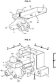
figure 7 est une vue schématique en coupe du dispositif d'amortissement suivant un second mode de réalisation de l'invention à l'état monté, - la
figure 8 est une vue schématique en perspective du dispositif d'amortissement suivant lafigure 7 à l'état monté, - la
figure 9 est une vue schématique en perspective du dispositif d'amortissement suivant lafigure 7 à l'état démonté.
- the
figure 1 is a schematic rear perspective view of the vibration damping device according to an embodiment of the invention in the mounted state, - the
figure 2 is a schematic sectional view of the vibration damping device according tofigure 1 in the assembled state, - the
figure 3 is a schematic front perspective view of the vibration damping device in the mounted state, - the
figure 4 is a schematic rear perspective view of the vibration damping device of thefigure 1 , - the
figure 5 is a schematic front perspective view of the vibration damping device of thefigure 3 , - the
figure 6 is a schematic exploded front perspective view of the vibration damping device of thefigure 1 , and - the
figure 7 is a schematic sectional view of the damping device according to a second embodiment of the invention in the mounted state, - the
figure 8 is a schematic perspective view of the damping device according tofigure 7 in the assembled state, - the
figure 9 is a schematic perspective view of the damping device according tofigure 7 in disassembled state.
Aux figures, l'invention est décrite en référence à trois directions orthonormales L, T et V de l'espace, à savoir une direction longitudinale horizontale L, une direction transversale horizontale T et une direction verticale V.In the figures, the invention is described with reference to three orthonormal directions L, T and V of space, namely a horizontal longitudinal direction L, a horizontal transverse direction T and a vertical direction V.
Aux figures, le corps 4 en élastomère est fixé à l'armature 3 dans une zone située à l'écart de l'ouverture 31 de passage du membre 2 dans l'armature 3 et à distance de la deuxième ouverture 32 servant au passage de la tête 22 du membre 2, ainsi que cela sera décrit ci-dessous. Le membre 2 est rigide et est par exemple métallique. L'armature 3 est rigide et par exemple métallique.In the figures, the
Le dispositif 1 d'amortissement de vibrations est destiné à être monté entre un premier élément E1 et un deuxième élément E2.The
Le dispositif 1 comporte le membre 2 destiné à être fixé au premier élément vibrant E1. Le membre 2 comporte un bras 21 s'étendant suivant la direction transversale T. Le bras 21 est destiné à être fixé au premier élément vibrant E1. Le membre 2 comporte également une tête 22, qui prolonge le bras 21 dans un premier sens t2 de la direction transversale T et qui est plus large que le bras 21 suivant la direction verticale V.The
En outre, le dispositif 1 comporte l'armature 3 destinée à être fixée au deuxième élément E2.In addition, the
Le premier élément vibrant E1 est un élément pouvant émettre des vibrations mécaniques, lorsqu'il est mis en fonctionnement et lorsque le dispositif 1 est à l'état monté. L'état monté du dispositif 1 s'entend lorsqu'à la fois le premier élément E1 est fixé au membre 2 et l'armature 3 est fixée au deuxième élément E2.The first vibrating element E1 is an element capable of emitting mechanical vibrations, when it is put into operation and when the
Le premier élément vibrant E1 peut être par exemple un moteur d'un véhicule automobile, tandis que le deuxième élément E2 peut être une caisse d'un véhicule automobile. A cet effet, le dispositif peut comporter des premiers moyens de fixation de l'armature 3 au deuxième élément E2.The first vibrating element E1 can be for example an engine of a motor vehicle, while the second element E2 can be a body of a motor vehicle. To this end, the device may include first means for fixing the
L'armature 3 a une forme générale ouverte, ayant deux ouvertures 31 et 32 assurant un passage suivant la direction transversale T. L'ouverture 32 étant ouverte dans sa partie supérieure. Ci-dessous, l'ouverture 32 est appelée première ouverture 32, l'ouverture 31 est appelée troisième ouverture 31 et l'ouverture 38 est appelée deuxième ouverture 38.The
L'armature 3 comporte une surface 37 délimitant l'ouverture 31. L'ouverture 31 s'étend autour de la direction transversale T. Cette ouverture 31 est plus large que le bras 21 et moins large que la tête 22. Ainsi, l'armature 3 entoure le bras 21 au niveau de cette première ouverture 31 et retient la tête 22.The
En outre, l'armature 3 comporte un contour 36 délimitant l'ouverture 32. L'ouverture 32 s'étend autour de la direction transversale T. Ainsi, la deuxième ouverture 32 permet le passage du membre 2 pour faire passer, lors du montage du dispositif 1 sur le véhicule automobile, le membre 2 de l'état démonté de la
Suivant un mode de réalisation, l'armature 3 comporte une surface 35 s'écartant de la première ouverture 31 en partant de la surface 37 délimitant l'ouverture 31. La surface 35 s'étend au moins dans le deuxième sens v1 (vertical descendant) de la direction verticale V. L'armature 3 comporte au moins une première patte 33 et au moins une deuxième patte 34, qui s'étendent dans le premier sens t2 en face de la deuxième ouverture 32 et qui sont positionnées en saillie en partant de la surface 35.According to one embodiment, the
Le corps 4 en élastomère comporte une partie supérieure 41 moulée autour de la tête 22. Le corps 4 en élastomère comporte également l'embase 42 ayant pour fonction la fixation du corps 4 en élastomère à l'armature 3. L'embase 42 prolonge la partie intermédiaire 41 dans le sens vertical v1 descendant. L'embase 42 comporte au moins un premier trou 421 et au moins un deuxième trou 422, qui s'étendent suivant la direction transversale T et par lesquels sont emmanchées en force respectivement la première patte 33 et la deuxième patte 34 pour la fixation du corps 4 en élastomère à l'armature 3. A cet effet, les premier et deuxième trous 421 et 422 peuvent avoir, à l'état démonté du membre 2, une première dimension inférieure à une deuxième dimension parallèle à la première dimension des première et deuxième pattes 33 et 34, ces dimensions étant prises dans un plan perpendiculaire à la direction transversale T. Ainsi, à l'état monté, lorsque les première et deuxième pattes 33 et 34 sont insérées dans respectivement les premier et deuxième trous 421 et 422, l'élastomère de l'embase 42 autour des premier et deuxième trous 421 et 422 est comprimé par les première et deuxième pattes 33 et 34, assurant une fixation de l'embase 42 aux première et deuxième pattes 33 et 34. Par exemple, les premier et deuxième trous 421 et 422 sont traversants. Toutefois, les premier et deuxième trous 421 et 422 pourraient être borgnes. Ainsi, à l'état monté, le corps 4 en élastomère est fixé autour des pattes 33 et 34 contre la troisième surface 35 qui, en étant à l'écart de la première ouverture 31, dispose de plus de place pour les pattes 33 et 34. Chaque patte 33, 34 peut être par exemple de forme arrondie, par exemple ovale ou circulaire, ou autre, autour de la direction longitudinale L, en pouvant être cylindrique autour de la direction transversale T.The
Suivant un mode de réalisation, l'embase 42 comporte deux jambes épaisses 425 et 426, situées dessous la tête 22 dans le premier sens vertical v1 et qui sert à la rigidification de l'embase 42 et du corps 4 en élastomère. La jambe 425 est celle entourant le trou 422 et la jambe 426 est celle entourant le trou 421.According to one embodiment, the
Suivant un mode de réalisation, l'armature 3 comporte une surface 331 située en face de la première patte 33 et une surface 341 située en face de la deuxième patte 34. Les surfaces 331 et 341 sont raccordées à la surface 363 et servent à appuyer respectivement contre les jambes 425 et 426. On renforce ainsi la fixation du corps 4 en élastomère à l'armature 3, ainsi que la rigidité du corps 4 en élastomère. A cet effet, les intervalles entre les première et deuxième pattes 33 et 34 et les surfaces 331 et 341 peuvent avoir, à l'état démonté du membre 2, une dimension inférieure à celle des parties élastomères des jambes 426 et 425 entourant les trous 421 et 422 destinées à y être insérées. Ainsi, à l'état monté, lorsque les première et deuxième pattes 33 et 34 sont insérées dans respectivement les premier et deuxième trous 421 et 422, l'élastomère de l'embase 44 situé entre les première et deuxième pattes 33 et 34 et les surfaces 331 et 341 est comprimé, assurant une meilleure fixation de l'embase 42 aux première et deuxième pattes 33 et 34.According to one embodiment, the
Ce mode d'assemblage permet d'avoir un maintien et un amortissement des vibrations tout en évitant de devoir adhériser le corps 4 en élastomère à une autre coupelle métallique distante du membre 2, ce qui simplifie la fabrication du dispositif 1 et diminue son coût.This method of assembly makes it possible to maintain and dampen vibrations while avoiding having to adhere the
Suivant un mode de réalisation, le corps 4 en élastomère comporte une protubérance 414 située en face et à distance d'une surface 351 de l'armature 3 dans un deuxième sens t1 de la direction transversale T, inverse du premier sens t2. Ainsi, cette protubérance 414 est apte à buter contre la surface 351 pour amortir les vibrations et limiter les déplacements du corps 4 en élastomère suivant le sens t1.According to one embodiment, the
Suivant un mode de réalisation, le corps 4 en élastomère comporte une protubérance 411 située en face et à distance d'une surface 361 de l'armature 3 dans un premier sens l1 de la direction longitudinale horizontale L. Ainsi, cette protubérance 411 est apte à buter contre la surface 361 pour amortir les vibrations et limiter les déplacements du corps 4 en élastomère suivant le sens l1.According to one embodiment, the
Suivant un mode de réalisation, le corps 4 en élastomère comporte une protubérance 412 située en face et à distance d'une surface 362 de l'armature 3 dans un deuxième sens l2 de la direction longitudinale horizontale L, inverse du premier sens l1. Ainsi, cette protubérance 412 est apte à buter contre la surface 362 pour amortir les vibrations et limiter les déplacements du corps 4 en élastomère suivant le sens l2.According to one embodiment, the
Suivant un mode de réalisation, le corps 4 en élastomère comporte une protubérance 413 située en face et à distance d'une surface 371 de l'armature 3 dans un sens vertical ascendant v2. Ainsi, cette protubérance 413 est apte à buter contre la surface 371 pour amortir les vibrations et limiter les déplacements du corps 4 en élastomère suivant le sens v2.According to one embodiment, the
Suivant un mode de réalisation, le corps 4 en élastomère comporte une protubérance 423 située en face et à distance d'une surface 363 de l'armature 3 dans un sens vertical descendant v1. Ainsi, cette protubérance 423 est apte à buter contre la surface 363 pour amortir les vibrations et limiter les déplacements du corps 4 en élastomère suivant le sens v1.According to one embodiment, the
Suivant un mode de réalisation, le corps 4 en élastomère comporte une protubérance 415 située en face et à distance d'une surface préalablement aménagée sur l'élément E2 en face de la partie supérieure de la seconde ouverture 32 dans le sens t2. Ainsi, cette protubérance 415 est apte à buter contre la surface de l'élément E2 pour amortir les vibrations et limiter les déplacements du corps 4 en élastomère suivant le sens t2.According to one embodiment, the
Suivant un mode de réalisation, représenté sur les
Ainsi, le corps 4 en élastomère est positionné pour buter, dans les deux sens des trois directions orthonormales L, T et V de l'espace, contre des surfaces correspondantes 361, 362, 363, 371, 351 de l'armature 3 et une surface préalablement aménagée sur l'élément E2 ou sur la caisse du véhicule automobile en face de la partie supérieure de l'ouverture 32 de l'armature 3.Thus, the
Ainsi, l'élément 1 assure la filtration, l'amortissement des vibrations et la limitation des débattements suivant les 2 sens des 3 directions L, T et V entre l'élément E1 et l'élément E2.Thus,
Suivant un second mode de réalisation, représenté aux
Ainsi, le déplacement du corps 4 en élastomère dans le premier sens longitudinal t2 est limité par la surface 381 faisant partie de l'armature 3. Ainsi, la deuxième ouverture 32, peut rester béante sans devoir être fermée par une paroi de l'élément E2, du fait que le corps 4 en élastomère est apte à buter par son prolongement transversal 43 contre la surface 381 dans le sens t1. Le prolongement 43 peut être situé sensiblement contre la surface 381 à l'état monté, avec donc une distance sensiblement nulle ou très petite entre la surface 381 et le prolongement 43.Thus, the movement of the
Suivant ce second mode de réalisation, le dispositif comporte une goupille 5, qui, à l'état monté, est fixée à la tête 22 et qui s'étend dans la troisième ouverture 38 suivant le sens v1. A l'état monté, la goupille 5 est située au centre du prolongement vertical 43. Cette goupille 5 permet de renforcer la tenue du prolongement 43 contre la surface 381.According to this second embodiment, the device comprises a
Suivant ce second mode de de réalisation, le prolongement 43 est situé entre la première jambe 425 et la deuxième jambe 426. L'embase 42 offre ainsi, par les jambes 425 et 426, une assise stable et rigidifiée au prolongement transversal 43.According to this second embodiment, the
Suivant ce second mode de réalisation, la goupille 5 est une pièce amovible, rapportée sur la tête 22 lorsque le prolongement transversal 43 est inséré dans l'ouverture 38. Ainsi, pour monter le dispositif 1, on insère d'abord le bras 21 dans l'ouverture 31 en insérant la tête 22 au travers de l'ouverture 32 et on enfile l'embase 42 autour des pattes 33 et 34 de manière à faire passer le prolongement43 dans l'ouverture 38, par déformation de ce prolongement vertical 43. Puis, on insère la goupille 5 dans la tête 22 en traversant l'ouverture 38 et le corps 4 en élastomère.According to this second embodiment, the
A cet effet, suivant ce second mode de réalisation, le prolongement vertical 43 comporte un trou 431 de passage de la goupille 5.To this end, according to this second embodiment, the
Suivant ce second mode de réalisation, la tête 22 comporte un trou 221 d'insertion de la goupille 5 dans la tête 22.According to this second embodiment, the
Suivant ce second mode de réalisation, représenté sur la
Suivant ce mode de réalisation, l'embase 42 du corps élastomère 4 étant maintenue par les pattes 33 et 34 et les surfaces 331 et 341, cette embase 42 ne nécessite donc pas d'ajout d'une quelconque armature métallique complémentaire pour assurer son maintien au sein de l'élément 3.According to this embodiment, the
Ainsi, suivant ce second mode de réalisation, le corps 4 en élastomère est positionné pour buter, dans les deux sens des trois directions orthonormales L, T et V de l'espace, contre des surfaces correspondantes 361, 362, 363, 351, 371 et 381 de l'armature 3, se dispensant ainsi de buter contre le deuxième élément E2 ou contre la caisse du véhicule automobile.Thus, according to this second embodiment, the
Bien entendu, il pourrait être prévu une seule patte et une embase 42 ayant un seul trou dans lequel est emmanché en force la patte ou une seule jambe ayant un seul trou dans lequel est emmanché en force la patte, le terme deux pouvant être remplacé par au moins un dans ce qui précède.Of course, there could be a single leg and a base 42 having a single hole in which the leg is force-fitted or a single leg having a single hole in which the leg is force-fitted, the term two being able to be replaced by at least one in the above.
Bien entendu, chaque caractéristique indiquée ci-dessus peut être sélectionnée indépendamment des autres caractéristiques ou être combinée à une ou plusieurs autres caractéristiques dans le dispositif.Of course, each characteristic indicated above can be selected independently of the other characteristics or be combined with one or more other characteristics in the device.
Claims (5)
- A device (1) for damping vibrations between a first vibrating element (E1) and a second element (E2),
the device including:a member (2) designed to be attached to the first vibrating element (E1), the member (2) including an arm (21) extending along a transverse horizontal direction (T) and a head (22), which prolongs the arm (21) in a first orientation (t2) of the transverse direction (T),a framework (3) designed to be attached to the second element (E2),a body (4) made of elastomer attached to the member (2) and turned toward the framework (3),wherein the framework (3) comprises at least one first tab (33), at least one second tab (34), at least one first surface (331) and at least one second surface (332), which extend in the first orientation (t2) in front of a first opening (32) of the framework (3),the body (4) made of elastomer comprising an upper portion (41) molded around the head (22) and a base (42) comprising at least two elastomer legs (425, 426), characterized in that these legs have at least two holes (421,422),the retention of the base (42) of the body (4) in the framework (3) being ensured by fitting of the legs (425,426) over the tabs (33,34) respectively through the holes (421,422) and by compressing of the elastomer of the legs (425, 426) between respectively the first and second surfaces (331, 332) and the first and second tabs (33,34), wherein the head is wider than the arm (21) in a vertical direction (V). - The device according to claim 1, characterized in that
the upper portion (41) comprises protuberances (411, 412, 413, 414, 423), these protuberances coming into abutment respectively on other surfaces (361, 362, 371, 351, 363) of the framework (3), these protuberances damping and limiting the displacements between the first element (E1) and the second element (E2) in respectively:- both orientations (11, 12) of a horizontal longitudinal direction,- an ascending vertical orientation (v2),- a second orientation (t1) of the transverse direction (T), the reverse of the first orientation (t2),- a vertical descending orientation (v1). - The device according to one of claims 1 and 2, characterized in that
the upper portion (41) includes a protuberance (415) coming into abutment in the upper portion of the first opening (32) on a surface provided on the second element (E2), this protuberance damping and limiting the displacement along the first orientation (t2). - The device according to one of claims 1 and 2, characterized in that
the base (42) of the elastomer body (4) is connected in a vertical orientation (v1) to a vertical prolongation (43),
the framework (3) including a third surface (39) in which is provided a second opening (38) extending around the vertical direction (V) and being, along the transverse direction (T) and a horizontal longitudinal direction (L), wider than the prolongation (43), the prolongation (43) passing through the second opening (36),
the framework (3) having at least one fourth surface (381) which is situated facing the vertical prolongation (43) in the first orientation (t2). - The device according to claim 4, characterized in that
a removable pin (5) is inserted in the direction (V) in a hole (431) in the prolongation (43) and is fitted into a hole (221) in the head (22) to become integral with the head (22), this pin (5) extending into the third opening (38) of the framework (3),
the prolongation (43) damps and limits the displacement of the element (2) in the first orientation (t2) by coming into contact with the fourth surface (381) of the framework (3).
Applications Claiming Priority (2)
| Application Number | Priority Date | Filing Date | Title |
|---|---|---|---|
| FR1651856A FR3048474B1 (en) | 2016-03-04 | 2016-03-04 | DEVICE FOR DAMPING VIBRATIONS BETWEEN A FIRST VIBRATING ELEMENT AND A SECOND ELEMENT |
| PCT/EP2017/053458 WO2017148707A1 (en) | 2016-03-04 | 2017-02-16 | Device for damping vibrations between a first vibrating element and a second element |
Publications (2)
| Publication Number | Publication Date |
|---|---|
| EP3423733A1 EP3423733A1 (en) | 2019-01-09 |
| EP3423733B1 true EP3423733B1 (en) | 2021-01-13 |
Family
ID=55808708
Family Applications (1)
| Application Number | Title | Priority Date | Filing Date |
|---|---|---|---|
| EP17704500.2A Active EP3423733B1 (en) | 2016-03-04 | 2017-02-16 | Vibration damping device between a first vibrating element and a second element |
Country Status (5)
| Country | Link |
|---|---|
| EP (1) | EP3423733B1 (en) |
| CN (1) | CN109073021B (en) |
| BR (1) | BR112018067686A2 (en) |
| FR (1) | FR3048474B1 (en) |
| WO (1) | WO2017148707A1 (en) |
Families Citing this family (2)
| Publication number | Priority date | Publication date | Assignee | Title |
|---|---|---|---|---|
| US10738853B2 (en) | 2017-08-09 | 2020-08-11 | Vibracoustic Usa, Inc. | Damper and assembly |
| FR3132341A1 (en) * | 2022-01-31 | 2023-08-04 | Psa Automobiles Sa | MOTOR VEHICLE POWERTRAIN ELASTIC MOUNT |
Family Cites Families (9)
| Publication number | Priority date | Publication date | Assignee | Title |
|---|---|---|---|---|
| FR2829208B1 (en) | 2001-09-05 | 2003-12-05 | Hutchinson | ANTI-VIBRATORY ASSEMBLY AND ANTI-VIBRATORY SUPPORT BEING PART OF THIS ASSEMBLY |
| DE10249387C5 (en) * | 2002-10-23 | 2008-07-03 | Telleborg Automotive Technical Centre Gmbh | Elastic bearing, in particular for supporting a transmission or the engine of a motor vehicle |
| US7644911B2 (en) * | 2005-09-22 | 2010-01-12 | The Pullman Company | Isolator |
| JP5297275B2 (en) * | 2009-06-18 | 2013-09-25 | 東洋ゴム工業株式会社 | Vibration isolator |
| DE102010024903A1 (en) * | 2010-06-24 | 2011-12-29 | Anvis Deutschland Gmbh | Apparatus for resiliently supporting an engine and method of making the same |
| US8403097B2 (en) * | 2011-04-19 | 2013-03-26 | Paulstra Crc | Movement limiting anti-vibration assembly |
| JP2013117259A (en) * | 2011-12-02 | 2013-06-13 | Bridgestone Corp | Vibration damping device |
| JP6190651B2 (en) * | 2013-07-23 | 2017-08-30 | 住友理工株式会社 | Vibration isolator |
| WO2015145672A1 (en) * | 2014-03-27 | 2015-10-01 | 住友理工株式会社 | Anti-vibration device |
-
2016
- 2016-03-04 FR FR1651856A patent/FR3048474B1/en active Active
-
2017
- 2017-02-16 CN CN201780015166.2A patent/CN109073021B/en active Active
- 2017-02-16 WO PCT/EP2017/053458 patent/WO2017148707A1/en active Application Filing
- 2017-02-16 BR BR112018067686A patent/BR112018067686A2/en not_active Application Discontinuation
- 2017-02-16 EP EP17704500.2A patent/EP3423733B1/en active Active
Non-Patent Citations (1)
| Title |
|---|
| None * |
Also Published As
| Publication number | Publication date |
|---|---|
| WO2017148707A1 (en) | 2017-09-08 |
| FR3048474A1 (en) | 2017-09-08 |
| CN109073021B (en) | 2020-10-23 |
| EP3423733A1 (en) | 2019-01-09 |
| FR3048474B1 (en) | 2018-04-20 |
| CN109073021A (en) | 2018-12-21 |
| BR112018067686A2 (en) | 2019-01-08 |
Similar Documents
| Publication | Publication Date | Title |
|---|---|---|
| EP1217249B1 (en) | Anti-vibration bush and motor vehicle comprising said bush | |
| EP1306576A1 (en) | Hydraulic antivibration support with a snap-fitted decoupling valve | |
| EP1390639B1 (en) | Anti-vibration mount and production method for same | |
| EP2266829B1 (en) | Vibration isolator with limited movement | |
| EP1176336A1 (en) | Hydraulic antivibration support and motor vehicle comprising said support | |
| EP1283377B1 (en) | Hydraulic damping support | |
| EP3423733B1 (en) | Vibration damping device between a first vibrating element and a second element | |
| EP2282076B1 (en) | Anti-vibration device for a vehicle and vehicle including such a device | |
| EP0894995B1 (en) | Hydraulic damping support | |
| EP3126209B1 (en) | Reinforced vehicle structure | |
| EP3029351A1 (en) | Controllable hydraulic anti-vibration mounting | |
| EP0800017B1 (en) | Hydraulic antivibration support and motor vehicle subassembly with said support | |
| EP3523552B1 (en) | Anti-vibratory support for a motor vehicle and motor vehicle equipped with same | |
| EP1155894B1 (en) | Damping support, and vehicle comprising such a support | |
| EP1291543B1 (en) | Anti-vibration assembly and component damping mount | |
| EP3196103B1 (en) | Device for attaching a shock-absorber rod to a motor vehicle body | |
| EP1348876A1 (en) | Fixing and vibration isolating device made of two materials | |
| EP1293701B1 (en) | Antivibration support and antivibration device comprising the same | |
| EP0894996B1 (en) | Hydraulic damping support | |
| EP0845617B1 (en) | Anti-vibration support, and vehicle with such a support | |
| EP0961048B1 (en) | Hydraulic damping support | |
| EP1291544B1 (en) | Anti-vibration support and vehicle with such a support | |
| FR2808854A1 (en) | Anti-vibration mounting for vehicle engine comprises rigid, T-shaped armature attached to engine and metal or plastic tubes attached to chassis by bolts, sloping elastomeric arms being positioned between tubes and armature |
Legal Events
| Date | Code | Title | Description |
|---|---|---|---|
| STAA | Information on the status of an ep patent application or granted ep patent |
Free format text: STATUS: UNKNOWN |
|
| STAA | Information on the status of an ep patent application or granted ep patent |
Free format text: STATUS: THE INTERNATIONAL PUBLICATION HAS BEEN MADE |
|
| PUAI | Public reference made under article 153(3) epc to a published international application that has entered the european phase |
Free format text: ORIGINAL CODE: 0009012 |
|
| STAA | Information on the status of an ep patent application or granted ep patent |
Free format text: STATUS: REQUEST FOR EXAMINATION WAS MADE |
|
| 17P | Request for examination filed |
Effective date: 20180904 |
|
| AK | Designated contracting states |
Kind code of ref document: A1 Designated state(s): AL AT BE BG CH CY CZ DE DK EE ES FI FR GB GR HR HU IE IS IT LI LT LU LV MC MK MT NL NO PL PT RO RS SE SI SK SM TR |
|
| AX | Request for extension of the european patent |
Extension state: BA ME |
|
| DAX | Request for extension of the european patent (deleted) | ||
| RAV | Requested validation state of the european patent: fee paid |
Extension state: MA Effective date: 20180904 |
|
| GRAP | Despatch of communication of intention to grant a patent |
Free format text: ORIGINAL CODE: EPIDOSNIGR1 |
|
| STAA | Information on the status of an ep patent application or granted ep patent |
Free format text: STATUS: GRANT OF PATENT IS INTENDED |
|
| INTG | Intention to grant announced |
Effective date: 20191114 |
|
| GRAS | Grant fee paid |
Free format text: ORIGINAL CODE: EPIDOSNIGR3 |
|
| GRAA | (expected) grant |
Free format text: ORIGINAL CODE: 0009210 |
|
| STAA | Information on the status of an ep patent application or granted ep patent |
Free format text: STATUS: THE PATENT HAS BEEN GRANTED |
|
| AK | Designated contracting states |
Kind code of ref document: B1 Designated state(s): AL AT BE BG CH CY CZ DE DK EE ES FI FR GB GR HR HU IE IS IT LI LT LU LV MC MK MT NL NO PL PT RO RS SE SI SK SM TR |
|
| REG | Reference to a national code |
Ref country code: GB Ref legal event code: FG4D Free format text: NOT ENGLISH |
|
| REG | Reference to a national code |
Ref country code: CH Ref legal event code: EP |
|
| REG | Reference to a national code |
Ref country code: DE Ref legal event code: R096 Ref document number: 602017031325 Country of ref document: DE |
|
| REG | Reference to a national code |
Ref country code: IE Ref legal event code: FG4D Free format text: LANGUAGE OF EP DOCUMENT: FRENCH |
|
| REG | Reference to a national code |
Ref country code: AT Ref legal event code: REF Ref document number: 1354807 Country of ref document: AT Kind code of ref document: T Effective date: 20210215 |
|
| PGFP | Annual fee paid to national office [announced via postgrant information from national office to epo] |
Ref country code: FR Payment date: 20210226 Year of fee payment: 5 |
|
| REG | Reference to a national code |
Ref country code: AT Ref legal event code: MK05 Ref document number: 1354807 Country of ref document: AT Kind code of ref document: T Effective date: 20210113 |
|
| REG | Reference to a national code |
Ref country code: NL Ref legal event code: MP Effective date: 20210113 |
|
| REG | Reference to a national code |
Ref country code: LT Ref legal event code: MG9D |
|
| RAP2 | Party data changed (patent owner data changed or rights of a patent transferred) |
Owner name: CONTITECH VIBRATION CONTROL GMBH |
|
| PG25 | Lapsed in a contracting state [announced via postgrant information from national office to epo] |
Ref country code: BG Free format text: LAPSE BECAUSE OF FAILURE TO SUBMIT A TRANSLATION OF THE DESCRIPTION OR TO PAY THE FEE WITHIN THE PRESCRIBED TIME-LIMIT Effective date: 20210413 Ref country code: LT Free format text: LAPSE BECAUSE OF FAILURE TO SUBMIT A TRANSLATION OF THE DESCRIPTION OR TO PAY THE FEE WITHIN THE PRESCRIBED TIME-LIMIT Effective date: 20210113 Ref country code: GR Free format text: LAPSE BECAUSE OF FAILURE TO SUBMIT A TRANSLATION OF THE DESCRIPTION OR TO PAY THE FEE WITHIN THE PRESCRIBED TIME-LIMIT Effective date: 20210414 Ref country code: HR Free format text: LAPSE BECAUSE OF FAILURE TO SUBMIT A TRANSLATION OF THE DESCRIPTION OR TO PAY THE FEE WITHIN THE PRESCRIBED TIME-LIMIT Effective date: 20210113 Ref country code: FI Free format text: LAPSE BECAUSE OF FAILURE TO SUBMIT A TRANSLATION OF THE DESCRIPTION OR TO PAY THE FEE WITHIN THE PRESCRIBED TIME-LIMIT Effective date: 20210113 Ref country code: PT Free format text: LAPSE BECAUSE OF FAILURE TO SUBMIT A TRANSLATION OF THE DESCRIPTION OR TO PAY THE FEE WITHIN THE PRESCRIBED TIME-LIMIT Effective date: 20210513 Ref country code: NO Free format text: LAPSE BECAUSE OF FAILURE TO SUBMIT A TRANSLATION OF THE DESCRIPTION OR TO PAY THE FEE WITHIN THE PRESCRIBED TIME-LIMIT Effective date: 20210413 |
|
| PG25 | Lapsed in a contracting state [announced via postgrant information from national office to epo] |
Ref country code: AT Free format text: LAPSE BECAUSE OF FAILURE TO SUBMIT A TRANSLATION OF THE DESCRIPTION OR TO PAY THE FEE WITHIN THE PRESCRIBED TIME-LIMIT Effective date: 20210113 Ref country code: LV Free format text: LAPSE BECAUSE OF FAILURE TO SUBMIT A TRANSLATION OF THE DESCRIPTION OR TO PAY THE FEE WITHIN THE PRESCRIBED TIME-LIMIT Effective date: 20210113 Ref country code: PL Free format text: LAPSE BECAUSE OF FAILURE TO SUBMIT A TRANSLATION OF THE DESCRIPTION OR TO PAY THE FEE WITHIN THE PRESCRIBED TIME-LIMIT Effective date: 20210113 Ref country code: RS Free format text: LAPSE BECAUSE OF FAILURE TO SUBMIT A TRANSLATION OF THE DESCRIPTION OR TO PAY THE FEE WITHIN THE PRESCRIBED TIME-LIMIT Effective date: 20210113 Ref country code: SE Free format text: LAPSE BECAUSE OF FAILURE TO SUBMIT A TRANSLATION OF THE DESCRIPTION OR TO PAY THE FEE WITHIN THE PRESCRIBED TIME-LIMIT Effective date: 20210113 |
|
| PG25 | Lapsed in a contracting state [announced via postgrant information from national office to epo] |
Ref country code: IS Free format text: LAPSE BECAUSE OF FAILURE TO SUBMIT A TRANSLATION OF THE DESCRIPTION OR TO PAY THE FEE WITHIN THE PRESCRIBED TIME-LIMIT Effective date: 20210513 |
|
| REG | Reference to a national code |
Ref country code: DE Ref legal event code: R097 Ref document number: 602017031325 Country of ref document: DE |
|
| REG | Reference to a national code |
Ref country code: BE Ref legal event code: MM Effective date: 20210228 |
|
| PG25 | Lapsed in a contracting state [announced via postgrant information from national office to epo] |
Ref country code: CH Free format text: LAPSE BECAUSE OF NON-PAYMENT OF DUE FEES Effective date: 20210228 Ref country code: SM Free format text: LAPSE BECAUSE OF FAILURE TO SUBMIT A TRANSLATION OF THE DESCRIPTION OR TO PAY THE FEE WITHIN THE PRESCRIBED TIME-LIMIT Effective date: 20210113 Ref country code: CZ Free format text: LAPSE BECAUSE OF FAILURE TO SUBMIT A TRANSLATION OF THE DESCRIPTION OR TO PAY THE FEE WITHIN THE PRESCRIBED TIME-LIMIT Effective date: 20210113 Ref country code: EE Free format text: LAPSE BECAUSE OF FAILURE TO SUBMIT A TRANSLATION OF THE DESCRIPTION OR TO PAY THE FEE WITHIN THE PRESCRIBED TIME-LIMIT Effective date: 20210113 Ref country code: LI Free format text: LAPSE BECAUSE OF NON-PAYMENT OF DUE FEES Effective date: 20210228 Ref country code: LU Free format text: LAPSE BECAUSE OF NON-PAYMENT OF DUE FEES Effective date: 20210216 Ref country code: MC Free format text: LAPSE BECAUSE OF FAILURE TO SUBMIT A TRANSLATION OF THE DESCRIPTION OR TO PAY THE FEE WITHIN THE PRESCRIBED TIME-LIMIT Effective date: 20210113 |
|
| PLBE | No opposition filed within time limit |
Free format text: ORIGINAL CODE: 0009261 |
|
| STAA | Information on the status of an ep patent application or granted ep patent |
Free format text: STATUS: NO OPPOSITION FILED WITHIN TIME LIMIT |
|
| PG25 | Lapsed in a contracting state [announced via postgrant information from national office to epo] |
Ref country code: DK Free format text: LAPSE BECAUSE OF FAILURE TO SUBMIT A TRANSLATION OF THE DESCRIPTION OR TO PAY THE FEE WITHIN THE PRESCRIBED TIME-LIMIT Effective date: 20210113 Ref country code: SK Free format text: LAPSE BECAUSE OF FAILURE TO SUBMIT A TRANSLATION OF THE DESCRIPTION OR TO PAY THE FEE WITHIN THE PRESCRIBED TIME-LIMIT Effective date: 20210113 Ref country code: RO Free format text: LAPSE BECAUSE OF FAILURE TO SUBMIT A TRANSLATION OF THE DESCRIPTION OR TO PAY THE FEE WITHIN THE PRESCRIBED TIME-LIMIT Effective date: 20210113 |
|
| 26N | No opposition filed |
Effective date: 20211014 |
|
| PG25 | Lapsed in a contracting state [announced via postgrant information from national office to epo] |
Ref country code: IE Free format text: LAPSE BECAUSE OF NON-PAYMENT OF DUE FEES Effective date: 20210216 Ref country code: ES Free format text: LAPSE BECAUSE OF FAILURE TO SUBMIT A TRANSLATION OF THE DESCRIPTION OR TO PAY THE FEE WITHIN THE PRESCRIBED TIME-LIMIT Effective date: 20210113 Ref country code: AL Free format text: LAPSE BECAUSE OF FAILURE TO SUBMIT A TRANSLATION OF THE DESCRIPTION OR TO PAY THE FEE WITHIN THE PRESCRIBED TIME-LIMIT Effective date: 20210113 |
|
| PG25 | Lapsed in a contracting state [announced via postgrant information from national office to epo] |
Ref country code: SI Free format text: LAPSE BECAUSE OF FAILURE TO SUBMIT A TRANSLATION OF THE DESCRIPTION OR TO PAY THE FEE WITHIN THE PRESCRIBED TIME-LIMIT Effective date: 20210113 |
|
| PG25 | Lapsed in a contracting state [announced via postgrant information from national office to epo] |
Ref country code: IT Free format text: LAPSE BECAUSE OF FAILURE TO SUBMIT A TRANSLATION OF THE DESCRIPTION OR TO PAY THE FEE WITHIN THE PRESCRIBED TIME-LIMIT Effective date: 20210113 |
|
| PG25 | Lapsed in a contracting state [announced via postgrant information from national office to epo] |
Ref country code: IS Free format text: LAPSE BECAUSE OF FAILURE TO SUBMIT A TRANSLATION OF THE DESCRIPTION OR TO PAY THE FEE WITHIN THE PRESCRIBED TIME-LIMIT Effective date: 20210513 |
|
| PG25 | Lapsed in a contracting state [announced via postgrant information from national office to epo] |
Ref country code: BE Free format text: LAPSE BECAUSE OF NON-PAYMENT OF DUE FEES Effective date: 20210228 |
|
| PG25 | Lapsed in a contracting state [announced via postgrant information from national office to epo] |
Ref country code: FR Free format text: LAPSE BECAUSE OF NON-PAYMENT OF DUE FEES Effective date: 20220228 |
|
| PGFP | Annual fee paid to national office [announced via postgrant information from national office to epo] |
Ref country code: GB Payment date: 20230221 Year of fee payment: 7 Ref country code: DE Payment date: 20230228 Year of fee payment: 7 |
|
| PG25 | Lapsed in a contracting state [announced via postgrant information from national office to epo] |
Ref country code: NL Free format text: LAPSE BECAUSE OF NON-PAYMENT OF DUE FEES Effective date: 20210113 Ref country code: CY Free format text: LAPSE BECAUSE OF FAILURE TO SUBMIT A TRANSLATION OF THE DESCRIPTION OR TO PAY THE FEE WITHIN THE PRESCRIBED TIME-LIMIT Effective date: 20210113 |
|
| PG25 | Lapsed in a contracting state [announced via postgrant information from national office to epo] |
Ref country code: HU Free format text: LAPSE BECAUSE OF FAILURE TO SUBMIT A TRANSLATION OF THE DESCRIPTION OR TO PAY THE FEE WITHIN THE PRESCRIBED TIME-LIMIT; INVALID AB INITIO Effective date: 20170216 |