EP3523552B1 - Anti-vibratory support for a motor vehicle and motor vehicle equipped with same - Google Patents
Anti-vibratory support for a motor vehicle and motor vehicle equipped with same Download PDFInfo
- Publication number
- EP3523552B1 EP3523552B1 EP16788736.3A EP16788736A EP3523552B1 EP 3523552 B1 EP3523552 B1 EP 3523552B1 EP 16788736 A EP16788736 A EP 16788736A EP 3523552 B1 EP3523552 B1 EP 3523552B1
- Authority
- EP
- European Patent Office
- Prior art keywords
- vibration support
- reinforcement
- opening
- support according
- thermoplastic material
- Prior art date
- Legal status (The legal status is an assumption and is not a legal conclusion. Google has not performed a legal analysis and makes no representation as to the accuracy of the status listed.)
- Active
Links
Images


Classifications
-
- F—MECHANICAL ENGINEERING; LIGHTING; HEATING; WEAPONS; BLASTING
- F16—ENGINEERING ELEMENTS AND UNITS; GENERAL MEASURES FOR PRODUCING AND MAINTAINING EFFECTIVE FUNCTIONING OF MACHINES OR INSTALLATIONS; THERMAL INSULATION IN GENERAL
- F16F—SPRINGS; SHOCK-ABSORBERS; MEANS FOR DAMPING VIBRATION
- F16F15/00—Suppression of vibrations in systems; Means or arrangements for avoiding or reducing out-of-balance forces, e.g. due to motion
- F16F15/02—Suppression of vibrations of non-rotating, e.g. reciprocating systems; Suppression of vibrations of rotating systems by use of members not moving with the rotating systems
- F16F15/04—Suppression of vibrations of non-rotating, e.g. reciprocating systems; Suppression of vibrations of rotating systems by use of members not moving with the rotating systems using elastic means
- F16F15/08—Suppression of vibrations of non-rotating, e.g. reciprocating systems; Suppression of vibrations of rotating systems by use of members not moving with the rotating systems using elastic means with rubber springs ; with springs made of rubber and metal
-
- F—MECHANICAL ENGINEERING; LIGHTING; HEATING; WEAPONS; BLASTING
- F16—ENGINEERING ELEMENTS AND UNITS; GENERAL MEASURES FOR PRODUCING AND MAINTAINING EFFECTIVE FUNCTIONING OF MACHINES OR INSTALLATIONS; THERMAL INSULATION IN GENERAL
- F16F—SPRINGS; SHOCK-ABSORBERS; MEANS FOR DAMPING VIBRATION
- F16F1/00—Springs
- F16F1/36—Springs made of rubber or other material having high internal friction, e.g. thermoplastic elastomers
- F16F1/373—Springs made of rubber or other material having high internal friction, e.g. thermoplastic elastomers characterised by having a particular shape
- F16F1/3732—Springs made of rubber or other material having high internal friction, e.g. thermoplastic elastomers characterised by having a particular shape having an annular or the like shape, e.g. grommet-type resilient mountings
-
- F—MECHANICAL ENGINEERING; LIGHTING; HEATING; WEAPONS; BLASTING
- F16—ENGINEERING ELEMENTS AND UNITS; GENERAL MEASURES FOR PRODUCING AND MAINTAINING EFFECTIVE FUNCTIONING OF MACHINES OR INSTALLATIONS; THERMAL INSULATION IN GENERAL
- F16F—SPRINGS; SHOCK-ABSORBERS; MEANS FOR DAMPING VIBRATION
- F16F1/00—Springs
- F16F1/36—Springs made of rubber or other material having high internal friction, e.g. thermoplastic elastomers
- F16F1/3605—Springs made of rubber or other material having high internal friction, e.g. thermoplastic elastomers characterised by their material
-
- B—PERFORMING OPERATIONS; TRANSPORTING
- B60—VEHICLES IN GENERAL
- B60K—ARRANGEMENT OR MOUNTING OF PROPULSION UNITS OR OF TRANSMISSIONS IN VEHICLES; ARRANGEMENT OR MOUNTING OF PLURAL DIVERSE PRIME-MOVERS IN VEHICLES; AUXILIARY DRIVES FOR VEHICLES; INSTRUMENTATION OR DASHBOARDS FOR VEHICLES; ARRANGEMENTS IN CONNECTION WITH COOLING, AIR INTAKE, GAS EXHAUST OR FUEL SUPPLY OF PROPULSION UNITS IN VEHICLES
- B60K5/00—Arrangement or mounting of internal-combustion or jet-propulsion units
- B60K5/12—Arrangement of engine supports
- B60K5/1266—Supports comprising friction damping devices
-
- F—MECHANICAL ENGINEERING; LIGHTING; HEATING; WEAPONS; BLASTING
- F16—ENGINEERING ELEMENTS AND UNITS; GENERAL MEASURES FOR PRODUCING AND MAINTAINING EFFECTIVE FUNCTIONING OF MACHINES OR INSTALLATIONS; THERMAL INSULATION IN GENERAL
- F16F—SPRINGS; SHOCK-ABSORBERS; MEANS FOR DAMPING VIBRATION
- F16F2224/00—Materials; Material properties
- F16F2224/02—Materials; Material properties solids
- F16F2224/0241—Fibre-reinforced plastics [FRP]
-
- F—MECHANICAL ENGINEERING; LIGHTING; HEATING; WEAPONS; BLASTING
- F16—ENGINEERING ELEMENTS AND UNITS; GENERAL MEASURES FOR PRODUCING AND MAINTAINING EFFECTIVE FUNCTIONING OF MACHINES OR INSTALLATIONS; THERMAL INSULATION IN GENERAL
- F16F—SPRINGS; SHOCK-ABSORBERS; MEANS FOR DAMPING VIBRATION
- F16F2224/00—Materials; Material properties
- F16F2224/02—Materials; Material properties solids
- F16F2224/025—Elastomers
-
- F—MECHANICAL ENGINEERING; LIGHTING; HEATING; WEAPONS; BLASTING
- F16—ENGINEERING ELEMENTS AND UNITS; GENERAL MEASURES FOR PRODUCING AND MAINTAINING EFFECTIVE FUNCTIONING OF MACHINES OR INSTALLATIONS; THERMAL INSULATION IN GENERAL
- F16F—SPRINGS; SHOCK-ABSORBERS; MEANS FOR DAMPING VIBRATION
- F16F2230/00—Purpose; Design features
- F16F2230/0005—Attachment, e.g. to facilitate mounting onto confer adjustability
Definitions
- the invention relates to an anti-vibration support.
- a field of application of the invention relates to motor vehicles in which a vibrating part, such as for example an engine, is mounted on the body by means of one or more anti-vibration mounts.
- the vibrating part tends to transmit vibrations to the body via the support.
- the anti-vibration support must enable the motor vehicle to successfully pass the mechanical strength tests, in particular the crash tests.
- the aim of the invention is to obtain an anti-vibration support, which is light in weight and does not penalize either the mechanical strength, or the damping of vibrations, or the filtering of vibrations, which must be provided by the anti-vibration support.
- the subject of the invention is an anti-vibration support according to claim 1.
- the anti-vibration support provides good mechanical resistance to the forces exerted between the first metal reinforcement and the second metal reinforcement, which makes it possible to successfully pass the collision tests, requiring that this mechanical resistance be greater than a prescribed value.
- the reinforcement can be of various shapes.
- the first metal reinforcement is connected to the second metal reinforcement by an assembly of generally annular shape (body made of thermoplastic material, reinforcement, part made of elastomer) which is both lighter in weight compared to metal and by making the link with the third metal armature to be fixed to the vibrating part and which makes it possible to dampen the vibrations originating from the latter and sent to this third armature metallic.
- body made of thermoplastic material, reinforcement, part made of elastomer
- the third metal reinforcement (5) comprises at least one third opening (53) for crossing in the second direction (D2), located above the second opening (23) in the second steering (D2).
- the reinforcement (3) extends in a direction (SE) of substantially horizontal winding around the second direction (D2), and is made of unidirectional continuous fibers extending in the direction (SE) winding and embedded in a polymer to form the prefabricated part having the shape of a loop (30).
- the second opening (23) of the part (2) made of elastomer passes through the first opening (43) of the body (4) made of thermoplastic material in the second direction (D2).
- the reinforcement (3) extends around the second direction (D2) and surrounds the first opening (43) and the second opening (23).
- the elastomer part (2) comprises an upper portion (22) covering a part (410) of the surface upper (41) of the body (4) of thermoplastic material and supporting the third armature (5).
- the first and second surfaces (112, 122) are vertical.
- the elastomer part (2) comprises a first abutment protrusion (24a) and a second abutment protrusion (24b), which are intended to abut downwards against other corresponding parts of the anti-vibration support and which are separated from each other transversely to a second substantially vertical direction (D2).
- the first and second armatures (11, 12) respectively comprise first and second holes (113, 123), which are used for crossing in a second substantially vertical direction (D2) for fixing to the motor vehicle body and which are respectively delimited by third and fourth free surfaces (114, 124), accessible from the outside and connected to the first and second surfaces (112, 122).
- the first and second armatures (11, 12) are formed by respectively first and second rings (11, 12) delimiting the first and second holes (113, 123), the third and fourth free surfaces (114, 124) being located on the inside of the first and second rings (11, 12), the first and second surfaces (112, 122) being located on the outside of the first and second rings (11, 12).
- the third and fourth surfaces (114, 124) and the first and second holes (1113, 1213) are located on respectively first and second external fixing lugs (115, 125) projecting towards the outside of the body (4) in the first substantially horizontal direction (D1).
- the first and second legs (115, 125) are horizontal and angled with respect to the first and second vertical surfaces (112, 122).
- a second object of the invention is a motor vehicle, comprising a body, an engine mounted on the body and at least one anti-vibration support as described above, the first and second armatures (11, 12) being fixed to the body, the third metal frame (5) being fixed to the motor located under the anti-vibration support (100).
- an anti-vibration support 100 according to the invention are described below with reference to the figures.
- the anti-vibration support 100 can be different from the embodiments described below.
- the anti-vibration support 100 comprises a first metal frame 11, a second metal frame 12 and a third metal frame 5.
- the first frame 11 is spaced from the second frame 12 in a first substantially horizontal direction D1.
- the third armature 5 is spaced from the armatures 11 and 12 along at least one substantially vertical second direction D2, oriented from top to bottom.
- the frames 11 and 12 must be fixed to a motor vehicle body, when the anti-vibration support 100 is fixed to this body.
- the first armature 11 and the second armature 12 are interconnected via the body 4 made of thermoplastic material.
- the body 4 is oblong in the first direction D1, called the longitudinal direction D1.
- the body 4 made of thermoplastic material comprises a reinforcement 3 with continuous fibers.
- the reinforcement 3 may be a prefabricated part, which may for example be rigid.
- the continuous fibers can for example be embedded in a polymer to form the prefabricated part. The positioning of the reinforcement 3 and/or of the fibers is arranged to obtain maximum reinforcement of the anti-vibration support.
- the reinforcement 3 can be unidirectional continuous fibers, or multidirectional continuous fibers, or woven or non-woven continuous fibers.
- the reinforcement 3 can be a prefabricated part from one or more tapes composed of continuous fibers and of the polymer, the positioning of the tape(s) being arranged to obtain maximum reinforcement of the anti-vibration support.
- the reinforcement 3 can have any shape.
- the reinforcement 3 can have an annular shape, or a loop shape, or an oblong shape, or a curved shape, or a three-dimensional shape, or a surface shape (thin), or others.
- the reinforcement 3 surrounds the first and second surfaces 112 and 122 at a distance therefrom, for example around the vertical direction D2.
- reinforcement 3 in the form of a loop.
- the reinforcement 3 can be of any other shape.
- the reinforcement 3 may for example be a closed loop 30 or a ring 30, which surrounds both the first surface 112 of the reinforcement 11 and the second surface 122 of the reinforcement 12, at a distance therefrom.
- the reinforcement 3 may for example be of surface shape, for example in the form of a two-dimensional or three-dimensional plate 30', that is to say having a dimension in the vertical direction D2 much smaller than horizontally, and which surrounds both the first surface 112 of the armature 11 and the second surface 122 of the armature 12, at a distance therefrom, the plate 30' being able to be curved and comprising fourth and fifth openings 35 and 36 through which the first and second reinforcements 11, 12 in direction D2, and a sixth opening 37 through which part 2 of elastomer passes in direction D2, body 4 possibly being located under plate 30'.
- the body 4 made of thermoplastic material is molded against at least a part of at least one surface of the reinforcement 3, against the first and second surfaces 112 and 122 and against at least one surface of at least one part 2 made of elastomer.
- the reinforcement 3 can be partially or completely embedded in the body 4 made of thermoplastic material.
- the reinforcement 3 comprises two first and second branches 31 and 32, straight or curved extending along the first direction D1 from the first reinforcement 11 to the second reinforcement 12 at a distance therefrom, the branches 31 and 32 being connected to each other by curved parts 33 and 34 bypassing the reinforcements 11 and 12 and located at a distance from them.
- Parts of the external surface 311, 321 of the branches 31 and 32 and parts of the internal surface 312, 322 of the branches 31 and 32 are covered by the body 4.
- At least a part of the internal surface 332, 342 of the curved parts 33 and 34 is covered by the body 4.
- the internal and external directions designate the inside of the loop 30 and the exterior of the loop 30.
- the body 4 has outer edges 45 and 46 extending along the longitudinal direction D1 going from the frame 11 to the frame 12, these edges 45 and 46 being located at a distance and more to the exterior with respect to the branches 31 and 32 of the reinforcement 3.
- the body 4 may comprise ribs 42 extending between the reinforcements 11, 12 and its opening 43 and/or ribs 47 extending between the reinforcement 3 and its opening 43 and/or ribs 48 extending between the branches 31 and 32 of the reinforcement 3 and the edges 45, 46.
- the reinforcement 3 makes it possible to reinforce, in particular horizontally, the overall mechanical strength of the anti-vibration support, in particular between the first frame 11 and the second frame 12.
- the loop 30 of the reinforcement 3 extends in a substantially horizontal winding direction SE around the substantially vertical second direction D2.
- the continuous fibers of the loop 30 of the reinforcement 3 extend in the substantially horizontal winding direction SE around the substantially vertical second direction D2.
- the reinforcement 3 is for example a flat loop 30 with a rectangular cross-section having a greater height along the substantially vertical direction D2 than along its thickness transverse to this direction D2.
- the reinforcement 3 can be prefabricated by arranging tape(s) of any shape, for example by winding a tape in said unidirectional continuous fibers embedded in the polymer and extending in the SE direction. winding to bond several layers of tape in thickness or width (the width of the reinforcement 3 being in the direction D2).
- the reinforcement is prefabricated separately from the other parts of the anti-vibration support 100.
- the fibers can be for example carbon or glass fibers or others.
- the elastomer part 2 is located between the third metal reinforcement 5 and the body 4 made of thermoplastic material.
- the third metal reinforcement 5 is fixed to the elastomer part 2, directly or indirectly thereto.
- the third metal armature 5 serves as an interface with a vibrating part of the motor vehicle.
- This vibrating part can be a motor or other, in which case the anti-vibration support 100 is a motor support.
- the third metal reinforcement 5 is intended for the suspension of a propulsion engine of the motor vehicle, in particular of an internal combustion engine (for example petrol or diesel).
- the elastomer part 2 is a mechanical vibration damping part.
- the elastomer part 2 is used to support the armature 5 at a distance from the thermoplastic body 4 and/or at a distance from the armatures 1 and 2 in the direction D2.
- the mechanical vibrations transmitted to the third metal armature 5 by the vibrating part when the vibrating part is fixed to this third armature 5, are damped by the elastomer part 2 with respect to the armatures 11 and 12 when they are in their fixing position to the body of the motor vehicle.
- the body of the motor vehicle may comprise first and second fixing parts (not shown) on which the first and second armatures 11 and 12 are fixed respectively, these first and second fixing parts of the body being spaced apart from one another.
- another following at least the first direction D1 (which may be the longitudinal direction D1 of the vehicle, going from the rear to the front) and defining between them a passage in the substantially vertical direction D2.
- the reinforcement 3 opposes the fact that the second frame 12 deviates from the first frame 11 in the direction D1 separating them, which is a longitudinal direction of the vehicle, directed from the rear to the front, and ensures better resistance of the anti-vibration support.
- this anti-vibration support successfully passes the frontal collision tests of the vehicle.
- the elastomer part 2 is for example made of rubber.
- the third armature 5 can be composed of a single metallic material or be made of a two-component metal-thermoplastic material.
- the elastomer part 2 can also contain a hydraulic part.
- the body 4 made of thermoplastic material may comprise for example a first opening 43 allowing the crossing in the second substantially vertical direction D2.
- This first opening 43 is surrounded by the reinforcement 3 or by the loop 30 of the reinforcement 3.
- the elastomer part 2 has an inner portion 21 itself having a second opening 23 allowing the crossing in the second direction D2.
- the second opening 23 is located under the third metal reinforcement 5 in the second direction D2.
- a passage 230 open downwards in the vertical direction D2 under the frame 5 is delimited by the opening 23.
- This passage 230 is surrounded by the opening 43.
- the upper portion 22 of the body 2 in elastomer surrounds the third armature 5 around the direction D2.
- the second opening 23 of the elastomer part 2 passes through the first opening 43 of the body 4 of thermoplastic material in the direction D2 and is surrounded by the latter, the inner portion 21 also being located in the opening 43.
- the second opening 23 could be at a distance from the first opening 43 in the direction D2, the first opening 43 and the second opening 23 being aligned in the substantially vertical second direction D2.
- the third metal reinforcement 5 may comprise at least one third opening 53, allowing the crossing in the second direction D2.
- This third opening 53 is located above the second opening 23 and above the passage 230 in the second direction D2.
- the third opening 53 is accessible from above and from below. It is thus possible to mount on the top of the opening 53 a fixing member of the spindle, inserted into the opening 53 from below, this fixing member possibly being for example a bolt or other.
- the third frame 5 is accessible from above.
- the reinforcement 3 or the loop 30 of the reinforcement 3 can extend around the second substantially vertical direction D2 and surround both the first opening 43 of the body 4 of thermoplastic material and the second opening 23 of the part 2 of elastomer.
- the body 4 made of thermoplastic material is not weakened by the openings 23 and 43 but is reinforced by the reinforcement 3.
- the elastomer part 2 may for example have an upper portion 22 which covers a part 410 of the upper surface 41 of the body 4 of thermoplastic material.
- This upper portion 22 is in one piece with the inner portion 21.
- This upper portion 22 supports the frame 5.
- the elastomer part 2 may comprise for example a first abutment protrusion 24a and a second abutment protrusion 24b downwards against other corresponding parts of the anti-vibration support 100.
- the protrusions 24a, 24b are spaced apart from each other. the other transversely to the second direction D2.
- the protrusions 24a and 24b are for example located above a part of the reinforcement 3 in the direction D2. This ensures better rigidity of the anti-vibration support 100.
- the third metal reinforcement 5 can for example extend along the second substantially vertical direction D2 between a first lower level N1 and a second upper level N2.
- the body 4 of thermoplastic material extends along the second substantially vertical direction D2 between a third lower level N3 and a fourth upper level N4.
- the first lower level N1 can for example be located above the fourth upper level N4.
- the part 410 of the upper surface 41 of the body 4, covered by the elastomer body 2 can for example comprise, on at least two sides opposite transversely to the direction D2, a downward slope 412a, 412b going from an outer part 411 from the upper surface 41 inwards to the first opening 43.
- the body 4 of thermoplastic material plays the role of a cradle by its opposite inclined surfaces 412a and 412b, against which the part 2 of elastomer bears to oppose the vibrations tending to separate the third metal armature 5 relative to the first or second armature 11, 12.
- the elastomer part 2 can for example be extended downwards from the second opening 23 by a lower portion 25.
- the upper portion 22 of the elastomer part 2 may for example comprise, on at least two sides opposite transversely to the direction D2, a first sloping outer surface 251a, 251b rising from the upper surface 410 and/or 412a, 412b, of the body 4 as far as the third armature 5.
- the surfaces 251a and 251b delimit two thick parts 253 and 254 respectively of the upper portion 22 of the elastomer part 2, which makes it possible to better dampen the vibrations.
- the frames 11 and 12 may for example respectively comprise first and second holes 113 and 123, which are used for the vertical crossing for attachment to the motor vehicle body.
- the hole 113 is delimited by a free surface 114 of the armature 11.
- the hole 123 is delimited by a free surface 124 of the armature 12.
- the third free surface 114 is connected to the first surface 112 being in contact with the body 4.
- the fourth free surface 124 is connected to the second surface 122 which is in contact with the body 4.
- the free surfaces 114 and 124 are accessible from the outside to house therein members for fixing to the body, which can be, for example, screws or bolts.
- the holes 113 and 123 are for example oblong along the third horizontal direction D3 perpendicular to the directions D1 and D2.
- the first and second armatures 11, 12 can for example be formed by respectively first and second rings 11, 12 whose interior delimits the first and second holes 113, 123.
- the free surfaces 114, 124 are located on the interior side of the first and second rings 11, 12, while the first and second surfaces 112, 122 located against the body 4 are located on the outer side of the first and second rings 11, 12.
- the rings 11 and 12 are for example cylindrical around the direction D2.
- the third free surface 114 of the armature 11 can for example be located on a first external fixing lug 115 projecting towards the outside of the body 4 in the first substantially horizontal direction D1 towards the left.
- the fourth free surface 124 of the armature 12 is located on a second external fixing lug 125 projecting towards the outside of the body 4 in the first substantially horizontal direction D1 towards the right.
- the first and second tabs 115, 125 are for example horizontal and bent downwards with respect to the first and second vertical surfaces 112, 122.
Landscapes
- Engineering & Computer Science (AREA)
- General Engineering & Computer Science (AREA)
- Mechanical Engineering (AREA)
- Chemical & Material Sciences (AREA)
- Combustion & Propulsion (AREA)
- Physics & Mathematics (AREA)
- Acoustics & Sound (AREA)
- Aviation & Aerospace Engineering (AREA)
- Arrangement Or Mounting Of Propulsion Units For Vehicles (AREA)
- Vibration Prevention Devices (AREA)
- Body Structure For Vehicles (AREA)
Description
L'invention concerne un support anti-vibratoire.The invention relates to an anti-vibration support.
Un domaine d'application de l'invention concerne des véhicules automobiles dans lesquels une partie vibrante, telle que par exemple un moteur est montée sur la caisse par l'intermédiaire d'un ou plusieurs supports anti-vibratoires.A field of application of the invention relates to motor vehicles in which a vibrating part, such as for example an engine, is mounted on the body by means of one or more anti-vibration mounts.
L'un des problèmes posés par ces supports anti-vibratoires est leur poids.One of the problems with these anti-vibration mounts is their weight.
En effet, on cherche, dans le secteur de l'automobile, à alléger les pièces.Indeed, in the automotive sector, efforts are being made to lighten parts.
Toutefois, cet allègement recherché ne doit se faire au détriment ni de la tenue mécanique du support anti-vibratoire, ni de l'amortissement des vibrations devant être effectué par le support anti-vibratoire.However, this sought relief must not be to the detriment either of the mechanical strength of the anti-vibration support, or of the damping of vibrations to be effected by the anti-vibration support.
En effet, la partie vibrante a tendance à transmettre des vibrations à la caisse par l'intermédiaire du support. De plus, le support anti-vibratoire doit permettre au véhicule automobile de passer avec succès les tests de résistance mécanique, notamment les essais de collision (en anglais crash test).Indeed, the vibrating part tends to transmit vibrations to the body via the support. In addition, the anti-vibration support must enable the motor vehicle to successfully pass the mechanical strength tests, in particular the crash tests.
Le document
L'invention vise à obtenir un support anti-vibratoire, qui soit d'un poids allégé ne pénalisant ni la tenue mécanique, ni l'amortissement des vibrations, ni le filtrage des vibrations, devant être procurés par le support anti-vibratoire.The aim of the invention is to obtain an anti-vibration support, which is light in weight and does not penalize either the mechanical strength, or the damping of vibrations, or the filtering of vibrations, which must be provided by the anti-vibration support.
A cet effet, l'invention a pour objet un support anti-vibratoire suivant la revendication 1.To this end, the subject of the invention is an anti-vibration support according to claim 1.
Grâce à l'invention, le support anti-vibratoire assure une bonne résistance mécanique aux efforts s'exerçant entre la première armature métallique et la deuxième armature métallique, ce qui permet de passer avec succès les essais de collision, exigeant que cette résistance mécanique soit supérieure à une valeur prescrite.Thanks to the invention, the anti-vibration support provides good mechanical resistance to the forces exerted between the first metal reinforcement and the second metal reinforcement, which makes it possible to successfully pass the collision tests, requiring that this mechanical resistance be greater than a prescribed value.
Le renfort peut être de forme variée.The reinforcement can be of various shapes.
Par exemple, suivant un mode de réalisation, la première armature métallique est reliée à la deuxième armature métallique par un ensemble de forme générale annulaire (corps en matière thermoplastique, renfort, pièce en élastomère) qui est à la fois d'un poids allégé par rapport à du métal et en faisant le lien avec la troisième armature métallique devant être fixée à la partie vibrante et qui permet d'amortir les vibrations provenant de cette dernière et envoyées à cette troisième armature métallique.For example, according to one embodiment, the first metal reinforcement is connected to the second metal reinforcement by an assembly of generally annular shape (body made of thermoplastic material, reinforcement, part made of elastomer) which is both lighter in weight compared to metal and by making the link with the third metal armature to be fixed to the vibrating part and which makes it possible to dampen the vibrations originating from the latter and sent to this third armature metallic.
Suivant un mode de réalisation de l'invention, le corps (4) en matière thermoplastique comporte une première ouverture (43) de traversée dans une deuxième direction (D2) sensiblement verticale, la première ouverture (43) étant entourée par le renfort (3),
- une portion intérieure (21) de la pièce (2) en élastomère ayant elle-même une deuxième ouverture (23) de traversée dans la deuxième direction (D2),
- un passage (230) ouvert vers le bas dans la deuxième direction (D2) sous la troisième armature (5) étant délimité par la deuxième ouverture (23), le passage (230) étant entouré par la première ouverture (43).
- an inner portion (21) of the elastomer part (2) itself having a second crossing opening (23) in the second direction (D2),
- a passage (230) open downwards in the second direction (D2) under the third reinforcement (5) being delimited by the second opening (23), the passage (230) being surrounded by the first opening (43).
Suivant un mode de réalisation de l'invention, la troisième armature métallique (5) comporte au moins une troisième ouverture (53) de traversée dans la deuxième direction (D2), située au-dessus de la deuxième ouverture (23) dans la deuxième direction (D2).According to one embodiment of the invention, the third metal reinforcement (5) comprises at least one third opening (53) for crossing in the second direction (D2), located above the second opening (23) in the second steering (D2).
Suivant un mode de réalisation de l'invention, le renfort (3) s'étend suivant un sens (SE) d'enroulement sensiblement horizontal autour de la deuxième direction (D2), et est à fibres continues unidirectionnelles s'étendant dans le sens (SE) d'enroulement et noyées dans un polymère pour former la pièce préfabriquée ayant la forme d'une boucle (30).According to one embodiment of the invention, the reinforcement (3) extends in a direction (SE) of substantially horizontal winding around the second direction (D2), and is made of unidirectional continuous fibers extending in the direction (SE) winding and embedded in a polymer to form the prefabricated part having the shape of a loop (30).
Suivant un mode de réalisation de l'invention, la deuxième ouverture (23) de la pièce (2) en élastomère traverse la première ouverture (43) du corps (4) en matière thermoplastique suivant la deuxième direction (D2).According to one embodiment of the invention, the second opening (23) of the part (2) made of elastomer passes through the first opening (43) of the body (4) made of thermoplastic material in the second direction (D2).
Suivant un mode de réalisation de l'invention, le renfort (3) s'étend autour de la deuxième direction (D2) et entoure la première ouverture (43) et la deuxième ouverture (23).According to one embodiment of the invention, the reinforcement (3) extends around the second direction (D2) and surrounds the first opening (43) and the second opening (23).
Suivant un mode de réalisation de l'invention, la pièce (2) en élastomère comporte une portion supérieure (22) recouvrant une partie (410) de la surface supérieure (41) du corps (4) en matière thermoplastique et soutenant la troisième armature (5).According to one embodiment of the invention, the elastomer part (2) comprises an upper portion (22) covering a part (410) of the surface upper (41) of the body (4) of thermoplastic material and supporting the third armature (5).
Suivant un mode de réalisation de l'invention, les première et deuxième surfaces (112, 122) sont verticales.According to one embodiment of the invention, the first and second surfaces (112, 122) are vertical.
Suivant un mode de réalisation de l'invention, la pièce (2) en élastomère comporte une première excroissance (24a) de butée et une deuxième excroissance (24b) de butée, qui sont destinées à buter vers le bas contre d'autres parties correspondantes du support anti-vibratoire et qui sont éloignées l'une de l'autre transversalement à une deuxième direction (D2) sensiblement verticale.According to one embodiment of the invention, the elastomer part (2) comprises a first abutment protrusion (24a) and a second abutment protrusion (24b), which are intended to abut downwards against other corresponding parts of the anti-vibration support and which are separated from each other transversely to a second substantially vertical direction (D2).
Suivant un mode de réalisation de l'invention, la troisième armature (5) s'étend suivant une deuxième direction (D2) sensiblement verticale entre un premier niveau inférieur (N1) et un deuxième niveau supérieur (N2),
- le corps (4) en matière thermoplastique s'étend suivant la deuxième direction (D2) sensiblement verticale entre un troisième niveau inférieur (N3) et un quatrième niveau supérieur (N4),
- le premier niveau inférieur (N1) étant situé au-dessus du quatrième niveau supérieur (N4).
- the body (4) of thermoplastic material extends in the substantially vertical second direction (D2) between a third lower level (N3) and a fourth upper level (N4),
- the first lower level (N1) being located above the fourth upper level (N4).
Suivant un mode de réalisation de l'invention, les première et deuxième armatures (11, 12) comportent respectivement des premier et deuxième trous (113, 123), qui servent à la traversée suivant une deuxième direction (D2) sensiblement verticale pour la fixation à la caisse de véhicule automobile et qui sont délimités par respectivement des troisième et quatrième surfaces libres (114, 124), accessibles de l'extérieur et raccordées aux première et deuxième surfaces (112, 122).According to one embodiment of the invention, the first and second armatures (11, 12) respectively comprise first and second holes (113, 123), which are used for crossing in a second substantially vertical direction (D2) for fixing to the motor vehicle body and which are respectively delimited by third and fourth free surfaces (114, 124), accessible from the outside and connected to the first and second surfaces (112, 122).
Suivant un mode de réalisation de l'invention, les première et deuxième armatures (11, 12) sont formées par respectivement des premier et deuxième anneaux (11, 12) délimitant les premier et deuxième trous (113, 123), les troisième et quatrième surfaces libres (114, 124) étant situées du côté intérieur des premier et deuxième anneaux (11, 12), les première et deuxième surfaces (112, 122) étant situées du côté extérieur des premier et deuxième anneaux (11, 12).According to one embodiment of the invention, the first and second armatures (11, 12) are formed by respectively first and second rings (11, 12) delimiting the first and second holes (113, 123), the third and fourth free surfaces (114, 124) being located on the inside of the first and second rings (11, 12), the first and second surfaces (112, 122) being located on the outside of the first and second rings (11, 12).
Suivant un mode de réalisation de l'invention, les troisième et quatrième surfaces (114, 124) et les premier et deuxième trous (1113, 1213) sont situés sur respectivement des première et deuxième pattes (115, 125) externes de fixation dépassant vers l'extérieur du corps (4) dans la première direction (D1) sensiblement horizontale.According to one embodiment of the invention, the third and fourth surfaces (114, 124) and the first and second holes (1113, 1213) are located on respectively first and second external fixing lugs (115, 125) projecting towards the outside of the body (4) in the first substantially horizontal direction (D1).
Suivant un mode de réalisation de l'invention, les première et deuxième pattes (115, 125) sont horizontales et coudées par rapport aux première et deuxième surfaces (112, 122) verticales.According to one embodiment of the invention, the first and second legs (115, 125) are horizontal and angled with respect to the first and second vertical surfaces (112, 122).
Un deuxième objet de l'invention est un véhicule automobile, comportant une caisse, un moteur monté sur la caisse et au moins un support anti-vibratoire tel que décrit ci-dessus, les première et deuxièmes armatures (11, 12) étant fixées à la caisse, la troisième armature métallique (5) étant fixée au moteur situé sous le support anti-vibratoire (100).A second object of the invention is a motor vehicle, comprising a body, an engine mounted on the body and at least one anti-vibration support as described above, the first and second armatures (11, 12) being fixed to the body, the third metal frame (5) being fixed to the motor located under the anti-vibration support (100).
L'invention sera mieux comprise à la lecture de la description qui va suivre, donnée uniquement à titre d'exemple non limitatif en référence aux dessins annexés, sur lesquels :
- les
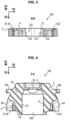
figures 1 ,3 et 4 sont des vues schématiques en coupe verticale suivant un plan de coupe vertical A-A, allant de la première à la deuxième armature, et des deuxièmes plans de coupe B-B et C-C verticaux perpendiculaires au plan de coupe A-A, traversant la première armature et la troisième armature, d'un support anti-vibratoire selon un premier mode de réalisation de l'invention ; - la
figure 2 est une vue schématique de dessus du support anti-vibratoire suivant le premier mode de réalisation de l'invention ; - les
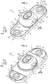
figures 6 et8 sont des vues schématiques en perspective de dessus et de dessous du support anti-vibratoire suivant le premier mode de réalisation de l'invention ; - les
figures 5 et7 sont des vues analogues auxfigures 6 et8 , où seules ont été représentées les parties du support anti-vibratoire suivant le premier mode de réalisation de l'invention reliées par la pièce en thermoplastique, laquelle n'a pas été représentée, - les
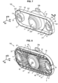
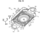
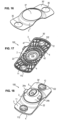
figures 9 à 15 sont des vues schématiques analogues auxfigures 1 à 6 et8 , pour un support anti-vibratoire suivant un deuxième mode de réalisation de l'invention, - la
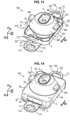
figure 16 est une vue schématique en perspective d'un renfort d'un troisième mode de réalisation du support anti-vibratoire suivant l'invention, et lesfigures 17 et 18 sont des vues schématique en perspective de dessus et de dessous de ce support.
- THE
figure 1 ,3 and 4 are schematic views in vertical section along a vertical section plane AA, going from the first to the second reinforcement, and of the second vertical section planes BB and CC perpendicular to the section plane AA, crossing the first reinforcement and the third reinforcement, an anti-vibration support according to a first embodiment of the invention; - there
picture 2 - THE
figure 6 And8 are schematic perspective views from above and below of the anti-vibration support according to the first embodiment of the invention; - THE
figure 5 And7 are views analogous tofigure 6 And8 , where only the parts of the anti-vibration support according to the first embodiment of the invention have been shown, connected by the thermoplastic part, which has not been shown, - THE
figures 9 to 15 are schematic views analogous to thefigures 1 to 6 And8 , for an anti-vibration support according to a second embodiment of the invention, - there
figure 16 is a schematic perspective view of a reinforcement of a third embodiment of the anti-vibration support according to the invention, and thefigures 17 and 18 are schematic perspective views from above and below of this support.
On décrit ci-dessous en référence aux figures des modes de réalisation d'un support anti-vibratoire 100 suivant l'invention. Bien entendu, le support anti-vibratoire 100 peut être différent des modes de réalisation décrits ci-dessous.Embodiments of an
Aux
Les armatures 11 et 12 doivent être fixées à une caisse de véhicule automobile, lorsque le support anti-vibratoire 100 est fixé à cette caisse.The
La première armature 11 et la deuxième armature 12 sont reliées entre elles par l'intermédiaire du corps 4 en matière thermoplastique. Le corps 4 est oblong suivant la première direction D1, appelée direction longitudinale D1.The
Le corps 4 en matière thermoplastique comporte un renfort 3 à fibres continues. Le renfort 3 peut être une pièce préfabriquée, pouvant être par exemple rigide. Les fibres continues peuvent être par exemple noyées dans un polymère pour former la pièce préfabriquée. Le positionnement du renfort 3 et/ou des fibres est agencé pour obtenir un renforcement maximal du support anti-vibratoire.The
Le renfort 3 peut être à fibres continues unidirectionnelles, ou à fibres continues multidirectionnelles, ou à fibres continues tissées ou non tissées. Le renfort 3 peut être une pièce préfabriquée à partir d'un ou plusieurs rubans composés des fibres continues et du polymère, le positionnement du ou des rubans étant agencé pour obtenir un renforcement maximal du support anti-vibratoire.The
Le renfort 3 peut avoir toute forme.The
Le renfort 3 peut avoir une forme annulaire, ou une forme de boucle, ou une forme oblongue, ou une forme courbe, ou une forme tridimensionnelle, ou une forme surfacique (de faible épaisseur), ou autres.The
Le renfort 3 entoure les première et deuxième surfaces 112 et 122 à distance de celles-ci, par exemple autour de la direction D2 verticale.The
On décrit ci-dessous en référence aux
Suivant un mode de réalisation, représenté aux
Suivant un mode de réalisation, représenté aux
Le corps 4 en matière thermoplastique est surmoulé contre au moins une partie d'au moins une surface du renfort 3, contre les première et deuxième surfaces 112 et 122 et contre au moins une surface d'au moins une pièce 2 en élastomère.The
Le renfort 3 peut être partiellement ou entièrement noyé dans le corps 4 en matière thermoplastique. Dans les modes de réalisation représenté aux
Le renfort 3 permet de renforcer, notamment horizontalement, la tenue mécanique globale du support anti-vibratoire, notamment entre la première armature 11 et la deuxième armature 12.The
Suivant un mode de réalisation, par exemple la boucle 30 du renfort 3 s'étend suivant un sens SE d'enroulement sensiblement horizontal autour de la deuxième direction D2 sensiblement verticale. Les fibres continues de la boucle 30 du renfort 3 s'étendent dans le sens SE d'enroulement sensiblement horizontal autour de la deuxième direction D2 sensiblement verticale. Le renfort 3 est par exemple une boucle plate 30 à section transversale rectangulaire ayant une plus grande hauteur suivant la direction D2 sensiblement verticale que suivant son épaisseur transversale à cette direction D2.According to one embodiment, for example the
Suivant un mode de réalisation, par exemple le renfort 3 peut être préfabriqué par agencement de ruban(s) de toute forme, par exemple par enroulement d'un ruban en lesdites fibres continues unidirectionnelles noyées dans le polymère et s'étendant dans le sens SE d'enroulement pour adhériser plusieurs couches du ruban en épaisseur ou en largeur (la largeur du renfort 3 étant suivant la direction D2). Le renfort est préfabriqué à part des autres parties du support anti-vibratoire 100. Les fibres peuvent être par exemple en carbone ou en fibres de verre ou autres.According to one embodiment, for example the
La pièce 2 en élastomère est située entre la troisième armature métallique 5 et le corps 4 en matière thermoplastique. La troisième armature métallique 5 est fixée à la pièce 2 en élastomère, directement ou indirectement à celle-ci. La troisième armature métallique 5 sert d'interface avec une partie vibrante du véhicule automobile. Cette partie vibrante peut être un moteur ou autres, auquel cas le support anti-vibratoire 100 est un support moteur. Par exemple, la troisième armature métallique 5 est destinée à la suspension d'un moteur de propulsion du véhicule automobile, notamment d'un moteur à combustion interne (par exemple à essence ou diesel).The
La pièce 2 en élastomère est une pièce d'amortissement de vibrations mécaniques. La pièce 2 en élastomère sert à soutenir l'armature 5 à distance du corps 4 thermoplastique et/ou à distance des armatures 1 et 2 suivant la direction D2. Ainsi, les vibrations mécaniques transmises à la troisième armature métallique 5 par la partie vibrante, lorsque la partie vibrante est fixée à cette troisième armature 5, sont amorties par la pièce 2 en élastomère par rapport aux armatures 11 et 12 lorsqu'elles sont dans leur position de fixation à la caisse du véhicule automobile. La caisse du véhicule automobile peut comporter des première et deuxième pièces de fixation (non représentées) sur lesquelles sont fixées respectivement les première et deuxième armatures 11 et 12, ces première et deuxième pièces de fixation de la caisse étant distantes l'une de l'autre suivant au moins la première direction D1 (pouvant être la direction D1 longitudinale du véhicule, allant de l'arrière vers l'avant) et définissant entre elles un passage dans la direction D2 sensiblement verticale.The
Le renfort 3 s'oppose au fait que la deuxième armature 12 s'écarte de la première armature 11 dans la direction D1 les séparant, qui est une direction longitudinale du véhicule, dirigée de l'arrière vers l'avant, et assure une meilleure résistance du support anti-vibratoire. Notamment, dans le cas d'un support anti-vibratoire, ce support anti-vibratoire passe avec succès les essais de collision frontale du véhicule.The
La pièce 2 en élastomère est par exemple en caoutchouc. La troisième armature 5 peut être composée d'une seule matière métallique ou être en un bi-composant métal-thermoplastique. La pièce 2 en élastomère peut également contenir une partie hydraulique.The
Suivant un mode de réalisation, le corps 4 en matière thermoplastique peut comporter par exemple une première ouverture 43 permettant la traversée dans la deuxième direction D2 sensiblement verticale. Cette première ouverture 43 est entourée par le renfort 3 ou par la boucle 30 du renfort 3. La pièce 2 en élastomère possède une portion intérieure 21 ayant elle-même une deuxième ouverture 23 permettant la traversée dans la deuxième direction D2. La deuxième ouverture 23 est située sous la troisième armature métallique 5 dans la deuxième direction D2. Un passage 230 ouvert vers le bas dans la direction verticale D2 sous l'armature 5 est délimité par l'ouverture 23. Ce passage 230 est entouré par l'ouverture 43. En haut de l'ouverture 23, la portion supérieure 22 du corps 2 en élastomère entoure la troisième armature 5 autour de la direction D2.According to one embodiment, the
Dans les modes de réalisation représentés aux
Ainsi, on peut faire passer verticalement (par la deuxième direction D2) dans la deuxième ouverture 23 une ou plusieurs broches servant à la fixation de la troisième armature métallique 5 à la partie vibrante, cette fixation se faisant par le bas de la troisième armature 5, la partie vibrante étant alors suspendue sous le support anti-vibratoire 100.Thus, it is possible to pass vertically (by the second direction D2) in the
Dans les modes de réalisation représentés aux
Dans les modes de réalisation représentés aux
Ainsi, le corps 4 en matière thermoplastique n'est pas fragilisé par les ouvertures 23 et 43 mais est renforcé par le renfort 3.Thus, the
Dans les modes de réalisation représentés aux
Dans les modes de réalisation représentés aux
Ainsi, en cas de vibrations mécaniques envoyées par la partie vibrante à la troisième armature métallique 5 dans le sens vertical, les excroissances 24a et 24b butent vers le bas pour amortir ces vibrations.Thus, in the event of mechanical vibrations sent by the vibrating part to the
Les excroissances 24a et 24b sont par exemple situées au-dessus d'une partie du renfort 3 suivant la direction D2. On assure ainsi une meilleure rigidité du support anti-vibratoire 100.The
Dans les modes de réalisation représentés aux
Dans les modes de réalisation représentés aux
Dans les modes de réalisation représentés aux
Dans les modes de réalisation représentés aux
Dans les modes de réalisation représentés aux
Dans le premier mode de réalisation représenté aux
Dans le deuxième mode de réalisation représenté aux
Claims (15)
- Anti-vibration support (100), havingfirst and second metallic reinforcements (11, 12) and a third reinforcement (5), which are accessible from the outside and are at a distance from one another,at least one elastomer component (2),the support also having a body (4) made of thermoplastic material,the first and second reinforcements (11, 12) being remote from one another in a first, substantially horizontal direction (D1), being intended to be fastened to a motor vehicle bodyshell and being connected to each other via the body (4) made of thermoplastic material,the body (4) made of thermoplastic material being overmoulded with respect to first and second surfaces (112, 122) of the first and second reinforcements (11, 12) and with respect to at least one surface of the elastomer component (2) for supporting the third reinforcement (5) intended for the suspension of a vibrating part of the vehicle, for the damping and filtering of mechanical vibrations between the bodyshell and the vibrating part,characterized in thatthe third reinforcement (5) is metallic or made from a metal-thermoplastic two-part substance,the body (4) made of thermoplastic material has at least one reinforcer (3) with continuous fibres, which is a prefabricated component and is separate from the reinforcements, so as to reinforce the mechanical integrity of the anti-vibration support,the body (4) made of thermoplastic material is overmoulded with respect to at least one part of at least one surface of the reinforcer (3),the reinforcer (3) surrounds the first and second surfaces (112, 122) at least in the first, substantially horizontal direction (D1).
- Anti-vibration support according to Claim 1, characterized in that the body (4) made of thermoplastic material has a first through-opening (43) in a second, substantially vertical direction (D2), the first opening (43) being surrounded by the reinforcer (3),an inner portion (21) of the elastomer component (2) itself having a second through-opening (23) in the second direction (D2),a passage (230) that is open towards the bottom in the second direction (D2) beneath the third reinforcement (5) being delimited by the second opening (23), the passage (230) being surrounded by the first opening (43).
- Anti-vibration support according to Claim 2, characterized in that the third reinforcement (5) has at least one third through-opening (53) in the second direction (D2), situated above the second opening (23) in the second direction (D2).
- Anti-vibration support according to Claim 2 or 3, characterized in that the reinforcer (3) extends in a substantially horizontal direction of winding (SE) around the second direction (D2), and has continuous unidirectional fibres extending in the direction of winding (SE) and embedded in a polymer so as to form the prefabricated component having the shape of a loop (30).
- Anti-vibration support according to any one of Claims 2 to 4, characterized in that the second opening (23) in the elastomer component (2) passes through the first opening (43) in the body (4) made of thermoplastic material in the second direction (D2).
- Anti-vibration support according to any one of Claims 2 to 5, characterized in that the reinforcer (3) extends around the second direction (D2) and surrounds the first opening (43) and the second opening (23).
- Anti-vibration support according to any one of the preceding claims, characterized in that the elastomer component (2) has an upper portion (22) covering a part (410) of the upper surface (41) of the body (4) made of thermoplastic material and supporting the third reinforcement (5).
- Anti-vibration support according to any one of the preceding claims, characterized in that the first and second surfaces (112, 122) are vertical.
- Anti-vibration support according to any one of the preceding claims, characterized in that the elastomer component (2) has a first abutment protrusion (24a) and a second abutment protrusion (24b), which are intended to downwardly abut other corresponding parts of the anti-vibration support and are remote from one another transversely to a second, substantially vertical direction (D2).
- Anti-vibration support according to any one of the preceding claims, characterized in that the third reinforcement (5) extends in a second, substantially vertical direction (D2) between a first, lower level (N1) and a second, upper level (N2),the body (4) made of thermoplastic material extends in the second, substantially vertical direction (D2) between a third, lower level (N3) and a fourth, upper level (N4),the first, lower level (N1) being situated above the fourth, upper level (N4).
- Anti-vibration support according to any one of the preceding claims, characterized in that the first and second reinforcements (11, 12) respectively have first and second holes (113, 123), which allow them to be passed through in a second, substantially vertical direction (D2) for the fastening to the motor vehicle bodyshell and are delimited by, respectively, third and fourth free surfaces (114, 124), which are accessible from the outside and connected to the first and second surfaces (112, 122).
- Anti-vibration support according to Claim 11, characterized in that the first and second reinforcements (11, 12) are formed by, respectively, first and second rings (11, 12) delimiting the first and second holes (113, 123), the third and fourth free surfaces (114, 124) being situated on the inside of the first and second rings (11, 12), the first and second surfaces (112, 122) being situated on the outside of the first and second rings (11, 12).
- Anti-vibration support according to Claim 11, characterized in that the third and fourth surfaces (114, 124) and the first and second holes (1113, 1213) are situated on, respectively, first and second external fastening tabs (115, 125) projecting towards the outside of the body (4) in the first, substantially horizontal direction (D1).
- Anti-vibration support according to Claim 13, characterized in that the first and second tabs (115, 125) are horizontal and elbowed with respect to the first and second vertical surfaces (112, 122).
- Motor vehicle, having a bodyshell, an engine mounted on the bodyshell and at least one anti-vibration support according to any one of the preceding claims, the first and second reinforcements (11, 12) being fastened to the bodyshell, the third reinforcement (5) being fastened to the engine situated beneath the anti-vibration support (100).
Applications Claiming Priority (1)
| Application Number | Priority Date | Filing Date | Title |
|---|---|---|---|
| PCT/FR2016/052578 WO2018065677A1 (en) | 2016-10-06 | 2016-10-06 | Anti-vibratory support for a motor vehicle and motor vehicle equipped with same |
Publications (2)
| Publication Number | Publication Date |
|---|---|
| EP3523552A1 EP3523552A1 (en) | 2019-08-14 |
| EP3523552B1 true EP3523552B1 (en) | 2023-04-05 |
Family
ID=57218924
Family Applications (1)
| Application Number | Title | Priority Date | Filing Date |
|---|---|---|---|
| EP16788736.3A Active EP3523552B1 (en) | 2016-10-06 | 2016-10-06 | Anti-vibratory support for a motor vehicle and motor vehicle equipped with same |
Country Status (4)
| Country | Link |
|---|---|
| US (1) | US10718400B2 (en) |
| EP (1) | EP3523552B1 (en) |
| CN (1) | CN109790892B (en) |
| WO (1) | WO2018065677A1 (en) |
Families Citing this family (3)
| Publication number | Priority date | Publication date | Assignee | Title |
|---|---|---|---|---|
| DE102019000696B4 (en) * | 2019-01-31 | 2025-06-18 | Süddeutsche Gelenkscheibenfabrik Gesellschaft mit beschränkter Haftung & Co. KG. | Elastic bearing |
| KR102460113B1 (en) * | 2020-09-09 | 2022-10-27 | 한국교통대학교산학협력단 | Anti vibration device and container including same |
| FR3119654B1 (en) * | 2021-02-09 | 2023-05-26 | Hutchinson | Anti-vibration support and vehicle comprising such an anti-vibration support. |
Family Cites Families (15)
| Publication number | Priority date | Publication date | Assignee | Title |
|---|---|---|---|---|
| US3243239A (en) * | 1962-08-24 | 1966-03-29 | Southwest Products Co | Rubber-supported engine mount bearing |
| US4067525A (en) * | 1976-11-18 | 1978-01-10 | Bushings, Inc. | Resilient mounting |
| DE3805763A1 (en) * | 1988-02-24 | 1989-09-07 | Daimler Benz Ag | HYDRAULIC DAMPING RUBBER BEARING |
| JP2657319B2 (en) * | 1989-08-08 | 1997-09-24 | 本田技研工業株式会社 | Automobile power unit support device |
| US5704598A (en) | 1995-09-12 | 1998-01-06 | Bridgestone Corporation | Vibration isolating apparatus |
| JP3949549B2 (en) * | 2002-09-06 | 2007-07-25 | 本田技研工業株式会社 | Vehicle transmission mount structure |
| JP2004100789A (en) * | 2002-09-06 | 2004-04-02 | Honda Motor Co Ltd | Vehicle power source mounting structure |
| DE20307898U1 (en) * | 2003-05-19 | 2003-07-24 | Basf Ag, 67063 Ludwigshafen | Spring based on a cylindrical damping element made of a material derived from polyisocyanate polyaddition products has a circumferential base section and a head section with an end shaped as a convex lens |
| JP4060309B2 (en) * | 2004-11-04 | 2008-03-12 | 本田技研工業株式会社 | Vibration isolator for vehicle |
| JP4276185B2 (en) * | 2005-01-26 | 2009-06-10 | 本田技研工業株式会社 | Body front structure |
| JP4930576B2 (en) * | 2009-02-27 | 2012-05-16 | 日産自動車株式会社 | Motor support structure |
| DE102010015882B4 (en) * | 2010-03-09 | 2024-08-29 | Contitech Vibration Control Gmbh | Bearing for a motor vehicle |
| CN201934559U (en) * | 2010-12-21 | 2011-08-17 | 宁波泛亚汽车部件有限公司 | Shockproof rubber bushing |
| DE102011006917A1 (en) * | 2011-04-07 | 2012-10-31 | Bayerische Motoren Werke Aktiengesellschaft | Engine supporting bracket for motor vehicle, has section made of base material and another section made of reinforcing material, where reinforcing material is connected with base material in form-fit and force-fit manner |
| JP6002607B2 (en) * | 2013-03-12 | 2016-10-05 | 住友理工株式会社 | Vibration isolator |
-
2016
- 2016-10-06 WO PCT/FR2016/052578 patent/WO2018065677A1/en not_active Ceased
- 2016-10-06 EP EP16788736.3A patent/EP3523552B1/en active Active
- 2016-10-06 US US16/339,237 patent/US10718400B2/en active Active
- 2016-10-06 CN CN201680089886.9A patent/CN109790892B/en active Active
Also Published As
| Publication number | Publication date |
|---|---|
| CN109790892B (en) | 2021-01-12 |
| US10718400B2 (en) | 2020-07-21 |
| WO2018065677A1 (en) | 2018-04-12 |
| US20190285134A1 (en) | 2019-09-19 |
| EP3523552A1 (en) | 2019-08-14 |
| CN109790892A (en) | 2019-05-21 |
Similar Documents
| Publication | Publication Date | Title |
|---|---|---|
| EP1816371A1 (en) | Hydraulic antivibration support and its manufacturing process | |
| EP1217249B1 (en) | Anti-vibration bush and motor vehicle comprising said bush | |
| EP1390639B1 (en) | Anti-vibration mount and production method for same | |
| WO2000058144A1 (en) | Combined automotive bumper skin/ under-engine fairing | |
| EP3523552B1 (en) | Anti-vibratory support for a motor vehicle and motor vehicle equipped with same | |
| FR3093071A1 (en) | MOTORCYCLE SEAT RAIL | |
| EP2266829B1 (en) | Vibration isolator with limited movement | |
| EP2436579B1 (en) | Dashboard crossmember unit for an automobile. | |
| WO2009001016A2 (en) | Hinge for bonnet of motor vehicle | |
| EP2282076B1 (en) | Anti-vibration device for a vehicle and vehicle including such a device | |
| EP3423733B1 (en) | Vibration damping device between a first vibrating element and a second element | |
| EP3126209B1 (en) | Reinforced vehicle structure | |
| WO2015090989A1 (en) | Assembly comprising a dashboard cross-member for a motor vehicle and two side supports for securing the cross-member to the body of the vehicle | |
| FR2944769A3 (en) | FIXING PLATE FOR MOTOR VEHICLE RADIATOR | |
| FR3068668B1 (en) | MOTOR POWERTRAIN FOR MOTOR POWER MACHINE SUSPENDED AT HYBRID TRAVERSE | |
| WO2019202230A1 (en) | Frame horn for a cradle of a motor vehicle | |
| FR3120046A1 (en) | Motor vehicle shock absorber assembly | |
| FR3057235B1 (en) | REINFORCING ELEMENT FOR A PARCLOSE FLOOR OF A FLOOR OF A BODY STRUCTURE OF A MOTOR VEHICLE | |
| WO2015189504A1 (en) | Arrangement of a dashboard trim element of a motor vehicle on a supporting element of said dashboard | |
| FR3095374A1 (en) | CONNECTION TO SCREEDS FOR FIXING AN ELASTIC JOINT OF A SUSPENSION TRIANGLE | |
| EP2176093B1 (en) | Bumper shield | |
| FR3083833A1 (en) | ASSEMBLY OF A MEMBER OF EXPANDED POLYMER MATERIAL AND A PART OF A MOTOR VEHICLE | |
| EP1645492B1 (en) | Fastening assembly of a wheel protector to the structure of a motor vehicle, with means for suppressing vibrations | |
| FR3147758A1 (en) | Motor vehicle front bumper skin and manufacturing method | |
| EP4538151A1 (en) | Arrangement for a motor vehicle comprising a locking assembly for a cover and a supporting frame element |
Legal Events
| Date | Code | Title | Description |
|---|---|---|---|
| STAA | Information on the status of an ep patent application or granted ep patent |
Free format text: STATUS: UNKNOWN |
|
| STAA | Information on the status of an ep patent application or granted ep patent |
Free format text: STATUS: THE INTERNATIONAL PUBLICATION HAS BEEN MADE |
|
| PUAI | Public reference made under article 153(3) epc to a published international application that has entered the european phase |
Free format text: ORIGINAL CODE: 0009012 |
|
| STAA | Information on the status of an ep patent application or granted ep patent |
Free format text: STATUS: REQUEST FOR EXAMINATION WAS MADE |
|
| 17P | Request for examination filed |
Effective date: 20190321 |
|
| AK | Designated contracting states |
Kind code of ref document: A1 Designated state(s): AL AT BE BG CH CY CZ DE DK EE ES FI FR GB GR HR HU IE IS IT LI LT LU LV MC MK MT NL NO PL PT RO RS SE SI SK SM TR |
|
| AX | Request for extension of the european patent |
Extension state: BA ME |
|
| DAX | Request for extension of the european patent (deleted) | ||
| RAV | Requested validation state of the european patent: fee paid |
Extension state: MA Effective date: 20190321 |
|
| RAP1 | Party data changed (applicant data changed or rights of an application transferred) |
Owner name: CONTITECH VIBRATION CONTROL GMBH |
|
| GRAP | Despatch of communication of intention to grant a patent |
Free format text: ORIGINAL CODE: EPIDOSNIGR1 |
|
| STAA | Information on the status of an ep patent application or granted ep patent |
Free format text: STATUS: GRANT OF PATENT IS INTENDED |
|
| INTG | Intention to grant announced |
Effective date: 20221214 |
|
| GRAS | Grant fee paid |
Free format text: ORIGINAL CODE: EPIDOSNIGR3 |
|
| GRAA | (expected) grant |
Free format text: ORIGINAL CODE: 0009210 |
|
| STAA | Information on the status of an ep patent application or granted ep patent |
Free format text: STATUS: THE PATENT HAS BEEN GRANTED |
|
| AK | Designated contracting states |
Kind code of ref document: B1 Designated state(s): AL AT BE BG CH CY CZ DE DK EE ES FI FR GB GR HR HU IE IS IT LI LT LU LV MC MK MT NL NO PL PT RO RS SE SI SK SM TR |
|
| REG | Reference to a national code |
Ref country code: GB Ref legal event code: FG4D Free format text: NOT ENGLISH |
|
| REG | Reference to a national code |
Ref country code: CH Ref legal event code: EP |
|
| REG | Reference to a national code |
Ref country code: AT Ref legal event code: REF Ref document number: 1558446 Country of ref document: AT Kind code of ref document: T Effective date: 20230415 |
|
| REG | Reference to a national code |
Ref country code: DE Ref legal event code: R096 Ref document number: 602016078675 Country of ref document: DE |
|
| REG | Reference to a national code |
Ref country code: IE Ref legal event code: FG4D Free format text: LANGUAGE OF EP DOCUMENT: FRENCH |
|
| P01 | Opt-out of the competence of the unified patent court (upc) registered |
Effective date: 20230602 |
|
| REG | Reference to a national code |
Ref country code: LT Ref legal event code: MG9D |
|
| REG | Reference to a national code |
Ref country code: NL Ref legal event code: MP Effective date: 20230405 |
|
| REG | Reference to a national code |
Ref country code: AT Ref legal event code: MK05 Ref document number: 1558446 Country of ref document: AT Kind code of ref document: T Effective date: 20230405 |
|
| PG25 | Lapsed in a contracting state [announced via postgrant information from national office to epo] |
Ref country code: NL Free format text: LAPSE BECAUSE OF FAILURE TO SUBMIT A TRANSLATION OF THE DESCRIPTION OR TO PAY THE FEE WITHIN THE PRESCRIBED TIME-LIMIT Effective date: 20230405 |
|
| PG25 | Lapsed in a contracting state [announced via postgrant information from national office to epo] |
Ref country code: SE Free format text: LAPSE BECAUSE OF FAILURE TO SUBMIT A TRANSLATION OF THE DESCRIPTION OR TO PAY THE FEE WITHIN THE PRESCRIBED TIME-LIMIT Effective date: 20230405 Ref country code: PT Free format text: LAPSE BECAUSE OF FAILURE TO SUBMIT A TRANSLATION OF THE DESCRIPTION OR TO PAY THE FEE WITHIN THE PRESCRIBED TIME-LIMIT Effective date: 20230807 Ref country code: NO Free format text: LAPSE BECAUSE OF FAILURE TO SUBMIT A TRANSLATION OF THE DESCRIPTION OR TO PAY THE FEE WITHIN THE PRESCRIBED TIME-LIMIT Effective date: 20230705 Ref country code: ES Free format text: LAPSE BECAUSE OF FAILURE TO SUBMIT A TRANSLATION OF THE DESCRIPTION OR TO PAY THE FEE WITHIN THE PRESCRIBED TIME-LIMIT Effective date: 20230405 Ref country code: AT Free format text: LAPSE BECAUSE OF FAILURE TO SUBMIT A TRANSLATION OF THE DESCRIPTION OR TO PAY THE FEE WITHIN THE PRESCRIBED TIME-LIMIT Effective date: 20230405 |
|
| PG25 | Lapsed in a contracting state [announced via postgrant information from national office to epo] |
Ref country code: RS Free format text: LAPSE BECAUSE OF FAILURE TO SUBMIT A TRANSLATION OF THE DESCRIPTION OR TO PAY THE FEE WITHIN THE PRESCRIBED TIME-LIMIT Effective date: 20230405 Ref country code: PL Free format text: LAPSE BECAUSE OF FAILURE TO SUBMIT A TRANSLATION OF THE DESCRIPTION OR TO PAY THE FEE WITHIN THE PRESCRIBED TIME-LIMIT Effective date: 20230405 Ref country code: LV Free format text: LAPSE BECAUSE OF FAILURE TO SUBMIT A TRANSLATION OF THE DESCRIPTION OR TO PAY THE FEE WITHIN THE PRESCRIBED TIME-LIMIT Effective date: 20230405 Ref country code: LT Free format text: LAPSE BECAUSE OF FAILURE TO SUBMIT A TRANSLATION OF THE DESCRIPTION OR TO PAY THE FEE WITHIN THE PRESCRIBED TIME-LIMIT Effective date: 20230405 Ref country code: IS Free format text: LAPSE BECAUSE OF FAILURE TO SUBMIT A TRANSLATION OF THE DESCRIPTION OR TO PAY THE FEE WITHIN THE PRESCRIBED TIME-LIMIT Effective date: 20230805 Ref country code: HR Free format text: LAPSE BECAUSE OF FAILURE TO SUBMIT A TRANSLATION OF THE DESCRIPTION OR TO PAY THE FEE WITHIN THE PRESCRIBED TIME-LIMIT Effective date: 20230405 Ref country code: GR Free format text: LAPSE BECAUSE OF FAILURE TO SUBMIT A TRANSLATION OF THE DESCRIPTION OR TO PAY THE FEE WITHIN THE PRESCRIBED TIME-LIMIT Effective date: 20230706 Ref country code: AL Free format text: LAPSE BECAUSE OF FAILURE TO SUBMIT A TRANSLATION OF THE DESCRIPTION OR TO PAY THE FEE WITHIN THE PRESCRIBED TIME-LIMIT Effective date: 20230405 |
|
| PG25 | Lapsed in a contracting state [announced via postgrant information from national office to epo] |
Ref country code: FI Free format text: LAPSE BECAUSE OF FAILURE TO SUBMIT A TRANSLATION OF THE DESCRIPTION OR TO PAY THE FEE WITHIN THE PRESCRIBED TIME-LIMIT Effective date: 20230405 |
|
| REG | Reference to a national code |
Ref country code: DE Ref legal event code: R097 Ref document number: 602016078675 Country of ref document: DE |
|
| PG25 | Lapsed in a contracting state [announced via postgrant information from national office to epo] |
Ref country code: SK Free format text: LAPSE BECAUSE OF FAILURE TO SUBMIT A TRANSLATION OF THE DESCRIPTION OR TO PAY THE FEE WITHIN THE PRESCRIBED TIME-LIMIT Effective date: 20230405 |
|
| PG25 | Lapsed in a contracting state [announced via postgrant information from national office to epo] |
Ref country code: SM Free format text: LAPSE BECAUSE OF FAILURE TO SUBMIT A TRANSLATION OF THE DESCRIPTION OR TO PAY THE FEE WITHIN THE PRESCRIBED TIME-LIMIT Effective date: 20230405 Ref country code: SK Free format text: LAPSE BECAUSE OF FAILURE TO SUBMIT A TRANSLATION OF THE DESCRIPTION OR TO PAY THE FEE WITHIN THE PRESCRIBED TIME-LIMIT Effective date: 20230405 Ref country code: RO Free format text: LAPSE BECAUSE OF FAILURE TO SUBMIT A TRANSLATION OF THE DESCRIPTION OR TO PAY THE FEE WITHIN THE PRESCRIBED TIME-LIMIT Effective date: 20230405 Ref country code: EE Free format text: LAPSE BECAUSE OF FAILURE TO SUBMIT A TRANSLATION OF THE DESCRIPTION OR TO PAY THE FEE WITHIN THE PRESCRIBED TIME-LIMIT Effective date: 20230405 Ref country code: DK Free format text: LAPSE BECAUSE OF FAILURE TO SUBMIT A TRANSLATION OF THE DESCRIPTION OR TO PAY THE FEE WITHIN THE PRESCRIBED TIME-LIMIT Effective date: 20230405 Ref country code: CZ Free format text: LAPSE BECAUSE OF FAILURE TO SUBMIT A TRANSLATION OF THE DESCRIPTION OR TO PAY THE FEE WITHIN THE PRESCRIBED TIME-LIMIT Effective date: 20230405 |
|
| PLBE | No opposition filed within time limit |
Free format text: ORIGINAL CODE: 0009261 |
|
| STAA | Information on the status of an ep patent application or granted ep patent |
Free format text: STATUS: NO OPPOSITION FILED WITHIN TIME LIMIT |
|
| REG | Reference to a national code |
Ref country code: DE Ref legal event code: R081 Ref document number: 602016078675 Country of ref document: DE Owner name: CONTITECH VIBRATION CONTROL GMBH, DE Free format text: FORMER OWNER: CONTITECH VIBRATION CONTROL GMBH, 30165 HANNOVER, DE |
|
| 26N | No opposition filed |
Effective date: 20240108 |
|
| PG25 | Lapsed in a contracting state [announced via postgrant information from national office to epo] |
Ref country code: SI Free format text: LAPSE BECAUSE OF FAILURE TO SUBMIT A TRANSLATION OF THE DESCRIPTION OR TO PAY THE FEE WITHIN THE PRESCRIBED TIME-LIMIT Effective date: 20230405 |
|
| PG25 | Lapsed in a contracting state [announced via postgrant information from national office to epo] |
Ref country code: SI Free format text: LAPSE BECAUSE OF FAILURE TO SUBMIT A TRANSLATION OF THE DESCRIPTION OR TO PAY THE FEE WITHIN THE PRESCRIBED TIME-LIMIT Effective date: 20230405 Ref country code: IT Free format text: LAPSE BECAUSE OF FAILURE TO SUBMIT A TRANSLATION OF THE DESCRIPTION OR TO PAY THE FEE WITHIN THE PRESCRIBED TIME-LIMIT Effective date: 20230405 Ref country code: MC Free format text: LAPSE BECAUSE OF FAILURE TO SUBMIT A TRANSLATION OF THE DESCRIPTION OR TO PAY THE FEE WITHIN THE PRESCRIBED TIME-LIMIT Effective date: 20230405 |
|
| REG | Reference to a national code |
Ref country code: CH Ref legal event code: PL |
|
| REG | Reference to a national code |
Ref country code: BE Ref legal event code: MM Effective date: 20231031 |
|
| PG25 | Lapsed in a contracting state [announced via postgrant information from national office to epo] |
Ref country code: LU Free format text: LAPSE BECAUSE OF NON-PAYMENT OF DUE FEES Effective date: 20231006 |
|
| PG25 | Lapsed in a contracting state [announced via postgrant information from national office to epo] |
Ref country code: LU Free format text: LAPSE BECAUSE OF NON-PAYMENT OF DUE FEES Effective date: 20231006 |
|
| PG25 | Lapsed in a contracting state [announced via postgrant information from national office to epo] |
Ref country code: CH Free format text: LAPSE BECAUSE OF NON-PAYMENT OF DUE FEES Effective date: 20231031 |
|
| PG25 | Lapsed in a contracting state [announced via postgrant information from national office to epo] |
Ref country code: CH Free format text: LAPSE BECAUSE OF NON-PAYMENT OF DUE FEES Effective date: 20231031 |
|
| PG25 | Lapsed in a contracting state [announced via postgrant information from national office to epo] |
Ref country code: BE Free format text: LAPSE BECAUSE OF NON-PAYMENT OF DUE FEES Effective date: 20231031 |
|
| PG25 | Lapsed in a contracting state [announced via postgrant information from national office to epo] |
Ref country code: IE Free format text: LAPSE BECAUSE OF NON-PAYMENT OF DUE FEES Effective date: 20231006 |
|
| PG25 | Lapsed in a contracting state [announced via postgrant information from national office to epo] |
Ref country code: IE Free format text: LAPSE BECAUSE OF NON-PAYMENT OF DUE FEES Effective date: 20231006 |
|
| PG25 | Lapsed in a contracting state [announced via postgrant information from national office to epo] |
Ref country code: BG Free format text: LAPSE BECAUSE OF FAILURE TO SUBMIT A TRANSLATION OF THE DESCRIPTION OR TO PAY THE FEE WITHIN THE PRESCRIBED TIME-LIMIT Effective date: 20230405 |
|
| PG25 | Lapsed in a contracting state [announced via postgrant information from national office to epo] |
Ref country code: BG Free format text: LAPSE BECAUSE OF FAILURE TO SUBMIT A TRANSLATION OF THE DESCRIPTION OR TO PAY THE FEE WITHIN THE PRESCRIBED TIME-LIMIT Effective date: 20230405 |
|
| PG25 | Lapsed in a contracting state [announced via postgrant information from national office to epo] |
Ref country code: CY Free format text: LAPSE BECAUSE OF FAILURE TO SUBMIT A TRANSLATION OF THE DESCRIPTION OR TO PAY THE FEE WITHIN THE PRESCRIBED TIME-LIMIT; INVALID AB INITIO Effective date: 20161006 |
|
| PG25 | Lapsed in a contracting state [announced via postgrant information from national office to epo] |
Ref country code: HU Free format text: LAPSE BECAUSE OF FAILURE TO SUBMIT A TRANSLATION OF THE DESCRIPTION OR TO PAY THE FEE WITHIN THE PRESCRIBED TIME-LIMIT; INVALID AB INITIO Effective date: 20161006 |
|
| VS25 | Lapsed in a validation state [announced via postgrant information from nat. office to epo] |
Ref country code: MA Free format text: FAILURE TO ELECT DOMICILE IN THE NATIONAL COUNTRY Effective date: 20230706 |
|
| PG25 | Lapsed in a contracting state [announced via postgrant information from national office to epo] |
Ref country code: TR Free format text: LAPSE BECAUSE OF FAILURE TO SUBMIT A TRANSLATION OF THE DESCRIPTION OR TO PAY THE FEE WITHIN THE PRESCRIBED TIME-LIMIT Effective date: 20230405 |
|
| PGFP | Annual fee paid to national office [announced via postgrant information from national office to epo] |
Ref country code: DE Payment date: 20251020 Year of fee payment: 10 |
|
| PGFP | Annual fee paid to national office [announced via postgrant information from national office to epo] |
Ref country code: GB Payment date: 20251022 Year of fee payment: 10 |
|
| PGFP | Annual fee paid to national office [announced via postgrant information from national office to epo] |
Ref country code: FR Payment date: 20251027 Year of fee payment: 10 |