EP1216175B1 - Verfahren zur erfassung und auswertung von fahrdynamischen zuständen eines kraftfahrzeugs - Google Patents
Verfahren zur erfassung und auswertung von fahrdynamischen zuständen eines kraftfahrzeugs Download PDFInfo
- Publication number
- EP1216175B1 EP1216175B1 EP00964171A EP00964171A EP1216175B1 EP 1216175 B1 EP1216175 B1 EP 1216175B1 EP 00964171 A EP00964171 A EP 00964171A EP 00964171 A EP00964171 A EP 00964171A EP 1216175 B1 EP1216175 B1 EP 1216175B1
- Authority
- EP
- European Patent Office
- Prior art keywords
- amplitude
- output signal
- nominal value
- signal
- tire
- Prior art date
- Legal status (The legal status is an assumption and is not a legal conclusion. Google has not performed a legal analysis and makes no representation as to the accuracy of the status listed.)
- Expired - Lifetime
Links
- 238000000034 method Methods 0.000 title claims description 15
- 230000001419 dependent effect Effects 0.000 claims description 9
- 230000000694 effects Effects 0.000 claims description 3
- 230000001133 acceleration Effects 0.000 description 8
- 230000003750 conditioning effect Effects 0.000 description 4
- 230000002596 correlated effect Effects 0.000 description 3
- 238000011156 evaluation Methods 0.000 description 3
- 230000006978 adaptation Effects 0.000 description 2
- 238000001514 detection method Methods 0.000 description 2
- 239000000725 suspension Substances 0.000 description 2
- 230000000875 corresponding effect Effects 0.000 description 1
- 238000013461 design Methods 0.000 description 1
- 230000005021 gait Effects 0.000 description 1
- 238000004519 manufacturing process Methods 0.000 description 1
- 238000013507 mapping Methods 0.000 description 1
- 238000005259 measurement Methods 0.000 description 1
- 238000012545 processing Methods 0.000 description 1
- 230000001105 regulatory effect Effects 0.000 description 1
Images

Classifications
-
- G—PHYSICS
- G01—MEASURING; TESTING
- G01L—MEASURING FORCE, STRESS, TORQUE, WORK, MECHANICAL POWER, MECHANICAL EFFICIENCY, OR FLUID PRESSURE
- G01L5/00—Apparatus for, or methods of, measuring force, work, mechanical power, or torque, specially adapted for specific purposes
- G01L5/20—Apparatus for, or methods of, measuring force, work, mechanical power, or torque, specially adapted for specific purposes for measuring wheel side-thrust
-
- G—PHYSICS
- G01—MEASURING; TESTING
- G01D—MEASURING NOT SPECIALLY ADAPTED FOR A SPECIFIC VARIABLE; ARRANGEMENTS FOR MEASURING TWO OR MORE VARIABLES NOT COVERED IN A SINGLE OTHER SUBCLASS; TARIFF METERING APPARATUS; MEASURING OR TESTING NOT OTHERWISE PROVIDED FOR
- G01D3/00—Indicating or recording apparatus with provision for the special purposes referred to in the subgroups
- G01D3/02—Indicating or recording apparatus with provision for the special purposes referred to in the subgroups with provision for altering or correcting the law of variation
- G01D3/021—Indicating or recording apparatus with provision for the special purposes referred to in the subgroups with provision for altering or correcting the law of variation using purely analogue techniques
-
- B—PERFORMING OPERATIONS; TRANSPORTING
- B60—VEHICLES IN GENERAL
- B60T—VEHICLE BRAKE CONTROL SYSTEMS OR PARTS THEREOF; BRAKE CONTROL SYSTEMS OR PARTS THEREOF, IN GENERAL; ARRANGEMENT OF BRAKING ELEMENTS ON VEHICLES IN GENERAL; PORTABLE DEVICES FOR PREVENTING UNWANTED MOVEMENT OF VEHICLES; VEHICLE MODIFICATIONS TO FACILITATE COOLING OF BRAKES
- B60T2240/00—Monitoring, detecting wheel/tyre behaviour; counteracting thereof
- B60T2240/03—Tyre sensors
Definitions
- the invention relates to a method and a control circuit for recording and evaluating dynamic driving conditions a motor vehicle by means of Radkraftsensoren, preferably with Tire sensors, as a measure of the on the wheel or the tire acting lateral forces the preset air gap between at least one rotating encoder and at least one Use the transducer.
- a tire sensor at a Deformation of the tire due to the attacking on the tire Forces a change in the phase angle and / or the amplitude between output from transducers output signals is described in WO 97/44673.
- the size of the Air gap between the encoder or in the Tire sidewall embedded magnetic areas and the e.g. active, magnetoresistive transducers form the Signals that are responsible for the assignment of the tire Lateral or transverse forces are used.
- the changes of detected by the transducer signals thus form the deformations or changes of the tire sidewall, due to the lateral forces acting on the wheels while changing the phase angle between the two on an outer and inner radius to Rotary axis of the wheel arranged transducers Defining the signal for the calculation of the longitudinal forces.
- the invention is based on the object, a reduced-error Evaluation of wheel forces, in particular by means of Tire sensors detected deformations of the rim and / or the Tire, allow.
- the invention of the air gap dependent operating point of the output signal of the Transducer or a e.g. the transducer downstream signal conditioning device independent of whose default setting is set, can be without loss at signal quality, the output signal error-reduced process as it is independent of this preset Distance between transducer and encoder is determined. It can be rims with different Einpreßtiefe, but with equal rigidity, use.
- the distance of the transducer as desired over the Resolution range can be varied without any adjustments the functional mapping between the amplitude and the Shear force are required.
- the value (nominal value) to which the output signal relates (normalized) can be.
- That of the transducer or a signal conditioning for Provided output signal is a sinusoidal AC voltage or current signal, whose nominal value at each Peak value of the half-wave (amplitude) or at each change the pole or marks of the encoder is determined when the Conditions of stationary driving are met.
- the Denomination is assigned a value that is the zero point (offset) the lateral force acting on the wheel and / or the tire reproduces.
- the lateral forces can then essentially as a function of Distance changes are determined.
- Figure 1 a and b show a control circuit 10, with two in radial distance from the axis of rotation 11 of the wheel 12 arranged on the chassis of a motor vehicle Magnetic field sensitive transducers 13, 14th connected is.
- the control circuit can be part of the transducer or a separate unit or Part of ABS (anti-lock control system), from ASR (Traction control), from ESP (Electronic Traction Control) Driving stability control system), from EHB (Electrohydraulic Brake control system), a suspension control system and / or an EMB (electro-mechanical brake) control system.
- the vehicle tire 15 has an encoder 17 with permanent magnetic areas with alternating polarity N, S on. The permanent magnetic areas N, S are in the Tire wall 18 of the wheel 12 stored.
- the measuring signal is by a sensor integrated amplified electronic circuit and into an output signal changed. In a determination unit 21, that of the Air gap 20 dependent operating point of the output signal of the Transducer 13 independent of the default setting established.
- the output signal at steady Driving behavior of the vehicle normalized to a nominal value and via means 21 the nominal value with the lateral force zero point correlated. Thereafter, there is a reproducible relationship between the change of the amplitude signal and the Change in the lateral force.
- the AC signal can be in a transducer 13 associated signal processing device in a AC signal to be transformed.
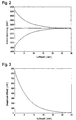
- FIGS. 3 and 4 shows the relationship between the air gap 20 and the Amplitude signal of the transducer 13, in non-linear, almost exponential form.
- FIG. 2 the Voltage of the output signal (sensor voltage) above the Air gap 20 plotted, while Figure 3, the output signal, DC voltage and sign adjusted, above the air gap is applied.
- the method according to the invention works as follows:
- the amplitude signal is then at each peak of the Half-wave or each time the magnetic areas N, S change or poles or marks of the encoder 17 to a nominal value normalized.
- This denomination comes with a shear force zero point or force offset that correlates almost simultaneously with a Force measuring element, preferably a Meßfelge, under the influence the forces occurring on the wheel 12 has been determined once.
- the lateral force value is in the stationary driving behavior ideally 0 N.
- the lateral forces can then essentially as a function of Distance changes are determined.
Landscapes
- Physics & Mathematics (AREA)
- General Physics & Mathematics (AREA)
- Engineering & Computer Science (AREA)
- Technology Law (AREA)
- Force Measurement Appropriate To Specific Purposes (AREA)
Applications Claiming Priority (7)
| Application Number | Priority Date | Filing Date | Title |
|---|---|---|---|
| DE19944098 | 1999-09-15 | ||
| DE19944098 | 1999-09-15 | ||
| DE10026111 | 2000-05-26 | ||
| DE10026111 | 2000-05-26 | ||
| DE10044291 | 2000-09-07 | ||
| DE10044291A DE10044291A1 (de) | 1999-09-15 | 2000-09-07 | Verfahren zur Erfassung und Auswertung von fahrdynamischen Zuständen eines Kraftfahrzeugs |
| PCT/EP2000/008989 WO2001019654A1 (de) | 1999-09-15 | 2000-09-14 | Verfahren zur erfassung und auswertung von fahrdynamischen zuständen eines kraftfahrzeugs |
Publications (2)
| Publication Number | Publication Date |
|---|---|
| EP1216175A1 EP1216175A1 (de) | 2002-06-26 |
| EP1216175B1 true EP1216175B1 (de) | 2005-06-01 |
Family
ID=27213883
Family Applications (1)
| Application Number | Title | Priority Date | Filing Date |
|---|---|---|---|
| EP00964171A Expired - Lifetime EP1216175B1 (de) | 1999-09-15 | 2000-09-14 | Verfahren zur erfassung und auswertung von fahrdynamischen zuständen eines kraftfahrzeugs |
Country Status (4)
| Country | Link |
|---|---|
| US (1) | US6988395B1 (enExample) |
| EP (1) | EP1216175B1 (enExample) |
| JP (1) | JP2003509665A (enExample) |
| WO (1) | WO2001019654A1 (enExample) |
Families Citing this family (7)
| Publication number | Priority date | Publication date | Assignee | Title |
|---|---|---|---|---|
| DE10294624D2 (de) * | 2001-10-05 | 2004-07-29 | Continental Teves Ag & Co Ohg | Vorrichtung zur kombinierten Erfassung der Achsbeschleunigung und der Raddrehzahl sowie Druckbestimmungsverfahren |
| JP4520783B2 (ja) * | 2004-07-14 | 2010-08-11 | 住友ゴム工業株式会社 | タイヤに作用する前後力の検出方法 |
| FR2877088B1 (fr) * | 2004-10-25 | 2007-01-12 | Michelin Soc Tech | Methode de decoincement d'un pneumatique |
| FR2900893B1 (fr) * | 2006-05-10 | 2008-06-20 | Bosch Gmbh Robert | Procede de reglage d'un systeme de controle dynamique de trajectoire pour vehicule automobile. |
| FR2908509B1 (fr) * | 2006-11-15 | 2009-02-20 | Michelin Soc Tech | Procede de datation d'une position angulaire remarquable d'un capteur porte par un pneumatique |
| JP5395618B2 (ja) * | 2009-10-29 | 2014-01-22 | 住友ゴム工業株式会社 | タイヤに作用する力の推定方法、及びそれに用いるタイヤとタイヤホイールとの組立体。 |
| DE102022200305A1 (de) * | 2022-01-13 | 2023-07-13 | Zf Friedrichshafen Ag | Verfahren und Vorrichtung zur Ermittlung einer Reifenlängssteifigkeit |
Family Cites Families (22)
| Publication number | Priority date | Publication date | Assignee | Title |
|---|---|---|---|---|
| JPS6161405U (enExample) * | 1984-09-28 | 1986-04-25 | ||
| DE3812904A1 (de) * | 1988-03-09 | 1989-09-21 | Lucas Ind Plc | Blockiergeschuetzte bremsanlage mit ueberwachtem drehzahlfuehler und verfahren zum messen der drehzahl in einer solchen bremsanlage |
| JPH04213036A (ja) * | 1990-09-20 | 1992-08-04 | Honda Motor Co Ltd | 操舵力センサ中点補正装置 |
| DE4201146C2 (de) * | 1991-01-18 | 2003-01-30 | Hitachi Ltd | Vorrichtung zur Steuerung des Kraftfahrzeugverhaltens |
| JPH0682206A (ja) * | 1992-08-31 | 1994-03-22 | Nhk Spring Co Ltd | 非接触位置検出装置 |
| DE4305155C2 (de) * | 1993-02-19 | 2002-05-23 | Bosch Gmbh Robert | Vorrichtung zur Regelung der Fahrdynamik |
| US5402344A (en) * | 1993-08-23 | 1995-03-28 | Martin Marietta Energy Systems, Inc. | Method for controlling a vehicle with two or more independently steered wheels |
| DE4435160A1 (de) * | 1994-09-30 | 1996-04-04 | Continental Ag | Einrichtung zur Ermittlung der Umfangskraft eines Fahrzeugrades |
| DE19649137B4 (de) | 1995-12-08 | 2006-08-31 | Volkswagen Ag | Verfahren zur Regelung des dynamischen Verhaltens eines Kraftfahrzeuges |
| US6336364B1 (en) * | 1996-01-31 | 2002-01-08 | Hunter Engineering Company | Wheel balancer with wheel rim runout measurement |
| DE19607050A1 (de) | 1996-02-03 | 1997-08-07 | Teves Gmbh Alfred | Verfahren zur Bestimmung von Größen, die das Fahrverhalten eines Fahrzeugs beschreiben |
| JP3470502B2 (ja) * | 1996-05-30 | 2003-11-25 | 日産自動車株式会社 | スロットルセンサの検出値処理装置 |
| DE19623595A1 (de) * | 1996-06-13 | 1997-12-18 | Teves Gmbh Alfred | Verfahren zur Regelung des Fahrverhaltens eines Fahrzeugs |
| JP3360528B2 (ja) * | 1996-06-19 | 2002-12-24 | 日産自動車株式会社 | 車両運動制御装置 |
| DE19624795A1 (de) * | 1996-06-21 | 1998-01-02 | Teves Gmbh Alfred | Verfahren zur Regelung des Fahrverhaltens eines Fahrzeugs mit Reifensensoren |
| JPH10153131A (ja) * | 1996-11-22 | 1998-06-09 | Aisan Ind Co Ltd | スロットルバルブ開度検出装置 |
| JP3391646B2 (ja) * | 1997-02-13 | 2003-03-31 | オークマ株式会社 | 誤差補正機能付き位置検出装置 |
| DE19744725A1 (de) | 1997-10-10 | 1999-04-15 | Itt Mfg Enterprises Inc | Verfahren zum Bestimmen von Zustandsgrößen eines Kraftfahrzeuges |
| JP3850530B2 (ja) * | 1997-10-21 | 2006-11-29 | 富士重工業株式会社 | 車両運動制御装置 |
| JP3810540B2 (ja) * | 1997-12-15 | 2006-08-16 | 株式会社トプコン | ロータリエンコーダの調整機能付き測量装置 |
| JP4828698B2 (ja) * | 1998-06-22 | 2011-11-30 | コンティネンタル・テーベス・アクチエンゲゼルシヤフト・ウント・コンパニー・オッフェネ・ハンデルスゲゼルシヤフト | 車両の走行安定性を制御する制御回路 |
| WO2000003901A1 (de) | 1998-07-16 | 2000-01-27 | Continental Teves Ag & Co. Ohg | Verfahren und vorrichtung zum ermitteln von kritischen fahrzuständen bei im fahrbetrieb befindlichen fahrzeugen |
-
2000
- 2000-09-14 WO PCT/EP2000/008989 patent/WO2001019654A1/de not_active Ceased
- 2000-09-14 JP JP2001523256A patent/JP2003509665A/ja active Pending
- 2000-09-14 US US10/088,193 patent/US6988395B1/en not_active Expired - Fee Related
- 2000-09-14 EP EP00964171A patent/EP1216175B1/de not_active Expired - Lifetime
Also Published As
| Publication number | Publication date |
|---|---|
| WO2001019654A1 (de) | 2001-03-22 |
| JP2003509665A (ja) | 2003-03-11 |
| EP1216175A1 (de) | 2002-06-26 |
| US6988395B1 (en) | 2006-01-24 |
Similar Documents
| Publication | Publication Date | Title |
|---|---|---|
| DE102012217901B3 (de) | Verfahren, Steuergerät und System zum Ermitteln einer Profiltiefe eines Profils eines Reifens | |
| EP2170631B1 (de) | Verfahren und vorrichtung zur reifenzustandsüberwachung | |
| EP1387787B1 (de) | Verfahren und system zur regelung des fahrverhaltens eines fahrzeugs | |
| DE102007047399B4 (de) | Verfahren zur Erkennung eines Beladungszustands eines Kraftfahrzeugs | |
| EP3600920A1 (de) | Verfahren, steuereinrichtung und system zum ermitteln einer profiltiefe eines profils eines reifens | |
| DE10144360A1 (de) | Verfahren zum Zuordnen von Reifendruckmessvorrichtungen eines Kraftfahrzeugs zu Radpositionen und Vorrichtung zum Messen des Reifendrucks | |
| DE19735562B4 (de) | Verfahren und Vorrichtung zur Bestimmung der Referenz-Geschwindigkeit in einem Kraftfahrzeug | |
| EP1347903A1 (de) | System und verfahren zur beurteilung eines beladungszustandes eines kraftfahrzeugs | |
| DE10329700B4 (de) | Verfahren und Vorrichtung zur Ermittlung des Reifenfülldrucks und der Radlast eines Fahrzeugreifens | |
| EP3027436B1 (de) | Verfahren und system zur bestimmung eines druckverhältnisses zwischen einem sollreifendruck und einem aktuellen reifendruck für einen reifen eines fahrzeugs | |
| EP1216175B1 (de) | Verfahren zur erfassung und auswertung von fahrdynamischen zuständen eines kraftfahrzeugs | |
| DE10160046B4 (de) | System und Verfahren zur Überwachung der Traktion eines Kraftfahrzeugs | |
| DE102007021918A1 (de) | Verfahren zur Überwachung des Reifenzustands in Fahrzeugen | |
| EP1149007A1 (de) | Kfz-regelungssystem mit einem reifensensor | |
| DE10304126A1 (de) | Einrichtung zur Messung der Reifenprofiltiefe und es Druckverlustes durch Vergleich mit Referenzgeschwindigkeits und Referenzwegsystemen | |
| DE19537791C2 (de) | Verfahren und Vorrichtung zur Ermittlung der Fahrgeschwindigkeit eines Kraftfahrzeuges | |
| DE10160048B4 (de) | System und Verfahren zur Überwachung des Kurvenfahrt-Fahrverhaltens eines Kraftfahrzeugs | |
| DE10044291A1 (de) | Verfahren zur Erfassung und Auswertung von fahrdynamischen Zuständen eines Kraftfahrzeugs | |
| EP1092967B1 (de) | Verfahren und Einrichtung zum Prüfen der Bremsanlage eines Fahrzeuges | |
| EP1732772A1 (de) | Verfahren zur erkennung der reifenempfindlichkeit | |
| EP1167143A2 (de) | Verfahren und Vorrichtung zur Erkennung einer Panikbremsung | |
| DE102007058998A1 (de) | Verfahren und Vorrichtung zur indirekten Reifendrucküberwachung bei einem Kraftrad | |
| DE10122405B4 (de) | Vorrichtung und Verfahren zum Überwachen des Fahrzustands eines Fahrzeugs | |
| WO2001032483A1 (de) | Verfahren und system zur erkennung von radschwingungen | |
| DE102021201230A1 (de) | Verfahren und Vorrichtung zum Schätzen eines Rollradius eines Rads eines Fahrzeugs |
Legal Events
| Date | Code | Title | Description |
|---|---|---|---|
| PUAI | Public reference made under article 153(3) epc to a published international application that has entered the european phase |
Free format text: ORIGINAL CODE: 0009012 |
|
| 17P | Request for examination filed |
Effective date: 20020415 |
|
| AK | Designated contracting states |
Kind code of ref document: A1 Designated state(s): AT BE CH CY DE DK ES FI FR GB GR IE IT LI LU MC NL PT SE |
|
| RBV | Designated contracting states (corrected) |
Designated state(s): DE FR GB |
|
| GRAP | Despatch of communication of intention to grant a patent |
Free format text: ORIGINAL CODE: EPIDOSNIGR1 |
|
| GRAA | (expected) grant |
Free format text: ORIGINAL CODE: 0009210 |
|
| GRAS | Grant fee paid |
Free format text: ORIGINAL CODE: EPIDOSNIGR3 |
|
| AK | Designated contracting states |
Kind code of ref document: B1 Designated state(s): DE FR GB |
|
| REG | Reference to a national code |
Ref country code: GB Ref legal event code: FG4D Free format text: NOT ENGLISH |
|
| REF | Corresponds to: |
Ref document number: 50010472 Country of ref document: DE Date of ref document: 20050707 Kind code of ref document: P |
|
| GBT | Gb: translation of ep patent filed (gb section 77(6)(a)/1977) |
Effective date: 20050801 |
|
| ET | Fr: translation filed | ||
| PLBE | No opposition filed within time limit |
Free format text: ORIGINAL CODE: 0009261 |
|
| STAA | Information on the status of an ep patent application or granted ep patent |
Free format text: STATUS: NO OPPOSITION FILED WITHIN TIME LIMIT |
|
| 26N | No opposition filed |
Effective date: 20060302 |
|
| PGFP | Annual fee paid to national office [announced via postgrant information from national office to epo] |
Ref country code: GB Payment date: 20110920 Year of fee payment: 12 Ref country code: DE Payment date: 20110930 Year of fee payment: 12 Ref country code: FR Payment date: 20110927 Year of fee payment: 12 |
|
| REG | Reference to a national code |
Ref country code: DE Ref legal event code: R231 Ref document number: 50010472 Country of ref document: DE |
|
| PG25 | Lapsed in a contracting state [announced via postgrant information from national office to epo] |
Ref country code: DE Free format text: LAPSE BECAUSE OF THE APPLICANT RENOUNCES Effective date: 20120217 |
|
| GBPC | Gb: european patent ceased through non-payment of renewal fee |
Effective date: 20120914 |
|
| REG | Reference to a national code |
Ref country code: FR Ref legal event code: ST Effective date: 20130531 |
|
| PG25 | Lapsed in a contracting state [announced via postgrant information from national office to epo] |
Ref country code: GB Free format text: LAPSE BECAUSE OF NON-PAYMENT OF DUE FEES Effective date: 20120914 |
|
| PG25 | Lapsed in a contracting state [announced via postgrant information from national office to epo] |
Ref country code: FR Free format text: LAPSE BECAUSE OF NON-PAYMENT OF DUE FEES Effective date: 20121001 |