EP1216175B1 - Method for detecting and evaluating the conditions of vehicle movement dynamics for a motor vehicle - Google Patents
Method for detecting and evaluating the conditions of vehicle movement dynamics for a motor vehicle Download PDFInfo
- Publication number
- EP1216175B1 EP1216175B1 EP00964171A EP00964171A EP1216175B1 EP 1216175 B1 EP1216175 B1 EP 1216175B1 EP 00964171 A EP00964171 A EP 00964171A EP 00964171 A EP00964171 A EP 00964171A EP 1216175 B1 EP1216175 B1 EP 1216175B1
- Authority
- EP
- European Patent Office
- Prior art keywords
- amplitude
- output signal
- nominal value
- signal
- tire
- Prior art date
- Legal status (The legal status is an assumption and is not a legal conclusion. Google has not performed a legal analysis and makes no representation as to the accuracy of the status listed.)
- Expired - Lifetime
Links
- 238000000034 method Methods 0.000 title claims description 15
- 230000001419 dependent effect Effects 0.000 claims description 9
- 230000000694 effects Effects 0.000 claims description 3
- 230000001133 acceleration Effects 0.000 description 8
- 230000003750 conditioning effect Effects 0.000 description 4
- 230000002596 correlated effect Effects 0.000 description 3
- 238000011156 evaluation Methods 0.000 description 3
- 230000006978 adaptation Effects 0.000 description 2
- 238000001514 detection method Methods 0.000 description 2
- 239000000725 suspension Substances 0.000 description 2
- 230000000875 corresponding effect Effects 0.000 description 1
- 238000013461 design Methods 0.000 description 1
- 230000005021 gait Effects 0.000 description 1
- 238000004519 manufacturing process Methods 0.000 description 1
- 238000013507 mapping Methods 0.000 description 1
- 238000005259 measurement Methods 0.000 description 1
- 238000012545 processing Methods 0.000 description 1
- 230000001105 regulatory effect Effects 0.000 description 1
Images

Classifications
-
- G—PHYSICS
- G01—MEASURING; TESTING
- G01L—MEASURING FORCE, STRESS, TORQUE, WORK, MECHANICAL POWER, MECHANICAL EFFICIENCY, OR FLUID PRESSURE
- G01L5/00—Apparatus for, or methods of, measuring force, work, mechanical power, or torque, specially adapted for specific purposes
- G01L5/20—Apparatus for, or methods of, measuring force, work, mechanical power, or torque, specially adapted for specific purposes for measuring wheel side-thrust
-
- G—PHYSICS
- G01—MEASURING; TESTING
- G01D—MEASURING NOT SPECIALLY ADAPTED FOR A SPECIFIC VARIABLE; ARRANGEMENTS FOR MEASURING TWO OR MORE VARIABLES NOT COVERED IN A SINGLE OTHER SUBCLASS; TARIFF METERING APPARATUS; MEASURING OR TESTING NOT OTHERWISE PROVIDED FOR
- G01D3/00—Indicating or recording apparatus with provision for the special purposes referred to in the subgroups
- G01D3/02—Indicating or recording apparatus with provision for the special purposes referred to in the subgroups with provision for altering or correcting the law of variation
- G01D3/021—Indicating or recording apparatus with provision for the special purposes referred to in the subgroups with provision for altering or correcting the law of variation using purely analogue techniques
-
- B—PERFORMING OPERATIONS; TRANSPORTING
- B60—VEHICLES IN GENERAL
- B60T—VEHICLE BRAKE CONTROL SYSTEMS OR PARTS THEREOF; BRAKE CONTROL SYSTEMS OR PARTS THEREOF, IN GENERAL; ARRANGEMENT OF BRAKING ELEMENTS ON VEHICLES IN GENERAL; PORTABLE DEVICES FOR PREVENTING UNWANTED MOVEMENT OF VEHICLES; VEHICLE MODIFICATIONS TO FACILITATE COOLING OF BRAKES
- B60T2240/00—Monitoring, detecting wheel/tire behaviour; counteracting thereof
- B60T2240/03—Tire sensors
Definitions
- the invention relates to a method and a control circuit for recording and evaluating dynamic driving conditions a motor vehicle by means of Radkraftsensoren, preferably with Tire sensors, as a measure of the on the wheel or the tire acting lateral forces the preset air gap between at least one rotating encoder and at least one Use the transducer.
- a tire sensor at a Deformation of the tire due to the attacking on the tire Forces a change in the phase angle and / or the amplitude between output from transducers output signals is described in WO 97/44673.
- the size of the Air gap between the encoder or in the Tire sidewall embedded magnetic areas and the e.g. active, magnetoresistive transducers form the Signals that are responsible for the assignment of the tire Lateral or transverse forces are used.
- the changes of detected by the transducer signals thus form the deformations or changes of the tire sidewall, due to the lateral forces acting on the wheels while changing the phase angle between the two on an outer and inner radius to Rotary axis of the wheel arranged transducers Defining the signal for the calculation of the longitudinal forces.
- the invention is based on the object, a reduced-error Evaluation of wheel forces, in particular by means of Tire sensors detected deformations of the rim and / or the Tire, allow.
- the invention of the air gap dependent operating point of the output signal of the Transducer or a e.g. the transducer downstream signal conditioning device independent of whose default setting is set, can be without loss at signal quality, the output signal error-reduced process as it is independent of this preset Distance between transducer and encoder is determined. It can be rims with different Einpreßtiefe, but with equal rigidity, use.
- the distance of the transducer as desired over the Resolution range can be varied without any adjustments the functional mapping between the amplitude and the Shear force are required.
- the value (nominal value) to which the output signal relates (normalized) can be.
- That of the transducer or a signal conditioning for Provided output signal is a sinusoidal AC voltage or current signal, whose nominal value at each Peak value of the half-wave (amplitude) or at each change the pole or marks of the encoder is determined when the Conditions of stationary driving are met.
- the Denomination is assigned a value that is the zero point (offset) the lateral force acting on the wheel and / or the tire reproduces.
- the lateral forces can then essentially as a function of Distance changes are determined.
- Figure 1 a and b show a control circuit 10, with two in radial distance from the axis of rotation 11 of the wheel 12 arranged on the chassis of a motor vehicle Magnetic field sensitive transducers 13, 14th connected is.
- the control circuit can be part of the transducer or a separate unit or Part of ABS (anti-lock control system), from ASR (Traction control), from ESP (Electronic Traction Control) Driving stability control system), from EHB (Electrohydraulic Brake control system), a suspension control system and / or an EMB (electro-mechanical brake) control system.
- the vehicle tire 15 has an encoder 17 with permanent magnetic areas with alternating polarity N, S on. The permanent magnetic areas N, S are in the Tire wall 18 of the wheel 12 stored.
- the measuring signal is by a sensor integrated amplified electronic circuit and into an output signal changed. In a determination unit 21, that of the Air gap 20 dependent operating point of the output signal of the Transducer 13 independent of the default setting established.
- the output signal at steady Driving behavior of the vehicle normalized to a nominal value and via means 21 the nominal value with the lateral force zero point correlated. Thereafter, there is a reproducible relationship between the change of the amplitude signal and the Change in the lateral force.
- the AC signal can be in a transducer 13 associated signal processing device in a AC signal to be transformed.
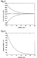
- FIGS. 3 and 4 shows the relationship between the air gap 20 and the Amplitude signal of the transducer 13, in non-linear, almost exponential form.
- FIG. 2 the Voltage of the output signal (sensor voltage) above the Air gap 20 plotted, while Figure 3, the output signal, DC voltage and sign adjusted, above the air gap is applied.
- the method according to the invention works as follows:
- the amplitude signal is then at each peak of the Half-wave or each time the magnetic areas N, S change or poles or marks of the encoder 17 to a nominal value normalized.
- This denomination comes with a shear force zero point or force offset that correlates almost simultaneously with a Force measuring element, preferably a Meßfelge, under the influence the forces occurring on the wheel 12 has been determined once.
- the lateral force value is in the stationary driving behavior ideally 0 N.
- the lateral forces can then essentially as a function of Distance changes are determined.
Description
Die Erfindung betrifft ein Verfahren und eine Regelschaltung zur Erfassung und Auswertung von fahrdynamischen Zuständen eines Kraftfahrzeugs mittels Radkraftsensoren, vorzugsweise mit Reifensensoren, die als Maß für die auf das Rad bzw. den Reifen wirkenden Querkräfte den voreingestellten Luftspalt zwischen mindestens einem rotierenden Encoder und mindestens einem Meßwertaufnehmer heranziehen.The invention relates to a method and a control circuit for recording and evaluating dynamic driving conditions a motor vehicle by means of Radkraftsensoren, preferably with Tire sensors, as a measure of the on the wheel or the tire acting lateral forces the preset air gap between at least one rotating encoder and at least one Use the transducer.
Es ist eine Vielzahl von Verfahren zur Regelung des Fahrverhaltens eines Fahrzeugs bekannt, die Reifensensoren zur Erfassung der an den Reifen angreifenden Kräfte und Momente verwenden. Unter einem Reifensensor (SWT-Sensor) wird hierbei der im oder am Reifen angebrachte Encoder und mindestens ein dem Encoder zugeordneter, stationär am Chassis angeordnete mindestens eine Meßwertaufnehmer verstanden. Während in der EP 04 441 09 B1 die Deformation des Reifenprofilbereichs des Reifens - der Reifenlatsch - überwacht wird, wird in der WO 96/10505 die Deformation der Seitenwand - die Torsionsdeformationen - eines Reifens über eine Zeitspannenmessung zwischen dem Passieren mindestens zweier auf unterschiedlichem Radius zur Rotationsachse angeordneter Marken am rotierenden Rad erfaßt. Ein Reifensensor , der bei einer Verformung des Reifens infolge der an dem Reifen angreifenden Kräfte eine Änderung der Phasenlage und/oder der Amplitude zwischen von Meßwertaufnehmern abgegebenen Ausgangssignalen erfaßt, ist in der WO 97/44673 beschrieben. Die Größe des Luftspalts zwischen dem Encoder bzw. den in der Reifenseitenwand eingelagerten magnetischen Arealen und den z.B. aktiven, magnetoresisten Meßwertaufnehmern bilden die Signale, die für die Zuordnung der auf den Reifen wirkenden Seiten- oder Querkräfte verwendet werden. Die Veränderungen der von dem Meßwertaufnehmer ermittelten Signale bilden folglich die Verformungen bzw. Veränderungen der Reifenseitenwand ab, die sich aufgrund der auf die Räder wirkenden Querkräfte einstellen, während die Änderung der Phasenlage zwischen den zwei auf einem äußeren und einem inneren Radius zur Rotationsachse des Rads angeordneten Meßwertaufnehmern ein Signal für die Berechnung der Längskräfte definieren.There are a variety of methods of regulating the Driving behavior of a vehicle known to the tire sensors Detecting the forces and moments acting on the tire use. Under a tire sensor (SWT sensor) is hereby the encoder mounted in or on the tire and at least one associated with the encoder, stationarily arranged on the chassis understood at least one transducer. While in the EP 04 441 09 B1 the deformation of the tire tread portion of the Tire - the tire gossip - is monitored in the WO 96/10505 the deformation of the sidewall - the Torsion deformations - of a tire over one Time span measurement between passing at least two different radius to the axis of rotation arranged brands detected on the rotating wheel. A tire sensor at a Deformation of the tire due to the attacking on the tire Forces a change in the phase angle and / or the amplitude between output from transducers output signals is described in WO 97/44673. The size of the Air gap between the encoder or in the Tire sidewall embedded magnetic areas and the e.g. active, magnetoresistive transducers form the Signals that are responsible for the assignment of the tire Lateral or transverse forces are used. The changes of detected by the transducer signals thus form the deformations or changes of the tire sidewall, due to the lateral forces acting on the wheels while changing the phase angle between the two on an outer and inner radius to Rotary axis of the wheel arranged transducers Defining the signal for the calculation of the longitudinal forces.
Ein weiterer, mit einem magnetischen Encoder ausgerüsteter Luftreifen, ist in der DE 196 20 582 A1 beschrieben, auf die vollumfänglich verwiesen wird. Die an einem Rad mit einem derartigen Reifen angreifenden Kräfte, die mit den Meßwertaufnehmern oder Signalaufbereitungseinrichtungen in Form von mit Kräften korrelierten Signalen abgebildet werden, dienen in Kraftfahrzeug-Regelungssystemen zur Regelung bzw. Steuerung von Fahrzeugen, insbesondere zur Bemessung und/oder Modulation des Bremsdruckes in den Radbremsen der Räder.Another, equipped with a magnetic encoder Pneumatic tire is described in DE 196 20 582 A1, to the is fully referenced. The one on a bike with one such tire attacking forces, with the Transducers or signal conditioning devices in Form of signals correlated with forces, serve in motor vehicle control systems for regulation or Control of vehicles, in particular for design and / or Modulation of the brake pressure in the wheel brakes of the wheels.
Bei der Ermittlung des funktionalen Zusammenhanges des
Amplituden- und/oder Phasensignales zu den auf die Räder bzw.
die Reifen wirkenden Kräfte werden Meßfelgen verwendet, wie sie
Beispielshaft in der EP 0 352 788 A2 beschrieben sind. Dabei
ist es nötig, die Meßwertaufnehmer duplizierbar an dem Chassis
bzw. der Radaufhängung anzuordnen, um die vom Luftspalt
abhängigen Signale reproduzierbar zu gestalten. Sich bei der
Anordnung oder Fertigung der Meßwertaufnehmer ergebende
Toleranzen und/oder unterschiedliche Felgensysteme, z.B. mit
unterschiedlichen Einpreßtiefen, führen zu Abweichungen bei der
Bestimmung der auf die Räder bzw. Reifen wirkenden Kräfte.In determining the functional relationship of the
Amplitude and / or phase signals to the on the wheels or
the tire-acting forces are used measuring rims, as they
Examples are described in
Der Erfindung liegt die Aufgabe zugrunde, eine fehlerreduzierte Auswertung von Radkräften, insbesondere von mittels Reifensensoren erfassten Verformungen der Felge und/oder des Reifens, zu ermöglichen. The invention is based on the object, a reduced-error Evaluation of wheel forces, in particular by means of Tire sensors detected deformations of the rim and / or the Tire, allow.
Diese Aufgabe wird erfindungsgemäß durch die Merkmale der unabhängigen Ansprüche gelöst. Abhängige Ansprüche sind auf bevorzugte Ausführungsformen gerichtet.This object is achieved by the features of solved independent claims. Dependent claims are up directed preferred embodiments.
Vorteilhaft kann zur Erfassung und Auswertung von fahrdynamischen Zuständen eines Kraftfahrzeugs mittels Radkraftsensoren, vorzugsweise mit Reifensensoren, als Maß für die auf das Rad bzw. den Reifen wirkenden Querkräfte der voreingestellte Luftspalt zwischen mindestens einem rotierenden Encoder und mindestens einem Meßwertaufnehmer herangezogen werden. Dadurch, daß erfindungsgemäß der von dem Luftspalt abhängige Betriebspunkt des Ausgangssignals des Meßwertaufnehmers oder einer z.B. dem Meßwertaufnehmer nachgeschalteten Signalaufbereitungseinrichtung unabhängig von dessen Voreinstellung eingestellt wird, läßt sich ohne Verlust an Signalqualität das Ausgangssignal fehlerreduziert verarbeiten, da es unabhängig von diesem voreingestellten Abstand zwischen Meßwertaufnehmer und Encoder ermittelt wird. Es lassen sich Felgen mit unterschiedlicher Einpreßtiefe, jedoch mit gleicher Steifigkeit, verwenden. Hinzu kommt, daß der Abstand des Meßwertaufnehmers beliebig über den Auflösungsbereich variiert werden kann, ohne daß Anpassungen der funktionalen Abbildung zwischen der Amplitude und der Querkraft erforderlich sind.Advantageously, for the detection and evaluation of vehicle dynamic states of a motor vehicle by means of Radkraftsensoren, preferably with tire sensors, as a measure of the lateral forces acting on the wheel or the tire Preset air gap between at least one rotating Encoder and at least one transducer used become. Characterized in that the invention of the air gap dependent operating point of the output signal of the Transducer or a e.g. the transducer downstream signal conditioning device independent of whose default setting is set, can be without loss at signal quality, the output signal error-reduced process as it is independent of this preset Distance between transducer and encoder is determined. It can be rims with different Einpreßtiefe, but with equal rigidity, use. In addition, that the distance of the transducer as desired over the Resolution range can be varied without any adjustments the functional mapping between the amplitude and the Shear force are required.
Vorteilhaft ist eine gattungsgemäße Regelschaltung so augestaltet, daß zur Erfassung und Auswertung von fahrdynamischen Zuständen eines Kraftfahrzeugs mittels Radkraftsensoren, vorzugsweise mit Reifensensoren, die als Maß für die auf das Rad bzw. den Reifen wirkenden Querkräfte den voreingestellten Luftspalt zwischen mindestens einem rotierenden Encoder und mindestens einem Meßwertaufnehmer heranziehen, sie eine Ermittlungseinheit enthält, die den von dem Luftspalt abhängigen Betriebspunkt des Ausgangssignals des Meßwertaufnehmers oder einer Signalaufbereitungseinrichtung unabhängig von dessen Voreinstellung einstellt.Advantageous is a generic control circuit so stated that for the detection and evaluation of vehicle dynamic states of a motor vehicle by means of Radkraftsensoren, preferably with tire sensors, as a measure for acting on the wheel or the tire lateral forces the Preset air gap between at least one rotating encoder and at least one transducer it contains an investigative unit corresponding to that of the air gap dependent operating point of the output signal of the Measuring transducer or a signal conditioning device regardless of its default setting.
Die Erfindung sieht vor, das Verfahren und die Regeschaltung so
auszugestalten, daß eine Adaption des Ausgangssignals an die
fahrzeugspezifischen Abstände zwischen dem Meßwertaufnehmer und
dem Encoder erfolgt. Ein zweckmäßiges Verfahren und eine
Regelschaltung zeichnen sich dadurch aus, daß das
Ausgangssignal bei stationärem, längs- bzw. querkraftfreiem
Fahrverhalten auf mindestens einen Nennwert normiert wird. Das
stationäre, längs- bzw. querkraftfreie Fahrverhalten wird mit
Hilfe von Eingangsgrößen festgestellt, die von herkömmlichen
Sensoren bereitgestellt werden und die mindestens die
Querbeschleunigung, die Längsbeschleunigung und die
Lenkwinkelgeschwindigkeit umfassen. Geeigneterweise wirken zu
diesem Zeitpunkt kleine oder nahezu keine Längs- bzw.
Querkräfte auf das Rad bzw. den Reifen. Dabei können folgende
Bedingungen einzeln oder in beliebiger Kombination einem
stationären, längs- und querkraftfreien Fahrverhalten zugrunde
gelegt sein:
Wenn vorzugsweise alle diese Bedingungen über einen Zeitraum von ca.70 ms stabil sind, wird derjenige Wert (Nennwert) festgelegt, auf den das Ausgangssignal bezogen (normiert) werden kann.If preferably all of these conditions over a period of time of about 70 ms, the value (nominal value) to which the output signal relates (normalized) can be.
Das von dem Meßwertaufnehmer oder einer Signalaufbereitung zur Verfügung gestellte Ausgangssignal ist ein sinusförmiges Wechselspannungs- oder -stromsignal, dessen Nennwert bei jedem Spitzenwert der Halbwelle (Amplitude) bzw. bei jedem Wechsel der Pole oder Marken des Encoders bestimmt wird, wenn die Bedingungen des stationären Fahrverhaltens erfüllt sind. Dem Nennwert wird ein Wert zugeordnet, der den Nullpunkt(Offset) der auf das Rad und/oder den Reifen wirkenden Querkraft wiedergibt.That of the transducer or a signal conditioning for Provided output signal is a sinusoidal AC voltage or current signal, whose nominal value at each Peak value of the half-wave (amplitude) or at each change the pole or marks of the encoder is determined when the Conditions of stationary driving are met. the Denomination is assigned a value that is the zero point (offset) the lateral force acting on the wheel and / or the tire reproduces.
Die Bestimmung der Querkräfte erfolgt dann während dynamischer
Zustände des Fahrzeugs in Abhängigkeit von den
Amplitudenänderungen nach der Beziehung

Die Querkräfte können dann im Wesentlichen als Funktion der Abstandsänderungen ermittelt werden.The lateral forces can then essentially as a function of Distance changes are determined.
Ein Ausführungsbeispiel der Erfindung ist in der Zeichnung dargestellt und wird im folgenden näher beschrieben.An embodiment of the invention is in the drawing and will be described in more detail below.
Es zeigen
- Figur 1a,b
- eine Regelschaltung zur Erfassung und Auswertung der Verformungen des Rades unter Quer- bzw. Seitenkräften
- Figur 2
- eine Kennline des Meßwertaufnehmers eines Reifensensors
- Figur 3
- die Kennlinie gemäß Figur 2, Gleichspannungs- und Vorzeichen bereinigt
- FIG. 1a, b
- a control circuit for detecting and evaluating the deformations of the wheel under lateral or lateral forces
- FIG. 2
- a characteristic of the transducer of a tire sensor
- FIG. 3
- the characteristic curve according to FIG. 2, DC voltage and sign corrected
Figur 1 a und b zeigen eine Regelschaltung 10, die mit zwei in
radialem Abstand von der Rotationsachse 11 des Rades
12 am Chassis eines Kraftfahrzeugs angeordneten
magnetfeldempfindlichen Meßwertaufnehmern 13, 14
verbunden ist. Die Regelschaltung kann Bestandteil
der Meßwertaufnehmer oder eine separate Einheit bzw.
Bestandteil von ABS (Antiblockierregelsystem), von ASR
(Antriebsschlupfregelung), von ESP (Elektronisches
Fahrstabilitätsregelungssystem), von EHB (Elektrohydraulisches
Bremsregelungssystem), eines Fahrwerksregelungssystems und/oder
eines EMB (Elektomechanisches Brems-)-Regelungssystems sein.
Der Fahrzeugreifen 15 weist einen Encoder 17 mit
permanentmagnetischen Arealen mit wechselnder Polarität N, S
auf. Die permanentmagnetischen Areale N, S sind in der
Reifenwandung 18 des Rades 12 eingelagert. Zwischen dem Encoder
17 und den Meßwertaufnehmern 13, 14 ist ein Abstand
voreingestellt(ein Luftspalt 20). Die Meßwertaufnehmer 13, 14
erfassen bei einer Verformung des Rades ( = Felge 16 mit dem
Reifen 15) infolge der am Reifen angreifenden Längskräfte eine
Änderung der Phasenlage 18 die zwischen den von den
Meßwertaufnehmern 13, 14 abgegebenen Meßsignalen auftritt.
Weiterhin erfasst mindestens der eine Meßwertaufnehmer 13 bei
einer Verformung des Rades 12 infolge der am Reifen 15
angreifenden Querkräfte eine Änderung der Amplitude 19 des
Meßsignales. Das Meßsignal wird durch einen sensorintegrierten
elektronischen Schaltkreis verstärkt und in ein Ausgangssignal
gewandelt. In einer Ermittlungseinheit 21 wird der von dem
Luftspalt 20 abhängige Betriebspunkt des Ausgangssignals des
Meßwertaufnehmers 13 unabhängig von der Voreinstellung
einstellt. Hierzu wird das Ausgangssignal bei stationärem
Fahrverhalten des Fahrzeugs auf einen Nennwert normiert und
über Mittel 21 der Nennwert mit dem Querkraft-Nullpunkt
korreliert. Danach besteht ein reproduzierbarer Zusammenhang
zwischen der Veränderung des Amplitudensignals und der
Veränderung der Querkraft.Figure 1 a and b show a
Das sinusförmige Ausgangssignal, das durch die Wirkung des
Encoders 17 am magnetfeldempfindlichen Meßwertaufnehmer 13
entsteht und dessen Spitzenwert mit dem Luftspalt 20 variiert,
kann ein Wechselspannungssignal oder ein Wechselstromsignal
sein. Das Wechselstromsignal kann in einer dem Meßwertaufnehmer
13 zugeordneten Signalaufbereitungseinrichtung in ein
Wechselspannungssignal transformiert werden. Figur 3 und 4
zeigt den Zusammenhang zwischen dem Luftspalt 20 und dem
Amplitudensignal des Meßwertaufnehmers 13, und zwar in nichtlinearer,
nahezu exponentieller Form. In Figur 2 ist die
Spannung des Ausgangssignals (Sensor-Spannung) über dem
Luftspalt 20 aufgetragen, während Figur 3 das Ausgangssignal,
Gleichspannungs- und Vorzeichen bereinigt, über dem Luftspalt
aufgetragen ist.The sinusoidal output signal caused by the effect of
Das Verfahren nach der Erfindung arbeitet wie folgt:The method according to the invention works as follows:
Nach dem Start des Kraftfahrzeugs wird das Fahrverhalten mit
Signalen von konventionellen Sensoren, wie Querbeschleunigungsund
Längsbeschleunigungssensoren, Gierratensensoren,
Lenkwinkelsensoren u.dgl., ermittelt, da die Adaptation des
Amplitudensignals an den Luftspalt 20 nur bei stationären
Bedingungen erfolgen soll. Um ein stationäres, längs- bzw.
querkraftfreies Fahrverhalten festzustellen, sollen
vorzugsweise folgende Bedingungen erfüllt sein:
Wenn diese Bedingungen erfüllt und ca. 70 ms stabil sind, liegt
ein stationäres, längs- bzw. querkraftfreies Fahrverhalten vor.
Das Amplitudensignal wird dann bei jedem Spitzenwert der
Halbwelle bzw. bei jedem Wechsel der magnetischen Areale N, S
bzw. Pole oder Marken des Encoders 17 auf einen Nennwert
normiert. Dieser Nennwert wird mit einem Querkraft-Nullpunkt
bzw. Kraft-Offset korreliert, der nahezu zeitgleich mit einem
Kraftmeßelement, vorzugsweise einer Meßfelge, unter dem Einfluß
der an dem Rad 12 auftretenden Kräfte einmal bestimmt wurde.
Der Querkraftwert ist bei dem stationären Fahrverhalten
idealerweise 0 N.If these conditions are met and about 70 ms are stable, lies
a stationary, longitudinal or transverse force-free driving behavior before.
The amplitude signal is then at each peak of the
Half-wave or each time the magnetic areas N, S change
or poles or marks of the
Ausgehend von dem mit dem Kraft-Offset korrelierten normierten
Nennwert des Amplitudensignals werden die Querkräfte bei
dynamischen Zuständen des Fahrzeugs in Abhängigkeit von den
Amplitudenänderungen AmpNutzwert nach der Beziehung

Die Querkräfte können dann im Wesentlichen als Funktion der Abstandsänderungen ermittelt werden.The lateral forces can then essentially as a function of Distance changes are determined.
Claims (13)
- Method for detecting and evaluating the conditions of vehicle movement dynamics of a motor vehicle by means of wheel force sensors, preferably tire sensors, which take the pre-adjusted air slot between at least one rotating encoder and at least one pick-up for measuring data into account as a standard for the transverse forces that act on the wheel or on the tire,
characterized in that the air-slot-dependent operating point of the output signal of the pick-up for measuring data or a signal-conditioning device is set irrespective of the pre-adjustment of the said point which was made during predetermined driving behaviour. - Method as claimed in claim 1,
characterized in that the output signal is standardized to at least one nominal value when the driving behaviour is stationary. - Method as claimed in claim 1 or 2,
characterized in that the output signal is a sinusoidal alternating voltage signal or alternating current signal, and the nominal value is determined with each peak value of the half wave (amplitude) or with each alternation of the poles or markings of the encoder. - Method as claimed in any one of claims 1 to 3,
characterized in that associated with the nominal value is a value which represents the zero point (offset) of the transverse force acting on the wheel and/or the tire. - Method as claimed in any one of claims 1 to 4,
characterized in that the transverse forces are determined in dependence on the amplitude variations according to the relation - Method as claimed in claim 5,
characterized in that the amplitude variations are attributed by means of an inverse function to changes in distance according to the relationwherein Disuseful effect = changes in distance and k = negative constant.
- Method as claimed in claim 6,
characterized in that the transverse forces are basically determined as a function of the changes in distance. - Method as claimed in any one of claims 1 to 7,
characterized in that the nominal value is maintained until the predetermined driving behaviour is detected. - Control circuit for detecting and evaluating the conditions of vehicle movement dynamics of a motor vehicle by means of wheel force sensors, preferably tire sensors, which take the pre-adjusted air slot between at least one rotating encoder and at least one pick-up for measuring data into account as a standard for the transverse forces that act on the wheel or on the tire,
characterized by a determination unit which sets the air-slot-dependent operating point of the output signal of the pick-up for measuring data or a signal-conditioning device irrespective of the said point's pre-adjustment which was made during predetermined driving behaviour. - Control circuit as claimed in claim 9,
characterized by a standardization of the output signal to at least one nominal value when the vehicle movement behaviour is stationary. - Control circuit as claimed in claim 9 or 10,
characterized in that the output signal of the pick-up for measuring data or the signal-evaluating device is a sinusoidal alternating voltage signal or alternating current signal, and the determination unit determines the nominal value with each peak value of the half wave (amplitude) or with each alternation of the poles or markings of the encoder. - Control circuit as claimed in any one of claims 9 to 11,
characterized in that there is provision of means attributing a value to the nominal value which represents the zero point (offset) of the transverse force, and in that the determination unit determines the transverse forces in dependence on the amplitude variations according to the relation - Control circuit as claimed in claim 12,
characterized in that the determination unit attributes the amplitude variations by means of an inverse function to changes in distance according to the relationwherein Disuseful effect = changes in distance and k = negative constant.
Applications Claiming Priority (7)
| Application Number | Priority Date | Filing Date | Title |
|---|---|---|---|
| DE19944098 | 1999-09-15 | ||
| DE19944098 | 1999-09-15 | ||
| DE10026111 | 2000-05-26 | ||
| DE10026111 | 2000-05-26 | ||
| DE10044291A DE10044291A1 (en) | 1999-09-15 | 2000-09-07 | Method for recording and evaluating driving dynamics states of a motor vehicle |
| DE10044291 | 2000-09-07 | ||
| PCT/EP2000/008989 WO2001019654A1 (en) | 1999-09-15 | 2000-09-14 | Method for detecting and evaluating the conditions of vehicle movement dynamics for a motor vehicle |
Publications (2)
| Publication Number | Publication Date |
|---|---|
| EP1216175A1 EP1216175A1 (en) | 2002-06-26 |
| EP1216175B1 true EP1216175B1 (en) | 2005-06-01 |
Family
ID=27213883
Family Applications (1)
| Application Number | Title | Priority Date | Filing Date |
|---|---|---|---|
| EP00964171A Expired - Lifetime EP1216175B1 (en) | 1999-09-15 | 2000-09-14 | Method for detecting and evaluating the conditions of vehicle movement dynamics for a motor vehicle |
Country Status (4)
| Country | Link |
|---|---|
| US (1) | US6988395B1 (en) |
| EP (1) | EP1216175B1 (en) |
| JP (1) | JP2003509665A (en) |
| WO (1) | WO2001019654A1 (en) |
Families Citing this family (6)
| Publication number | Priority date | Publication date | Assignee | Title |
|---|---|---|---|---|
| JP2005524054A (en) * | 2001-10-05 | 2005-08-11 | コンティネンタル・テーベス・アクチエンゲゼルシヤフト・ウント・コンパニー・オッフェネ・ハンデルスゲゼルシヤフト | Combination detection device and pressure determination method of axle acceleration and wheel rotation speed |
| JP4520783B2 (en) * | 2004-07-14 | 2010-08-11 | 住友ゴム工業株式会社 | Detection method of longitudinal force acting on tire |
| FR2877088B1 (en) * | 2004-10-25 | 2007-01-12 | Michelin Soc Tech | METHOD OF DECOINING A PNEUMATIC |
| FR2900893B1 (en) * | 2006-05-10 | 2008-06-20 | Bosch Gmbh Robert | METHOD FOR ADJUSTING A DYNAMIC TRACK CONTROL SYSTEM FOR A MOTOR VEHICLE. |
| FR2908509B1 (en) * | 2006-11-15 | 2009-02-20 | Michelin Soc Tech | METHOD FOR DATASING AN OUTSTANDING ANGULAR POSITION OF A SENSOR CARRIED BY A TIRE |
| JP5395618B2 (en) * | 2009-10-29 | 2014-01-22 | 住友ゴム工業株式会社 | Method for estimating force acting on tire, and assembly of tire and tire wheel used therefor |
Family Cites Families (22)
| Publication number | Priority date | Publication date | Assignee | Title |
|---|---|---|---|---|
| JPS6161405U (en) * | 1984-09-28 | 1986-04-25 | ||
| DE3812904A1 (en) | 1988-03-09 | 1989-09-21 | Lucas Ind Plc | BLOCK-PROTECTED BRAKE SYSTEM WITH MONITORED SPEED SENSOR AND METHOD FOR MEASURING THE SPEED IN SUCH A BRAKE SYSTEM |
| JPH04213036A (en) * | 1990-09-20 | 1992-08-04 | Honda Motor Co Ltd | Apparatus for correcting midpoint of steering force sensor |
| US5408411A (en) * | 1991-01-18 | 1995-04-18 | Hitachi, Ltd. | System for predicting behavior of automotive vehicle and for controlling vehicular behavior based thereon |
| JPH0682206A (en) * | 1992-08-31 | 1994-03-22 | Nhk Spring Co Ltd | Non-contact position detector |
| DE4305155C2 (en) * | 1993-02-19 | 2002-05-23 | Bosch Gmbh Robert | Device for regulating the driving dynamics |
| US5402344A (en) * | 1993-08-23 | 1995-03-28 | Martin Marietta Energy Systems, Inc. | Method for controlling a vehicle with two or more independently steered wheels |
| DE4435160A1 (en) | 1994-09-30 | 1996-04-04 | Continental Ag | Device for determining the peripheral force of a vehicle wheel |
| DE19649137B4 (en) | 1995-12-08 | 2006-08-31 | Volkswagen Ag | Method for controlling the dynamic behavior of a motor vehicle |
| US6336364B1 (en) * | 1996-01-31 | 2002-01-08 | Hunter Engineering Company | Wheel balancer with wheel rim runout measurement |
| DE19607050A1 (en) | 1996-02-03 | 1997-08-07 | Teves Gmbh Alfred | Method for determining variables that describe the driving behavior of a vehicle |
| JP3470502B2 (en) * | 1996-05-30 | 2003-11-25 | 日産自動車株式会社 | Throttle sensor detection value processing device |
| DE19623595A1 (en) * | 1996-06-13 | 1997-12-18 | Teves Gmbh Alfred | Method for regulating the driving behavior of a vehicle |
| JP3360528B2 (en) * | 1996-06-19 | 2002-12-24 | 日産自動車株式会社 | Vehicle motion control device |
| DE19624795A1 (en) * | 1996-06-21 | 1998-01-02 | Teves Gmbh Alfred | Method for regulating the driving behavior of a vehicle with tire sensors |
| JPH10153131A (en) * | 1996-11-22 | 1998-06-09 | Aisan Ind Co Ltd | Throttle valve opening detector |
| JP3391646B2 (en) * | 1997-02-13 | 2003-03-31 | オークマ株式会社 | Position detection device with error correction function |
| DE19744725A1 (en) | 1997-10-10 | 1999-04-15 | Itt Mfg Enterprises Inc | Method to determine variable characteristics, which define motor vehicle behavior |
| JP3850530B2 (en) * | 1997-10-21 | 2006-11-29 | 富士重工業株式会社 | Vehicle motion control device |
| JP3810540B2 (en) * | 1997-12-15 | 2006-08-16 | 株式会社トプコン | Surveyor with adjustment function of rotary encoder |
| EP1089901B1 (en) * | 1998-06-22 | 2002-01-09 | Continental Teves AG & Co. oHG | Regulating circuit for regulating the driving stability of a motor vehicle using a motor vehicle reference model |
| WO2000003901A1 (en) | 1998-07-16 | 2000-01-27 | Continental Teves Ag & Co. Ohg | Method and device for detecting the critical driving states in vehicles which are being driven |
-
2000
- 2000-09-14 WO PCT/EP2000/008989 patent/WO2001019654A1/en active IP Right Grant
- 2000-09-14 JP JP2001523256A patent/JP2003509665A/en active Pending
- 2000-09-14 US US10/088,193 patent/US6988395B1/en not_active Expired - Fee Related
- 2000-09-14 EP EP00964171A patent/EP1216175B1/en not_active Expired - Lifetime
Also Published As
| Publication number | Publication date |
|---|---|
| EP1216175A1 (en) | 2002-06-26 |
| JP2003509665A (en) | 2003-03-11 |
| US6988395B1 (en) | 2006-01-24 |
| WO2001019654A1 (en) | 2001-03-22 |
Similar Documents
| Publication | Publication Date | Title |
|---|---|---|
| DE102012217901B3 (en) | Method, controller and system for determining a tread depth of a tread of a tire | |
| EP2170631B1 (en) | Method and device for monitoring the state of tyres | |
| EP1387787B1 (en) | Method and system for controlling the performance of a motor vehicle | |
| DE102007047399B4 (en) | Method for detecting a loading state of a motor vehicle | |
| DE19735562B4 (en) | Method and device for determining the reference speed in a motor vehicle | |
| EP0938987A2 (en) | Method and apparatus for monitoring the tyre pressure of motor vehicle wheels | |
| EP3600920A1 (en) | Method, control device, and system for determining a profile depth of a profile of a tyre | |
| EP1347903A1 (en) | System and method for determining the load state of a motor vehicle | |
| DE10329700B4 (en) | Method and device for determining the tire inflation pressure and the wheel load of a vehicle tire | |
| EP1732772A1 (en) | Tire sensitivity recognition method | |
| EP3027436B1 (en) | Method and system for determining a pressure ratio between a target tire pressure and a current tire pressure for a tire of a vehicle | |
| EP1216175B1 (en) | Method for detecting and evaluating the conditions of vehicle movement dynamics for a motor vehicle | |
| DE10160046B4 (en) | System and method for monitoring the traction of a motor vehicle | |
| WO2000046088A1 (en) | Servo-system for a motor vehicle, said servo-system comprising a tyre sensor | |
| DE10304126A1 (en) | Measurement of tire pressure, tire pressure loss and tire profile by comparison of ABS derived velocity and distance traveled with reference velocity and distance traveled measurements | |
| DE19537791C2 (en) | Method and device for determining the driving speed of a motor vehicle | |
| DE102007021918A1 (en) | Method for monitoring the tire condition in vehicles | |
| DE10044291A1 (en) | Method for recording and evaluating driving dynamics states of a motor vehicle | |
| EP1092967B1 (en) | Procedure and device for testing the braking arrangement of a vehicle | |
| WO2002053428A1 (en) | System and method for monitoring the cornering dynamics of a motor vehicle | |
| EP1167143A2 (en) | Method and device for emergency braking detection | |
| DE102007058998A1 (en) | Indirect tire pressure monitoring method for e.g. motor cycle, involves implementing recognition of tire pressure loss, and determining testing variable exclusive of rotating speed of front wheel and/or rotating speed of rear wheel | |
| DE10122405B4 (en) | Apparatus and method for monitoring the driving condition of a vehicle | |
| WO2001032483A1 (en) | Method and system for detection of wheel oscillations | |
| DE102011121496A1 (en) | Electronic device for vehicle system for controlling or regulation of a vehicle and for determining parameters, particularly wheel dimensions in vehicle, has wheel speed detection unit for determining wheel speed of vehicle wheel |
Legal Events
| Date | Code | Title | Description |
|---|---|---|---|
| PUAI | Public reference made under article 153(3) epc to a published international application that has entered the european phase |
Free format text: ORIGINAL CODE: 0009012 |
|
| 17P | Request for examination filed |
Effective date: 20020415 |
|
| AK | Designated contracting states |
Kind code of ref document: A1 Designated state(s): AT BE CH CY DE DK ES FI FR GB GR IE IT LI LU MC NL PT SE |
|
| RBV | Designated contracting states (corrected) |
Designated state(s): DE FR GB |
|
| GRAP | Despatch of communication of intention to grant a patent |
Free format text: ORIGINAL CODE: EPIDOSNIGR1 |
|
| GRAA | (expected) grant |
Free format text: ORIGINAL CODE: 0009210 |
|
| GRAS | Grant fee paid |
Free format text: ORIGINAL CODE: EPIDOSNIGR3 |
|
| AK | Designated contracting states |
Kind code of ref document: B1 Designated state(s): DE FR GB |
|
| REG | Reference to a national code |
Ref country code: GB Ref legal event code: FG4D Free format text: NOT ENGLISH |
|
| REF | Corresponds to: |
Ref document number: 50010472 Country of ref document: DE Date of ref document: 20050707 Kind code of ref document: P |
|
| GBT | Gb: translation of ep patent filed (gb section 77(6)(a)/1977) |
Effective date: 20050801 |
|
| ET | Fr: translation filed | ||
| PLBE | No opposition filed within time limit |
Free format text: ORIGINAL CODE: 0009261 |
|
| STAA | Information on the status of an ep patent application or granted ep patent |
Free format text: STATUS: NO OPPOSITION FILED WITHIN TIME LIMIT |
|
| 26N | No opposition filed |
Effective date: 20060302 |
|
| PGFP | Annual fee paid to national office [announced via postgrant information from national office to epo] |
Ref country code: GB Payment date: 20110920 Year of fee payment: 12 Ref country code: DE Payment date: 20110930 Year of fee payment: 12 Ref country code: FR Payment date: 20110927 Year of fee payment: 12 |
|
| REG | Reference to a national code |
Ref country code: DE Ref legal event code: R231 Ref document number: 50010472 Country of ref document: DE |
|
| PG25 | Lapsed in a contracting state [announced via postgrant information from national office to epo] |
Ref country code: DE Free format text: LAPSE BECAUSE OF THE APPLICANT RENOUNCES Effective date: 20120217 |
|
| GBPC | Gb: european patent ceased through non-payment of renewal fee |
Effective date: 20120914 |
|
| REG | Reference to a national code |
Ref country code: FR Ref legal event code: ST Effective date: 20130531 |
|
| PG25 | Lapsed in a contracting state [announced via postgrant information from national office to epo] |
Ref country code: GB Free format text: LAPSE BECAUSE OF NON-PAYMENT OF DUE FEES Effective date: 20120914 |
|
| PG25 | Lapsed in a contracting state [announced via postgrant information from national office to epo] |
Ref country code: FR Free format text: LAPSE BECAUSE OF NON-PAYMENT OF DUE FEES Effective date: 20121001 |