EP1167143A2 - Method and device for emergency braking detection - Google Patents
Method and device for emergency braking detection Download PDFInfo
- Publication number
- EP1167143A2 EP1167143A2 EP01113777A EP01113777A EP1167143A2 EP 1167143 A2 EP1167143 A2 EP 1167143A2 EP 01113777 A EP01113777 A EP 01113777A EP 01113777 A EP01113777 A EP 01113777A EP 1167143 A2 EP1167143 A2 EP 1167143A2
- Authority
- EP
- European Patent Office
- Prior art keywords
- speed
- wheels
- value
- determined
- detected
- Prior art date
- Legal status (The legal status is an assumption and is not a legal conclusion. Google has not performed a legal analysis and makes no representation as to the accuracy of the status listed.)
- Granted
Links
- 238000001514 detection method Methods 0.000 title claims description 14
- 238000000034 method Methods 0.000 title claims description 13
- 230000008859 change Effects 0.000 claims description 22
- 238000012935 Averaging Methods 0.000 claims description 3
- 230000004044 response Effects 0.000 claims description 3
- 230000001133 acceleration Effects 0.000 description 8
- 238000011156 evaluation Methods 0.000 description 3
- 230000008901 benefit Effects 0.000 description 2
- 238000006243 chemical reaction Methods 0.000 description 2
- 230000000694 effects Effects 0.000 description 2
- 230000008569 process Effects 0.000 description 2
- 230000000903 blocking effect Effects 0.000 description 1
- 238000010586 diagram Methods 0.000 description 1
- 238000006073 displacement reaction Methods 0.000 description 1
- 230000009467 reduction Effects 0.000 description 1
- 230000002123 temporal effect Effects 0.000 description 1
- 230000007704 transition Effects 0.000 description 1
Images


Classifications
-
- B—PERFORMING OPERATIONS; TRANSPORTING
- B60—VEHICLES IN GENERAL
- B60T—VEHICLE BRAKE CONTROL SYSTEMS OR PARTS THEREOF; BRAKE CONTROL SYSTEMS OR PARTS THEREOF, IN GENERAL; ARRANGEMENT OF BRAKING ELEMENTS ON VEHICLES IN GENERAL; PORTABLE DEVICES FOR PREVENTING UNWANTED MOVEMENT OF VEHICLES; VEHICLE MODIFICATIONS TO FACILITATE COOLING OF BRAKES
- B60T8/00—Arrangements for adjusting wheel-braking force to meet varying vehicular or ground-surface conditions, e.g. limiting or varying distribution of braking force
- B60T8/32—Arrangements for adjusting wheel-braking force to meet varying vehicular or ground-surface conditions, e.g. limiting or varying distribution of braking force responsive to a speed condition, e.g. acceleration or deceleration
- B60T8/321—Arrangements for adjusting wheel-braking force to meet varying vehicular or ground-surface conditions, e.g. limiting or varying distribution of braking force responsive to a speed condition, e.g. acceleration or deceleration deceleration
- B60T8/3255—Systems in which the braking action is dependent on brake pedal data
- B60T8/3275—Systems with a braking assistant function, i.e. automatic full braking initiation in dependence of brake pedal velocity
-
- B—PERFORMING OPERATIONS; TRANSPORTING
- B60—VEHICLES IN GENERAL
- B60T—VEHICLE BRAKE CONTROL SYSTEMS OR PARTS THEREOF; BRAKE CONTROL SYSTEMS OR PARTS THEREOF, IN GENERAL; ARRANGEMENT OF BRAKING ELEMENTS ON VEHICLES IN GENERAL; PORTABLE DEVICES FOR PREVENTING UNWANTED MOVEMENT OF VEHICLES; VEHICLE MODIFICATIONS TO FACILITATE COOLING OF BRAKES
- B60T7/00—Brake-action initiating means
- B60T7/12—Brake-action initiating means for automatic initiation; for initiation not subject to will of driver or passenger
-
- B—PERFORMING OPERATIONS; TRANSPORTING
- B60—VEHICLES IN GENERAL
- B60T—VEHICLE BRAKE CONTROL SYSTEMS OR PARTS THEREOF; BRAKE CONTROL SYSTEMS OR PARTS THEREOF, IN GENERAL; ARRANGEMENT OF BRAKING ELEMENTS ON VEHICLES IN GENERAL; PORTABLE DEVICES FOR PREVENTING UNWANTED MOVEMENT OF VEHICLES; VEHICLE MODIFICATIONS TO FACILITATE COOLING OF BRAKES
- B60T8/00—Arrangements for adjusting wheel-braking force to meet varying vehicular or ground-surface conditions, e.g. limiting or varying distribution of braking force
- B60T8/32—Arrangements for adjusting wheel-braking force to meet varying vehicular or ground-surface conditions, e.g. limiting or varying distribution of braking force responsive to a speed condition, e.g. acceleration or deceleration
- B60T8/88—Arrangements for adjusting wheel-braking force to meet varying vehicular or ground-surface conditions, e.g. limiting or varying distribution of braking force responsive to a speed condition, e.g. acceleration or deceleration with failure responsive means, i.e. means for detecting and indicating faulty operation of the speed responsive control means
- B60T8/885—Arrangements for adjusting wheel-braking force to meet varying vehicular or ground-surface conditions, e.g. limiting or varying distribution of braking force responsive to a speed condition, e.g. acceleration or deceleration with failure responsive means, i.e. means for detecting and indicating faulty operation of the speed responsive control means using electrical circuitry
-
- B—PERFORMING OPERATIONS; TRANSPORTING
- B60—VEHICLES IN GENERAL
- B60T—VEHICLE BRAKE CONTROL SYSTEMS OR PARTS THEREOF; BRAKE CONTROL SYSTEMS OR PARTS THEREOF, IN GENERAL; ARRANGEMENT OF BRAKING ELEMENTS ON VEHICLES IN GENERAL; PORTABLE DEVICES FOR PREVENTING UNWANTED MOVEMENT OF VEHICLES; VEHICLE MODIFICATIONS TO FACILITATE COOLING OF BRAKES
- B60T2201/00—Particular use of vehicle brake systems; Special systems using also the brakes; Special software modules within the brake system controller
- B60T2201/03—Brake assistants
-
- B—PERFORMING OPERATIONS; TRANSPORTING
- B60—VEHICLES IN GENERAL
- B60T—VEHICLE BRAKE CONTROL SYSTEMS OR PARTS THEREOF; BRAKE CONTROL SYSTEMS OR PARTS THEREOF, IN GENERAL; ARRANGEMENT OF BRAKING ELEMENTS ON VEHICLES IN GENERAL; PORTABLE DEVICES FOR PREVENTING UNWANTED MOVEMENT OF VEHICLES; VEHICLE MODIFICATIONS TO FACILITATE COOLING OF BRAKES
- B60T2270/00—Further aspects of brake control systems not otherwise provided for
- B60T2270/40—Failsafe aspects of brake control systems
- B60T2270/413—Plausibility monitoring, cross check, redundancy
-
- B—PERFORMING OPERATIONS; TRANSPORTING
- B60—VEHICLES IN GENERAL
- B60T—VEHICLE BRAKE CONTROL SYSTEMS OR PARTS THEREOF; BRAKE CONTROL SYSTEMS OR PARTS THEREOF, IN GENERAL; ARRANGEMENT OF BRAKING ELEMENTS ON VEHICLES IN GENERAL; PORTABLE DEVICES FOR PREVENTING UNWANTED MOVEMENT OF VEHICLES; VEHICLE MODIFICATIONS TO FACILITATE COOLING OF BRAKES
- B60T2270/00—Further aspects of brake control systems not otherwise provided for
- B60T2270/40—Failsafe aspects of brake control systems
- B60T2270/416—Wheel speed sensor failure
-
- Y—GENERAL TAGGING OF NEW TECHNOLOGICAL DEVELOPMENTS; GENERAL TAGGING OF CROSS-SECTIONAL TECHNOLOGIES SPANNING OVER SEVERAL SECTIONS OF THE IPC; TECHNICAL SUBJECTS COVERED BY FORMER USPC CROSS-REFERENCE ART COLLECTIONS [XRACs] AND DIGESTS
- Y10—TECHNICAL SUBJECTS COVERED BY FORMER USPC
- Y10S—TECHNICAL SUBJECTS COVERED BY FORMER USPC CROSS-REFERENCE ART COLLECTIONS [XRACs] AND DIGESTS
- Y10S188/00—Brakes
- Y10S188/01—Panic braking
Landscapes
- Engineering & Computer Science (AREA)
- Transportation (AREA)
- Mechanical Engineering (AREA)
- Regulating Braking Force (AREA)
Abstract
Description
Die Erfindung betrifft ein Verfahren und eine Vorrichtung zur Erkennung einer Panikbremsung mit den Merkmalen der unabhängigen Ansprüche.The invention relates to a method and a device to detect panic braking with the characteristics of the independent Expectations.
Unter einer Panikbremsung versteht man im Allgemeinen, dass der Fahrer des Fahrzeugs das Bremspedal schnell und stark betätigt. Aus dem Stand der Technik sind Systeme zur Erkennung einer Panikbremsung bekannt. So ist beispielsweise aus der DE 195 24 939 A eine Steuerung für eine Bremsanlage bekannt, bei der in bestimmten Betriebssituationen, die auf der Basis des Fahrerbremswunsches erkannt werden, Bremskraft über die eigentliche Fahrervorgabe hinaus auf die Radbremsen aufgebracht wird. Eine dieser Betriebssituationen ist eine Situation, in der aus der Reaktion des Fahrers auf eine Gefahrensituation geschlossen werden kann (Panikbremsung). Um diese Situation zu erkennen, wird die Art und Weise, wie der Fahrer das Bremsbetätigungselement betätigt, ausgewertet. Betätigt er das Element sehr schnell, was beispielsweise anhand der Änderung des Vordrucks der Bremsanlage erkannt wird, wird Druck über die Fahrervorgabe hinaus aufgebaut. Überschreitet die ausgewertete Größe einen vorgegebenen Schwellenwert (Auslöseschwelle), so findet der automatische Bremsvorgang, d.h. der erhöhte Bremskraftaufbau statt. Die Auslöseschwelle wird dabei auf der Basis vorgegebener Betriebsgrößen verändert, wobei die Auslöseschwelle erniedrigt wird, das heißt die Auslösung des erhöhten Bremskraftaufbaus empfindlicher gestaltet wird, wenn das Gefahrenpotential zunimmt. Als Betriebsgrößen sind dabei genannt der Vordruck der Bremsanlage, die Fahrzeuggeschwindigkeit, die Fahrzeugdrehrate, die Querbeschleunigung des Fahrzeugs, die Längsbeschleunigung des Fahrzeugs, die Lenkwinkeländerung, die abgegebene Motorleistung und/oder die Bremsdruckanforderung eines Fahrdynamikreglers.Panic braking is generally understood to mean that the driver of the vehicle applies the brake pedal quickly and strongly actuated. Systems for detection are from the prior art known a panic braking. For example, is out DE 195 24 939 A discloses a controller for a brake system, when in certain operating situations that are based on the basis of the driver's braking request are recognized, braking force beyond the actual driver specification on the wheel brakes is applied. One of these operating situations is one Situation in which from the driver's reaction to a dangerous situation can be closed (panic braking). Around Recognizing this situation becomes the way the Driver actuated the brake actuating element, evaluated. He actuates the element very quickly, for example based on the change in the form of the brake system detected pressure is built up beyond the driver's specification. If the evaluated size exceeds a given size Threshold (trigger threshold), so the automatic Braking, i.e. the increased braking force build up instead. The The trigger threshold is based on predetermined operating variables changed, the trigger threshold lowered is, that is the triggering of the increased braking force build-up is made more sensitive when the risk potential increases. The form is the company size the braking system, the vehicle speed, the vehicle rotation rate, the lateral acceleration of the vehicle, the Longitudinal acceleration of the vehicle, the change in steering angle, the engine power output and / or the brake pressure request of a vehicle dynamics controller.
Solche aus dem Stand der Technik bekannte Systeme benötigen zur Erkennung einer Panikbremsung eine relativ aufwendige und damit teuere Zusatzsensorik wie beispielsweise Bremspedalwegaufnehmer, Längsbeschleunigungssensoren oder Gierratensensoren.Such systems known from the prior art require To detect panic braking, a relatively complex one and therefore expensive additional sensors such as brake pedal displacement sensors, Longitudinal acceleration sensors or yaw rate sensors.
Erfindungsgemäß geschieht die Erkennung einer Panikbremsung bei einem Kraftfahrzeug mit wenigstens zwei Rädern dadurch, dass
- Drehzahlgrößen erfasst werden, die die Drehbewegungen wenigstens zweier Räder repräsentieren,
- die Drehzahlgröße eines der Räder ausgewählt wird und/oder aus den Drehzahlgrößen ein Drehzahlwert ermittelt wird,
- ein die zeitliche Änderung der ausgewählten Drehzahlgröße und/oder des Drehzahlwertes repräsentierender Änderungswert ermittelt wird,
- der zeitliche Verlauf des Änderungswertes ermittelt wird,
- abhängig von dem zeitlichen Verlauf des Änderungswertes eine Panikbremsung erkannt wird.
- Speed values are recorded which represent the rotary movements of at least two wheels,
- the speed variable of one of the wheels is selected and / or a speed value is determined from the speed variables,
- a change value representing the change over time of the selected speed variable and / or the speed value is determined,
- the time course of the change value is determined,
- depending on the time course of the change value, panic braking is detected.
Die Erfindung hat den Vorteil, dass zur Erkennung einer Panikbremsung keine aufwendige und teuere Zusatzsensorik notwendig ist; es genügen die ohnehin bei Antiblockierregelsystemen, Antriebsschlupfregelsystemen und/oder Fahrstabilitätssystemen vorgesehenen Raddrehzahlsensoren. Der Einsatz einer Panikerkennung ist damit auch in sogenannten Low-Cost-Bremsanlagen möglich.The invention has the advantage of being able to detect panic braking no complex and expensive additional sensors required is; they are sufficient with anti-lock control systems anyway, Anti-skid control systems and / or driving stability systems provided wheel speed sensors. The stake Panic detection is also used in so-called low-cost braking systems possible.
Durch die Erkennung einer Panikbremsung ist im Falle einer Panikbremsung eine Warnung des nachfolgenden Verkehrs möglich. Hier ist beispielsweise daran gedacht, in Reaktion auf eine erkannte Panikbremsung die Warnblinkanlage zu aktivieren.By detecting panic braking in the event of a Panic braking a warning of the following traffic possible. Here, for example, is thought in response to a detected panic braking to activate the hazard warning lights.
Weiterhin kann vorgesehen sein, dass das Erkennen einer Panikbremsung durch Abstandsregelsystemen (ACC-Systemen, Automatic Cruise Control) übermittelt werden, so dass nachfolgende Fahrzeuge ebenfalls stark abgebremst werden.Furthermore, it can be provided that the detection of a panic braking distance by control systems (ACC systems, A utomatic C ruise C ontrol) are transmitted so that subsequent vehicles are also strongly decelerated.
Durch die Erkennung einer Panikbremsung sind Stabilitätsverbesserung durch ein empfindliches Anregeln der Bremsdrucke an den Rädern der Hinter- und/oder der Vorderachse möglich. Hierdurch werden allzu große Radeinläufe bei Radinstabilitäten vermieden.By detecting panic braking, stability is improved through a sensitive adjustment of the brake pressure possible on the wheels of the rear and / or the front axle. As a result, too large wheel inlets with wheel instabilities avoided.
Weiterhin kann vorgesehen sein, dass in Reaktion auf eine erkannte Panikbremsung der Bremsdruck an den hinteren Rädern begrenzt wird. Diese Begrenzung kann solange aufrecht erhalten werden, bis eine Antiblockierregelung und/oder eine Bremskraftverteilungsregelung an den hinteren Rädern aktiviert wird oder eine vorgebbare zweite Zeitdauer überschritten wird oder eine vorgebbare Fahrzeugmindestverzögerung unterschritten wird. Durch diese Gradientenbegrenzung des Druckanstiegs in den Radbremsen wird eine Bremswegverbesserung erzielt, da damit der Bremsdrucküberschuß nicht übermäßig über dem Blockierdruckniveu liegt. Dadurch bedingt kann der nachfolgende Bremsdruckabbau klein gehalten werden. Auch kann eine starke hydraulische Drosselung der Bremswirkung an den Radbremsen der Hinterachse, die zu einem unbefriedigenden Bremspedalgefühl führt, reduziert werden bzw. entfallen.It can further be provided that in response to a Panic braking recognized the brake pressure on the rear wheels is limited. This limitation can be maintained as long as until an anti-lock control and / or a Brake force distribution control activated on the rear wheels is exceeded or a predefinable second time period is below or a predefinable minimum vehicle deceleration becomes. Through this gradient limitation of the Pressure increase in the wheel brakes will improve the braking distance achieved because the brake pressure excess is not excessive is above the blocking pressure level. This may result the subsequent brake pressure reduction can be kept small. Also can apply a strong hydraulic throttling to the braking effect the wheel brakes on the rear axle leading to an unsatisfactory Brake pedal feeling leads, be reduced or eliminated.
In einer vorteilhaften Ausgestaltung der Erfindung ist vorgesehen, dass die Drehzahlgröße eines der Räder derart ausgewählt wird, dass als ausgewählte Drehzahlgröße die Drehzahlgröße des Rades, das die geringste Drehgeschwindigkeit aufweist, ausgewählt wird. Es wird also als Bezugsrad das langsamste Rad herangezogen. Alternativ oder ergänzend hierzu kann der Drehzahlwert durch eine, unter Umständen gewichtete, Mittelwertbildung aus den Drehzahlgrößen wenigstens zweier Räder ermittelt werden.In an advantageous embodiment of the invention, that the speed magnitude of one of the wheels is selected in such a way is that the selected speed variable is the speed variable of the wheel that has the slowest turning speed is selected. So it becomes the reference wheel slowest wheel used. Alternatively or in addition to this the speed value can be determined by a weighted At least averaging from the speed values two wheels can be determined.
Weiterhin kann vorgesehen sein, dass die Drehzahlgrößen auf Fehler hin überprüft werden und die Drehzahlgrößen der Räder, an denen ein Fehler detektiert worden ist, von der Auswahl der Drehzahlgröße und/oder von der Ermittlung des Drehzahlwertes ausgeschlossen werden.Furthermore, it can be provided that the speed variables on Errors are checked and the speed values of the wheels, where an error has been detected from the selection the speed variable and / or the determination of the speed value be excluded.
Es kann auch erkannt werden, wenn das Fahrzeug eine Fahrbahn mit Unebenheiten vorgebbaren Ausmaßes befährt (Schlechtwegerkennung). Liegt ein solcher Schlechtweg vor, so wird die Erkennung der Panikbremsung deaktiviert.It can also be detected when the vehicle is on a lane traveled with unevenness of a predeterminable extent (bad road detection). If there is such a bad road, it will be Panic braking detection deactivated.
Darüber hinaus ist es vorteilhaft, dass zur Auswahl der ausgewählten Drehzahlgröße, also des Bezugsrades, beziehungsweise zur Ermittlung des Drehzahlwertes nur nicht angetriebene Räder herangezogen werden. Hierdurch wird der Einfluß eines Motorschleppmomentes, insbesondere auf Fahrbahnen mit niedrigem Reibwert, ausgeschlossen.In addition, it is advantageous to choose the one selected Speed size, so the reference wheel, respectively only non-driven to determine the speed value Wheels are used. This will make the influence a motor drag torque, especially on roads with low coefficient of friction, excluded.
Der zeitliche Verlauf des Änderungswertes, abhängig von dem erfindungsgemäß eine Panikbremsung erkannt wird, kann derart ermittelt werden, dass der Änderungswert, also die negative Radbeschleunigung des ausgewählten Rades, mit einem ersten Schwellenwert verglichen wird. Eine Panikbremsung wird dann erkannt, wenn der Änderungswert innerhalb einer vorgebbaren ersten Zeitdauer nach dem Unterschreiten des ersten Schwellwertes weiterhin einen zweiten Schwellenwert unterschreitet. Der erste Schwellenwert ist dabei größer als der zweite Schwellenwert.The time course of the change value, depending on the According to the invention, panic braking can be detected in this way determined that the change value, i.e. the negative Wheel acceleration of the selected wheel, with a first one Threshold is compared. Panic braking will then occur recognized if the change value within a predeterminable the first time after falling below the first threshold value continues to fall below a second threshold. The first threshold is larger than the second Threshold.
Um die Erkennung der Panikbremsung sicherer zu machen, kann vorgesehen sein, dass die Betätigung des Bremspedals durch ein Bremssignal erfasst werden. Dies kann beispielsweise durch den Bremslichtschalter geschehen. In dieser Ausgestaltung wird nur dann eine Panikbremsung erkannt, wenn das Bremssignal eine Betätigung des Bremspedals anzeigt.In order to make the detection of panic braking more secure, be provided that the actuation of the brake pedal by a brake signal can be detected. For example done by the brake light switch. In this configuration Panic braking is only recognized if that Brake signal indicates an operation of the brake pedal.
Alternativ oder ergänzend kann vorgesehen sein, dass eine die Verzögerung des gesamten Fahrzeugs repräsentierende Verzögerungsgröße ermittelt wird. Gemäß dieser Ausgestaltung wird nur dann eine Panikbremsung erkannt, wenn die Verzögerungsgröße im zeitlichen Verlauf größer wird.Alternatively or additionally, it can be provided that a Deceleration quantity representing the deceleration of the entire vehicle is determined. According to this configuration Panic braking is only recognized if the delay variable gets bigger over time.
Weitere vorteilhafte Ausgestaltungen der Erfindung sind den Unteransprüchen zu entnehmen.Further advantageous embodiments of the invention are the See subclaims.
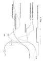
Die Figur 1 zeigt schematisch das Bremssystem eines Fahrzeugs. Die Figur 2 stellt das Ausführungsbeispiel anhand eines Ablaufdiagramms dar, während in der Figur 3 zeitliche Verläufe zu sehen sind.Figure 1 shows schematically the braking system of a vehicle. FIG. 2 shows the exemplary embodiment on the basis of a Flow diagram represents, while in Figure 3 temporal Gradients can be seen.
Die Erfindung wird im folgenden anhand eines Ausführungsbeispiels
dargestellt. Die Figur 1 zeigt mit dem Bezugszeichen
11a bis d vier Räder eines zweiachsigen Fahrzeugs, wobei jedes
Rad einen mit dem Bezugszeichen 12a bis d gekennzeichneten
Raddrehzahlsensor aufweist. Die Raddrehzahlen Nij werden
der Auswerteeinheit 16 zugeführt. Der Index i bezeichnet dabei
die Zugehörigkeit der entsprechenden Größe zur Vorder-(i
= v) bzw. zur Hinterachse (i = h). Der Index j repräsentiert
die Zugehörigkeit der entsprechenden Größe zur rechten (j =
r) bzw. zur linken (j = l) Fahrzeugseite.The invention is described below using an exemplary embodiment
shown. Figure 1 shows the
Jedem Rad 11a bis d sind Radbremsen 13a bis d zugeordnet,
deren Bremskraft bzw. Bremswirkung durch die Leitungen 15a
bis d von der Auswerteeinheit 16 gesteuert wird. Hierzu dienen
die Ansteuersignale Aij.
Mit dem Bezugszeichen 17 ist das vom Fahrer betätigbare
Bremspedal dargestellt. Die Stellung des Bremspedals 17 wird
erfasst und als Signal B der Auswerteeinheit 16 zugeführt.
Liegt ein Bremsvorgang vor, so werden durch das Signal BLS
die Bremslichter 18 angesteuert.
Erfindungsgemäß wird ein steiles Anbremsen (schnelle und starke Betätigung des Bremspedals 17) bzw. eine Panikbremsung anhand der Radreaktion erfasst. Hierzu ist in der Figur 2 ist ein Ablaufdiagramm zu sehen.According to the invention, a steep braking (fast and strong application of the brake pedal 17) or panic braking based on the wheel reaction. This is shown in the figure 2 is a flow chart.
Nach dem Startschritt 201 werden im Schritt 202 die Raddrehzahlen
Nij eingelesen. Im Schritt 203 wird ein Bezugsrad
ausgewählt. Um eine möglichst schnelle Erkennung zu gewährleisten,
wird jeweils das langsamste Rad außerhalb einer Antiblockierregelung
des Fahrzeugs ausgewählt. Dabei werden
Räder mit Drehzahlfühlerfehler, Plausibilitätsfehler, Einstreuung
oder stehende Räder bei der Auswahl des langsamsten
Rades nicht berücksichtigt. Hierzu kann auf die in Antiblokkiersystemen
im Allgemeinen vorhandene Sicherheitslogik zurückgegriffen
werden. Ebenfalls wird die Panikbremserkennung
nicht aktiviert bei erkanntem Schlechtweg oder Fahrbahnschwellen,
wo ein ähnlicher Radverlauf wie bei einer Panikbremsung
zustande kommen kann. Bei der Schlechtwegerkennung
kann ebenfalls auf eine in der Regel im Antiblockiersystem
vorhandene Schlechtwegkennung zurückgegriffen werden.After the
Alternativ oder ergänzend hierzu kann die Geschwindigkeitsauswahl auf die Nichtantriebsachse begrenzt werden. Damit wird der Einfluß von Motorschleppmoment, insbesondere auf Fahrbahnen mit einem niedrigen Reibwert, zusätzlich ausgeschlossen.Alternatively or in addition to this, the speed selection be limited to the non-drive axis. In order to the influence of engine drag torque, especially on Roads with a low coefficient of friction, additionally excluded.
Im folgenden Schritt 204 wird Geschwindigkeit Nb des nach
obigen Verfahren ausgewählten Rades differenziert gemäß
Um leichte Radstörungen auszugleichen kann die so gewonnene Verzögerung PT1-gefiltert werden. Der Filterzeitparameter ist dabei applizierbar.In order to compensate for slight wheel disturbances, the one obtained in this way Delay PT1 filtered. The filter time parameter can be applied.
Im Schritt 205 wird die (unter Umständen gefilterte) Radbeschleunigung
ab mit dem Schwellenwert SW1 verglichen. Im
Bremsfall ist der Wert ab der Radbeschleunigung negativ
(Radverzögerung). Ebenso ist der Schwellenwert SW1 (Verzögerungstriggerschwelle)
negativ. In
Unterschreitet die Radbeschleunigung ab den SW1 nicht, so
wird zum Endschritt 211 gegangen, da keine signifikant große
Radverzögerung vorliegt.If the wheel acceleration a b does not fall below the SW1, the process goes to the
Bei Erreichen der Verzögerungstriggerschwelle SW1 (beispielsweise
-1m/s2), also bei einem Unterschreiten von SW1,
wird der Zeitzähler ΔT im Schritt 206 gestartet.When the delay trigger threshold SW1 (for example -1m / s 2 ) is reached, that is when the value falls below SW1, the time counter ΔT is started in
Wird innerhalb des applizierbaren Zeitfensters ΔT (beispielsweise
50ms, Schritt 208) auch der zweite Schwellenwert
SW2 (beispielsweise -3m/s2) unterschritten (Schritt 207), so
wird zum Schritt 209 übergegangen. Im Schritt 208a wird die
Radbeschleunigung ab aktualisiert. Wird die Fahrzeugverzögerungsschwelle
SW2 [z.B. -3m/s2] nicht erreicht oder erst
nach Ablauf des Zeitfensters ΔT (z.B. 50ms), wird zum Endschritt
211 gegangen.If within the applicable time window ΔT (for example 50 ms, step 208) the second threshold value SW2 (for example -3 m / s 2 ) is also undershot (step 207), then a transition is made to step 209. In
Im Schritt 209 können noch weitere Bedingungen überprüft
werden, ehe im Schritt 210 eine Panikbremsung erkannt wird.
So können beispielsweise im Schritt 209 zusätzliche Plausibiliätsprüfungen
stattfinden, wie z.B., ob der Bremslichtschalter
(Signal BLS) betätigt ist (Fahrer steht auf der
Bremse) und/oder die Gesamtfahrzeugverzögerung ebenfalls von
Programmzyklus zu Programmzyklus größer wird.Further conditions can be checked in
In der Figur 3 sind die zeitlichen Verläufe verschiedener Größen beispielhaft aufgezeigt. Links oben ist zunächst der Verlauf der zeitlichen Änderung ab der Radgeschwindigkeit des Bezugsrades im Falle einer Panikbremsung sowie die Schwellenwerte SW1 und SW2 zu sehen. FIG. 3 shows an example of the time profiles of different sizes. Above left, the course of the change in time a b of the wheel speed of the reference wheel in the event of panic braking and the threshold values SW1 and SW2 can be seen.
Weiterhin sind der Verlauf der Fahrzeugverzögerung a_1, der Bremsdruckverlauf p_Hx an einer Hinterradbremse mit und ohne Panikbremserkennung sowie das Panikbremserkennung-Flag zu sehen.Furthermore, the course of the vehicle deceleration a_1 is the Brake pressure curve p_Hx on a rear wheel brake with and without Panic brake detection and the panic brake detection flag too see.
Hat der Wert ab innerhalb der Zeit ΔT den Schwellenwert SW2 unterschritten, so wird das Panikbremserkennung-Flag gesetzt (Schritt 210).If the value a b has fallen below the threshold value SW2 within the time ΔT, the panic brake detection flag is set (step 210).
Wird nun im Schritt 210 eine Panikbremsung erkannt, so wird
eine einstellbare, beispielsweise sehr flache, Pulsreihe zur
Raddruckgradientenbegrenzung (Ventilbetätigung ABS-Hydraulik)
an den Radbremsen der Hinterachse gestartet (siehe
Raddruckverlauf in der Figur 3). Diese Gradientenbegrenzung
läuft so lange, bis eine ABS-Regelung oder eine EBV-Regelung
(elektrische Bremskraftverteilung) an der Hinterachse
die Druckmodulation übernimmt, oder bis eine Fahrzeugmindestverzögerung
(z.B. -2m/s2) unterschritten oder eine
maximale Aufbauzeit z.B. (200ms) überschritten wurde.If panic braking is now detected in
Ferner kann für eine applizierbare Zeit die Panikbremsung dem nachfolgenden Verkehr angezeigt werden, indem beispielsweise die Warnblinkanlage angesteuert wird.Furthermore, panic braking can be carried out for an applicable time following traffic are displayed, for example by the hazard warning lights are activated.
Claims (11)
Applications Claiming Priority (4)
| Application Number | Priority Date | Filing Date | Title |
|---|---|---|---|
| DE10031125 | 2000-06-30 | ||
| DE10031125 | 2000-06-30 | ||
| DE10044121A DE10044121A1 (en) | 2000-06-30 | 2000-09-07 | Method and device for detecting panic braking |
| DE10044121 | 2000-09-07 |
Publications (3)
| Publication Number | Publication Date |
|---|---|
| EP1167143A2 true EP1167143A2 (en) | 2002-01-02 |
| EP1167143A3 EP1167143A3 (en) | 2002-10-02 |
| EP1167143B1 EP1167143B1 (en) | 2010-12-01 |
Family
ID=26006204
Family Applications (1)
| Application Number | Title | Priority Date | Filing Date |
|---|---|---|---|
| EP01113777A Expired - Lifetime EP1167143B1 (en) | 2000-06-30 | 2001-06-06 | Method and device for emergency braking detection |
Country Status (3)
| Country | Link |
|---|---|
| US (1) | US6623090B2 (en) |
| EP (1) | EP1167143B1 (en) |
| JP (1) | JP5091375B2 (en) |
Families Citing this family (9)
| Publication number | Priority date | Publication date | Assignee | Title |
|---|---|---|---|---|
| WO2002048581A1 (en) * | 2000-12-11 | 2002-06-20 | Bombardier Inc. | Virtual braking system for hydrostatically driven vehicle |
| JP4554166B2 (en) * | 2003-04-07 | 2010-09-29 | トヨタ自動車株式会社 | Brake control device for vehicle |
| FI20040276A (en) * | 2004-02-23 | 2005-08-24 | Tom Aalto | Procedure for improving control of the car and the situation in an emergency or full braking situation |
| DE102004018949A1 (en) * | 2004-04-20 | 2005-11-17 | Daimlerchrysler Ag | Method and device for controlling braking means of a vehicle |
| DE102004021174A1 (en) * | 2004-04-30 | 2005-11-24 | Daimlerchrysler Ag | Method for controlling a safety-relevant component of a motor vehicle and motor vehicle with a preventive triggering safety system |
| JP5125944B2 (en) * | 2008-09-25 | 2013-01-23 | トヨタ自動車株式会社 | Brake control device |
| US9434364B2 (en) | 2011-02-18 | 2016-09-06 | Advics Co., Ltd. | Braking control device for vehicle and braking control method for vehicle |
| DE102013220582A1 (en) * | 2013-10-11 | 2015-04-16 | Continental Teves Ag & Co. Ohg | Method for operating a brake system |
| CN104002676A (en) * | 2014-06-04 | 2014-08-27 | 温州大学 | Automobile accelerator wrong-pressing judgment method based on DSP2812 controller |
Citations (1)
| Publication number | Priority date | Publication date | Assignee | Title |
|---|---|---|---|---|
| DE19524939A1 (en) | 1995-07-08 | 1997-01-09 | Bosch Gmbh Robert | Method and device for controlling the brake system of a vehicle |
Family Cites Families (14)
| Publication number | Priority date | Publication date | Assignee | Title |
|---|---|---|---|---|
| JPS55110648A (en) * | 1979-02-16 | 1980-08-26 | Hitachi Ltd | Skid control device by use of microcomputer |
| US4398260A (en) * | 1979-05-18 | 1983-08-09 | Hitachi, Ltd. | Skid control method |
| JPH04118350A (en) * | 1990-09-07 | 1992-04-20 | Aisin Seiki Co Ltd | Anti-skid control device |
| JPH04201772A (en) * | 1990-11-30 | 1992-07-22 | Mazda Motor Corp | Antiskid brake device for vehicle |
| JP3424965B2 (en) * | 1993-09-22 | 2003-07-07 | 株式会社日立ユニシアオートモティブ | Anti-skid control device |
| JPH07195976A (en) * | 1993-12-29 | 1995-08-01 | Mitsubishi Electric Corp | Stoplight control device for vehicle |
| JP3724053B2 (en) * | 1996-04-26 | 2005-12-07 | トヨタ自動車株式会社 | Braking force control device |
| JP3528419B2 (en) * | 1996-04-26 | 2004-05-17 | トヨタ自動車株式会社 | Braking force control device |
| JP3684757B2 (en) * | 1997-06-05 | 2005-08-17 | 日産自動車株式会社 | Brake fluid pressure control device for vehicle |
| JPH1148951A (en) * | 1997-08-08 | 1999-02-23 | Toyota Motor Corp | Braking hydraulic pressure controller |
| US6023221A (en) * | 1997-08-25 | 2000-02-08 | Michelotti; Paul E | System to activate automobile hazard warning lights |
| JP3692777B2 (en) * | 1998-05-27 | 2005-09-07 | 日産自動車株式会社 | Braking assist device for vehicle |
| DE19936436A1 (en) * | 1999-03-04 | 2001-01-04 | Continental Teves Ag & Co Ohg | Procedure for recognizing an emergency braking situation |
| US6212461B1 (en) * | 1999-05-28 | 2001-04-03 | General Motors Corporation | Extended brake switch software for vehicle stability enhancement system |
-
2001
- 2001-06-06 EP EP01113777A patent/EP1167143B1/en not_active Expired - Lifetime
- 2001-06-20 JP JP2001186189A patent/JP5091375B2/en not_active Expired - Fee Related
- 2001-07-02 US US09/897,009 patent/US6623090B2/en not_active Expired - Lifetime
Patent Citations (1)
| Publication number | Priority date | Publication date | Assignee | Title |
|---|---|---|---|---|
| DE19524939A1 (en) | 1995-07-08 | 1997-01-09 | Bosch Gmbh Robert | Method and device for controlling the brake system of a vehicle |
Also Published As
| Publication number | Publication date |
|---|---|
| JP2002037041A (en) | 2002-02-06 |
| US6623090B2 (en) | 2003-09-23 |
| US20020027389A1 (en) | 2002-03-07 |
| EP1167143A3 (en) | 2002-10-02 |
| EP1167143B1 (en) | 2010-12-01 |
| JP5091375B2 (en) | 2012-12-05 |
Similar Documents
| Publication | Publication Date | Title |
|---|---|---|
| EP1574400B1 (en) | Method for actuating a reversible occupant protection system in a motor vehicle | |
| DE19901953B4 (en) | Device and method for stabilizing a vehicle combination | |
| EP1142768B1 (en) | Method for preventing the overturning of a vehicle about its longitudinal axis | |
| EP1601561B1 (en) | Method and system for controlling the driving stability of a vehicle and use of said system | |
| DE19933084B4 (en) | Method and device for controlling the slip of a vehicle wheel | |
| DE4418070C1 (en) | Method for comparing wheel speeds for a motor vehicle | |
| EP1687183A1 (en) | Method and device for reducing damage caused by an accident | |
| DE60126025T2 (en) | Warning device and method for a vehicle | |
| EP2257453A1 (en) | Adaptive cruise control system | |
| DE19814574A1 (en) | Generation of signals for control of road vehicle brake lights | |
| DE19949286B4 (en) | Device and method for controlling at least one vehicle movement variable | |
| DE19708508A1 (en) | Method and device for regulating a movement quantity representing the movement of the vehicle | |
| DE102010029223B4 (en) | Brake assistant for motor vehicles with improved braking effect | |
| DE102011077153B4 (en) | Method for modifying a vehicle stability control system and electronic control unit | |
| EP1045783B1 (en) | Device and method for limiting a backward rolling speed of a motor vehicle | |
| DE19738611A1 (en) | Emergency vehicle braking method using obstacle detection system - involves detecting obstacles, and only when collision is unavoidable by steering/braking, established by evaluation unit, is automatic emergency braking applied | |
| EP1131235B1 (en) | Method and device for stabilising a vehicle equipped with a slip-controlled brake system | |
| DE19958772A1 (en) | Method and device for traction control (ASR) of a motor vehicle depending on the curve radius and lateral acceleration | |
| EP1167143A2 (en) | Method and device for emergency braking detection | |
| DE10031128B4 (en) | Method and device for recognizing a lane change | |
| DE19834167B4 (en) | Method and device for adjusting the braking power to current wheel-road-traction conditions | |
| EP0844954B1 (en) | Method and device for controlling a vehicle brake system | |
| EP0859712A1 (en) | Method and device for adjusting an amount of movement representing the vehicle motion | |
| EP1571058A1 (en) | Braking method for a vehicle | |
| DE10044121A1 (en) | Method and device for detecting panic braking |
Legal Events
| Date | Code | Title | Description |
|---|---|---|---|
| PUAI | Public reference made under article 153(3) epc to a published international application that has entered the european phase |
Free format text: ORIGINAL CODE: 0009012 |
|
| AK | Designated contracting states |
Kind code of ref document: A2 Designated state(s): AT BE CH CY DE DK ES FI FR GB GR IE IT LI LU MC NL PT SE TR |
|
| AX | Request for extension of the european patent |
Free format text: AL;LT;LV;MK;RO;SI |
|
| PUAL | Search report despatched |
Free format text: ORIGINAL CODE: 0009013 |
|
| AK | Designated contracting states |
Kind code of ref document: A3 Designated state(s): AT BE CH CY DE DK ES FI FR GB GR IE IT LI LU MC NL PT SE TR |
|
| AX | Request for extension of the european patent |
Free format text: AL;LT;LV;MK;RO;SI |
|
| 17P | Request for examination filed |
Effective date: 20030402 |
|
| AKX | Designation fees paid |
Designated state(s): DE ES GB SE |
|
| 17Q | First examination report despatched |
Effective date: 20070302 |
|
| GRAP | Despatch of communication of intention to grant a patent |
Free format text: ORIGINAL CODE: EPIDOSNIGR1 |
|
| RIC1 | Information provided on ipc code assigned before grant |
Ipc: B60T 8/17 20060101AFI20100728BHEP |
|
| GRAS | Grant fee paid |
Free format text: ORIGINAL CODE: EPIDOSNIGR3 |
|
| GRAA | (expected) grant |
Free format text: ORIGINAL CODE: 0009210 |
|
| AK | Designated contracting states |
Kind code of ref document: B1 Designated state(s): DE ES GB SE |
|
| REG | Reference to a national code |
Ref country code: GB Ref legal event code: FG4D Free format text: NOT ENGLISH |
|
| REF | Corresponds to: |
Ref document number: 50115723 Country of ref document: DE Date of ref document: 20110113 Kind code of ref document: P |
|
| REG | Reference to a national code |
Ref country code: SE Ref legal event code: TRGR |
|
| REG | Reference to a national code |
Ref country code: ES Ref legal event code: FG2A Ref document number: 2355961 Country of ref document: ES Kind code of ref document: T3 Effective date: 20110401 |
|
| PLBE | No opposition filed within time limit |
Free format text: ORIGINAL CODE: 0009261 |
|
| STAA | Information on the status of an ep patent application or granted ep patent |
Free format text: STATUS: NO OPPOSITION FILED WITHIN TIME LIMIT |
|
| 26N | No opposition filed |
Effective date: 20110902 |
|
| REG | Reference to a national code |
Ref country code: DE Ref legal event code: R097 Ref document number: 50115723 Country of ref document: DE Effective date: 20110902 |
|
| PGFP | Annual fee paid to national office [announced via postgrant information from national office to epo] |
Ref country code: ES Payment date: 20120628 Year of fee payment: 12 |
|
| PGFP | Annual fee paid to national office [announced via postgrant information from national office to epo] |
Ref country code: GB Payment date: 20130620 Year of fee payment: 13 |
|
| GBPC | Gb: european patent ceased through non-payment of renewal fee |
Effective date: 20140606 |
|
| PG25 | Lapsed in a contracting state [announced via postgrant information from national office to epo] |
Ref country code: GB Free format text: LAPSE BECAUSE OF NON-PAYMENT OF DUE FEES Effective date: 20140606 |
|
| REG | Reference to a national code |
Ref country code: ES Ref legal event code: FD2A Effective date: 20150728 |
|
| PG25 | Lapsed in a contracting state [announced via postgrant information from national office to epo] |
Ref country code: ES Free format text: LAPSE BECAUSE OF NON-PAYMENT OF DUE FEES Effective date: 20140607 |
|
| PGFP | Annual fee paid to national office [announced via postgrant information from national office to epo] |
Ref country code: SE Payment date: 20160621 Year of fee payment: 16 |
|
| REG | Reference to a national code |
Ref country code: SE Ref legal event code: EUG |
|
| PG25 | Lapsed in a contracting state [announced via postgrant information from national office to epo] |
Ref country code: SE Free format text: LAPSE BECAUSE OF NON-PAYMENT OF DUE FEES Effective date: 20170607 |
|
| PGFP | Annual fee paid to national office [announced via postgrant information from national office to epo] |
Ref country code: DE Payment date: 20190822 Year of fee payment: 19 |
|
| REG | Reference to a national code |
Ref country code: DE Ref legal event code: R119 Ref document number: 50115723 Country of ref document: DE |
|
| PG25 | Lapsed in a contracting state [announced via postgrant information from national office to epo] |
Ref country code: DE Free format text: LAPSE BECAUSE OF NON-PAYMENT OF DUE FEES Effective date: 20210101 |