EP1208978B1 - Dosiervorrichtung mit elastischem Band für eine Druckmaschine - Google Patents
Dosiervorrichtung mit elastischem Band für eine Druckmaschine Download PDFInfo
- Publication number
- EP1208978B1 EP1208978B1 EP01126514A EP01126514A EP1208978B1 EP 1208978 B1 EP1208978 B1 EP 1208978B1 EP 01126514 A EP01126514 A EP 01126514A EP 01126514 A EP01126514 A EP 01126514A EP 1208978 B1 EP1208978 B1 EP 1208978B1
- Authority
- EP
- European Patent Office
- Prior art keywords
- cylinder
- elastic
- roller
- belt
- dosing belt
- Prior art date
- Legal status (The legal status is an assumption and is not a legal conclusion. Google has not performed a legal analysis and makes no representation as to the accuracy of the status listed.)
- Expired - Lifetime
Links
Images
Classifications
-
- B—PERFORMING OPERATIONS; TRANSPORTING
- B41—PRINTING; LINING MACHINES; TYPEWRITERS; STAMPS
- B41F—PRINTING MACHINES OR PRESSES
- B41F31/00—Inking arrangements or devices
- B41F31/16—Continuous, e.g. endless, band apparatus
-
- G—PHYSICS
- G10—MUSICAL INSTRUMENTS; ACOUSTICS
- G10L—SPEECH ANALYSIS TECHNIQUES OR SPEECH SYNTHESIS; SPEECH RECOGNITION; SPEECH OR VOICE PROCESSING TECHNIQUES; SPEECH OR AUDIO CODING OR DECODING
- G10L19/00—Speech or audio signals analysis-synthesis techniques for redundancy reduction, e.g. in vocoders; Coding or decoding of speech or audio signals, using source filter models or psychoacoustic analysis
- G10L2019/0001—Codebooks
- G10L2019/0003—Backward prediction of gain
-
- G—PHYSICS
- G10—MUSICAL INSTRUMENTS; ACOUSTICS
- G10L—SPEECH ANALYSIS TECHNIQUES OR SPEECH SYNTHESIS; SPEECH RECOGNITION; SPEECH OR VOICE PROCESSING TECHNIQUES; SPEECH OR AUDIO CODING OR DECODING
- G10L19/00—Speech or audio signals analysis-synthesis techniques for redundancy reduction, e.g. in vocoders; Coding or decoding of speech or audio signals, using source filter models or psychoacoustic analysis
- G10L2019/0001—Codebooks
- G10L2019/0011—Long term prediction filters, i.e. pitch estimation
-
- Y—GENERAL TAGGING OF NEW TECHNOLOGICAL DEVELOPMENTS; GENERAL TAGGING OF CROSS-SECTIONAL TECHNOLOGIES SPANNING OVER SEVERAL SECTIONS OF THE IPC; TECHNICAL SUBJECTS COVERED BY FORMER USPC CROSS-REFERENCE ART COLLECTIONS [XRACs] AND DIGESTS
- Y10—TECHNICAL SUBJECTS COVERED BY FORMER USPC
- Y10S—TECHNICAL SUBJECTS COVERED BY FORMER USPC CROSS-REFERENCE ART COLLECTIONS [XRACs] AND DIGESTS
- Y10S101/00—Printing
- Y10S101/33—Ink transfer employing one or more belts
Definitions
- the present invention relates to an apparatus and a method for applying paint or other solutions to a plate cylinder or a picture element of a printing press according to the preamble of claims 1 and 16.
- Printing machines in particular offset printing machines typically have a plate cylinder on which an imaged plate is stretched. During printing, the plate is inked and the inked image transferred to a blanket, which then contacts paper in sheet form or in the form of an endless paper web.
- the ink for the plate cylinder can be transferred from a fountain roller to a paint roller through a series of metering rollers or metering belts. From the inking roller, the color is transferred to the plate cylinder.
- a method for color dosing of the ductor roller on the inking rollers uses vibrating rollers or metering rollers with slip gap.
- metering by squeegee rollers or metering rollers with slip gap can result in discontinuous ink transfer.
- both lifter and metering rolls have a specific slip between the roll surfaces during the transfer process.
- the Czech patent no. 248128 discloses an inking unit with a flexible and elastic band.
- the paint is applied as a uniform, wide strip on the flexible and elastic band.
- Two tension rollers are connected to an automatic tension control, which, according to the patent, move away from one another to form a thinner ink layer and move toward each other to form a thicker ink layer.
- One of the tension rollers is contacted by a press roller.
- the device of the Czech patent no. 248128 has the disadvantage that the tension rollers, the pressure roller and the automatic tension control device require that a path of the belt be increased or decreased, to change the color thickness when the automatic tension control varies a distance between the two tension rollers. Changing the path length of a flexible, elastic band requires a complicated arrangement and could lead to increased band failures. Moreover, the tensioner is a complex assembly requiring tension rollers and press rollers to provide sufficient tension in the elastic band.
- the publication DE 3516570 shows a device for controlling the speed of a printing tape.
- An object of the present invention is to provide an accurate and reliable apparatus and method for continuously metering ink or other solution to a printing press.
- a device for applying paint or other solution according to the invention consists of a first roller, a second roller and an elastic band which passes over the first roller and the second roller during operation, wherein the first roller has a lower surface speed than the second roller having.
- the second roller has a higher surface speed than the first roller and will henceforth also be referred to as a high-speed roller, while the first roller is referred to as a low-speed roller.
- the elastic bands are arranged such that each elastic band preferably passes only around a low speed roller and a high speed roller.
- the band can be guided around the first and second rollers in such a way that the length of the band is fixed in this way, i. is essentially consistent.
- path of fixed length in the present document means that the Path length of the belt does not change significantly as the belt goes through its path, although slight deviations could occur due to the stretching and contraction of the belt.
- the elastic band of the present invention With the elastic band of the present invention, a discontinuous transfer of color can be avoided. Also, the elastic band avoids the specific slippage that may occur during the transfer process. As a result, the present invention offers the advantage of a continuous, slip-free color dosage. In addition, due to the elasticity of the band, the elastic band can be deformed by the different surface speeds of the rollers.
- the belt does not slip either on the first or on the second roller.
- the slip-free contact leads to a more uniform printing.
- slack-free means that although micro creep may occur, the belt does not slip so that the speed of the belt is not significantly changed with respect to the surface speed of the roller.
- a device according to the invention which can also be referred to as a dosing device, can be arranged so that it can contact another elastic band at a gap.
- the elastic bands have a color film on the outer surface.
- the thickness of the ink film is in inverse proportion to the amount of tension in the elastic band.
- the elastic bands expand and become thinner as they leave the lower surface speed roll, while contracting and becoming thicker as they leave the higher surface speed roll.
- Elastic bands have the advantage that they can deform in response to the load caused by the different speeds of the rollers.
- the deformation of the elastic bands changes the surface of the elastic band, thereby changing the thickness of the ink film brought about and the distribution of the color on subsequent devices is influenced. Since the rollers have different surface speeds, the surface speed of the elastic bands varies.
- the radius of the first roller is preferably, though not necessarily, smaller than the radius of the second roller.
- the different radii offer the advantage of changing the surface speeds of the rollers, which in turn affects the deformation of the elastic band.
- the rollers may then have the same rotational frequency, which may allow for simpler drive mechanisms, for example 1: 1. It could also be used rolls of the same size, if they are driven at different rotational frequencies.
- the present invention may include a ductor roller that contacts one of the low speed rollers to form a gap therewith.
- the ductor roller has the advantage that the color film can be transferred to the elastic band.
- the present invention may also include an inking roller that contacts one of the high speed rollers to form a gap therewith.
- the present invention may also include a printing cylinder, such as a plate cylinder, which directly contacts the inking roller or the high speed roller to form a nip.
- a method according to the invention for applying paint or another solution to a printing cylinder by moving an elastic belt over a first roller and a second roller and applying the paint or the other solution to the elastic belt comprises the following steps: rotating the first roller at a first surface speed, rotating the second roller at a second surface speed, wherein the first surface speed is higher than the second surface speed.
- the first roller and the second roller are preferably driven rollers.
- the present invention may also be used to apply dampening solution or other liquids to be applied to a cylinder in a printing press or to a web of material.
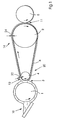
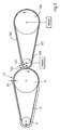
- FIG. 1 shows a side view of a first embodiment of a metering device according to the present invention.
- a fountain roller 1 can receive ink from an ink fountain 10 and transfer the ink to a belt 6 on a first drum 4.
- the elastic band 6 passes around the roller 4 and a second roller 2, preferably in a slip-free manner.
- the roller 4 has a lower surface speed and a smaller radius than the roller 2.
- a low-speed ink film 12 is transferred from the fountain roller 1 to the outer surface of the elastic belt 6 at a nip 3.
- the higher surface speed of the roller 2 increases the surface speed of the elastic band 6, thereby providing a high-speed portion 14 of the elastic band 6.
- the Surface of the high-speed portion 14 of the elastic belt 6 becomes larger, and the ink film 12 becomes thinner in response to the increase in the surface speed.
- the roller 4 and the roller 2 can be driven by a single motor.
- the roller 4 can be driven directly by a shaft of the motor and the roller 2 with the motor shaft to be geared technically.
- the roller 2 and the roller 4 may each be driven by a separate motor.
- the ink can then be transferred to a paint roller 5 at a gap 11.
- the roller 4 reduces the surface speed of the elastic band 6, thereby providing a low-speed portion 20.
- the surface of the low-speed portion 20 of the elastic belt 6 becomes smaller, and any remaining ink film 12 becomes thicker in response to the speed reduction.
- V s / (1 + ⁇ s ) V f / (1 + ⁇ f )
- V s the surface velocity for the low speed section 20
- V f the surface area velocity for the high speed section 14
- ⁇ s the strain constant for the low speed section 20
- ⁇ f the strain constant for the high speed section 14.
- Fig. 2 shows two dosing belts, which are arranged one behind the other and can apply even thinner color films to an inking roller.
- the elastic band 6 of the first embodiment may contact a second elastic band 100 at a contact gap 102 between the elastic bands formed by the second roller 2 and a third roller 104.
- the rotation of the first roller 4 and the second roller 2 drives the elastic belt 6 in the clockwise direction, while the rotation of the third roller 104 and a fourth roller 106 drives the second elastic belt 100 in a direction opposite to the direction of the elastic belt 6 is, ie in this example counterclockwise.
- the ink film 12 is transferred from the elastic band 6 to the second elastic band 100 at the contact gap 102 between the elastic bands.
- the resulting ink film 101 is then transferred to the high-speed roll 106 and thinned by the belt 100 in a similar manner as by the belt 6.
- the ink may be transferred to a paint roller or to another belt.
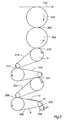
- Fig. 3 shows a side view of four metering belts, as shown in Fig. 1, which are arranged serially one behind the other.
- a fountain roller 258 may transfer ink to a first metering belt 200 at a first nip 202 which is formed by a lower speed roller 41 to form the ink film 12.
- the ink film 12 is then transferred to a second metering belt 204 at a second nip 206 in the same manner as described in FIG. 2.
- the ink film 12 is transferred to a third metering belt 210 at a third contact nip 212 in the same manner as described in FIG.
- the ink film 12 is transferred to a fourth metering belt 214 at a fourth nip 216 in the same manner as described in FIG.
- the ink film 12 may be transferred to the plate cylinder 256.
- the plate cylinder 256 which may belong to a printing unit of an offset printing press
- the inked image may be transferred to a blanket cylinder 220 at a nip 260 formed by the plate cylinder 256 and the blanket cylinder 220.
- the blanket cylinder 220 may then transfer the image to a web 222 of a substrate, such as paper.
- the gaps 202, 206, 212, 216, 218, 260 may be slip-free contact gaps.
- the elastic metering belts 200, 204, 210, 214 rotate in opposite directions to each other.
- the elastic band 200 may rotate counterclockwise while the elastic band 204 may rotate clockwise, rotate the band 210 counterclockwise, and rotate the elastic band 214 in a clockwise direction.
- the fountain roller 258 can rotate counter to the rotation of belt 6, ie clockwise.
- the plate cylinder 256 may rotate counter to the rotation of the belt 214, for example, counterclockwise, and the blanket cylinder 220 may rotate the ink roller 256 in an opposite manner, for example, in a clockwise direction.
- the elastic bands may be made of rubber, for example.
Landscapes
- Inking, Control Or Cleaning Of Printing Machines (AREA)
- Coating Apparatus (AREA)
- Application Of Or Painting With Fluid Materials (AREA)
- Rotary Presses (AREA)
- Printing Methods (AREA)
Applications Claiming Priority (2)
| Application Number | Priority Date | Filing Date | Title |
|---|---|---|---|
| US716693 | 2000-11-20 | ||
| US09/716,693 US6513429B1 (en) | 2000-11-20 | 2000-11-20 | Elastic belt metering device for a printing press |
Publications (2)
| Publication Number | Publication Date |
|---|---|
| EP1208978A1 EP1208978A1 (de) | 2002-05-29 |
| EP1208978B1 true EP1208978B1 (de) | 2007-07-11 |
Family
ID=24879038
Family Applications (1)
| Application Number | Title | Priority Date | Filing Date |
|---|---|---|---|
| EP01126514A Expired - Lifetime EP1208978B1 (de) | 2000-11-20 | 2001-11-13 | Dosiervorrichtung mit elastischem Band für eine Druckmaschine |
Country Status (5)
| Country | Link |
|---|---|
| US (1) | US6513429B1 (enExample) |
| EP (1) | EP1208978B1 (enExample) |
| JP (1) | JP4051199B2 (enExample) |
| AT (1) | ATE366662T1 (enExample) |
| DE (2) | DE50112705D1 (enExample) |
Families Citing this family (5)
| Publication number | Priority date | Publication date | Assignee | Title |
|---|---|---|---|---|
| DE10202785B4 (de) * | 2002-01-25 | 2011-12-01 | Manroland Ag | Druckmaschine mit einem Farb- und Feuchtwerk |
| US20100050890A1 (en) * | 2008-08-28 | 2010-03-04 | Goss International Americas, Inc. | Infinitely variable cutoff printing press |
| US20100083856A1 (en) * | 2008-10-03 | 2010-04-08 | Goss International Americas, Inc. | Belted inker for a printing press |
| WO2013113376A1 (en) * | 2012-01-31 | 2013-08-08 | Hewlett-Packard Indigo Bv | To apply a coating to media |
| CN113043718B (zh) * | 2021-03-22 | 2022-10-11 | 中国美术学院 | 一种印刷设备及其印刷方法 |
Family Cites Families (13)
| Publication number | Priority date | Publication date | Assignee | Title |
|---|---|---|---|---|
| GB280376A (en) | 1926-12-02 | 1927-11-17 | Arthur Crompton | Improvements relating to fabric printing machines |
| DE459469C (de) | 1927-01-05 | 1928-05-07 | Julius Fischer Fa | Farbtuch fuer Walzendruckmaschinen |
| DE519889C (de) | 1930-05-29 | 1931-03-05 | Julius Fischer Fa | Farbwerk fuer Tapetendruck- und aehnliche Maschinen |
| DE558045C (de) | 1930-07-06 | 1932-09-03 | Otto Melliger | Handdruckapparat |
| US3363530A (en) * | 1965-06-07 | 1968-01-16 | Eastman Kodak Co | Apparatus for processing film by means of a porous web solution applicator |
| US4016812A (en) * | 1975-06-13 | 1977-04-12 | Lauk David V | Device for cleaning ink from a printing apparatus |
| DE3308067C1 (de) * | 1983-03-08 | 1984-09-13 | M.A.N.- Roland Druckmaschinen AG, 6050 Offenbach | Fluessigkeitszufuehrvorrichtung fuer Farbe und Feuchtfluessigkeit einer Rotationsflachdruckmaschine |
| GB2160820A (en) | 1984-05-08 | 1986-01-02 | Isowa Industry Co | Method of controlling speed of printing belt and device therefor |
| DE3531433A1 (de) | 1985-09-03 | 1987-03-12 | Heidelberger Druckmasch Ag | Farbwerk fuer rotationsdruckmaschinen |
| DD278552A1 (de) | 1988-12-23 | 1990-05-09 | Polygraph Leipzig | Farbwerk fuer schnellaufende rotationsdruckmaschinen |
| JP3412361B2 (ja) * | 1995-01-30 | 2003-06-03 | ノーリツ鋼機株式会社 | 写真焼付現像処理装置 |
| US6367380B1 (en) * | 1998-02-02 | 2002-04-09 | Sequa Can Machinery, Inc. | Inking system with a belt and differential roller speeds |
| AU2572399A (en) | 1998-02-02 | 1999-08-16 | Sequa Corporation | Inking system with a belt and differential roller speeds |
-
2000
- 2000-11-20 US US09/716,693 patent/US6513429B1/en not_active Expired - Fee Related
-
2001
- 2001-11-13 DE DE50112705T patent/DE50112705D1/de not_active Expired - Lifetime
- 2001-11-13 AT AT01126514T patent/ATE366662T1/de not_active IP Right Cessation
- 2001-11-13 EP EP01126514A patent/EP1208978B1/de not_active Expired - Lifetime
- 2001-11-13 DE DE10155682A patent/DE10155682A1/de not_active Withdrawn
- 2001-11-20 JP JP2001355117A patent/JP4051199B2/ja not_active Expired - Fee Related
Also Published As
| Publication number | Publication date |
|---|---|
| JP2002200740A (ja) | 2002-07-16 |
| JP4051199B2 (ja) | 2008-02-20 |
| US6513429B1 (en) | 2003-02-04 |
| ATE366662T1 (de) | 2007-08-15 |
| DE50112705D1 (de) | 2007-08-23 |
| DE10155682A1 (de) | 2002-07-04 |
| EP1208978A1 (de) | 2002-05-29 |
Similar Documents
| Publication | Publication Date | Title |
|---|---|---|
| DE8413874U1 (de) | Vorrichtung zum Befeuchten an lithographischen Druckpressen | |
| EP1208978B1 (de) | Dosiervorrichtung mit elastischem Band für eine Druckmaschine | |
| EP0093879A1 (de) | Verfahren und Vorrichtung zum Dosieren der Farbe bei Offsetdruckmaschinen | |
| DE10023935A1 (de) | Kurzfarbwerk einer Rotationsdruckmaschine | |
| DE10058841B4 (de) | Verfahren zur Regelung eines Umfangsregisters | |
| DE4028417A1 (de) | Farbbewege-/reibwalze | |
| EP0778128B1 (de) | Antrieb für mehrere Übertragungszylinder einer Druckmaschine | |
| EP1291176B1 (de) | Druckmaschine und Verfahren zum Betreiben eines Farbwerks | |
| DE3239114A1 (de) | Druckmaschine | |
| EP0893251B1 (de) | Druckmaschine mit einem Feuchtwerk | |
| DE2360988B1 (de) | Vorrichtung zur Ermittlung der Zügigkeit von Farben, insbesondere Druckfarben | |
| EP0115301A2 (de) | Kurzfarbwerk | |
| EP0028421B1 (de) | Farbwerk für eine Druckmaschine | |
| DE10335758C5 (de) | Verfahren und Druckwerk zur Beeinflussung der lateralen Bahnspreizung insbesondere an Rotationsdruckmaschinen | |
| DE3644982C2 (enExample) | ||
| EP0518084A1 (de) | Offsetdruckerpresse mit gesteuerter Emulsionsbildung | |
| DE102010015628B4 (de) | Verfahren zur Drehzahlsteuerung von Walzen in einer Druckmaschine | |
| DE112005000433T5 (de) | Druckfarbenausformwalzenantrieb zur Verbesserung der Druckqualität | |
| EP0065138B1 (de) | Kurzfarbwerk für eine Druckmaschine | |
| DE4314426A1 (de) | Verfahren zur Farbmengeneinstellung bei Heberfarbwerken von Druckmaschinen, insbesondere Bogenoffsetdruckmaschinen, sowie entsprechend ausgebildetes Heberfarbwerk | |
| EP1037746B1 (de) | Bahnführungswalze | |
| DD202663A5 (de) | Farbwerk fuer eine lithographische druckmaschine | |
| DE4411109C1 (de) | Verfahren zur Farbmengeneinstellung bei Heberfarbwerken von Druckmaschinen, insbesondere Bogenoffsetdruckmaschinen, sowie entsprechend ausgebildetes Heberfarbwerk | |
| EP0845354A3 (de) | Farbkasten für Rotationsdruckmaschinen | |
| DE20213169U1 (de) | Druckeinheiten mit mindestens zwei zusammen wirkenden Walzen sowie Vorrichtungen zur Ermittlung eines Abrollverhaltens einer elastischen Schicht |
Legal Events
| Date | Code | Title | Description |
|---|---|---|---|
| PUAI | Public reference made under article 153(3) epc to a published international application that has entered the european phase |
Free format text: ORIGINAL CODE: 0009012 |
|
| 17P | Request for examination filed |
Effective date: 20020306 |
|
| AK | Designated contracting states |
Kind code of ref document: A1 Designated state(s): AT BE CH CY DE DK ES FI FR GB GR IE IT LI LU MC NL PT SE TR |
|
| AX | Request for extension of the european patent |
Free format text: AL;LT;LV;MK;RO;SI |
|
| AKX | Designation fees paid |
Designated state(s): AT BE CH CY DE DK ES FI FR GB GR IE IT LI LU MC NL PT SE TR |
|
| RAP1 | Party data changed (applicant data changed or rights of an application transferred) |
Owner name: GOSS INTERNATIONAL AMERICAS, INC. |
|
| 17Q | First examination report despatched |
Effective date: 20050310 |
|
| GRAP | Despatch of communication of intention to grant a patent |
Free format text: ORIGINAL CODE: EPIDOSNIGR1 |
|
| GRAS | Grant fee paid |
Free format text: ORIGINAL CODE: EPIDOSNIGR3 |
|
| GRAA | (expected) grant |
Free format text: ORIGINAL CODE: 0009210 |
|
| AK | Designated contracting states |
Kind code of ref document: B1 Designated state(s): AT BE CH CY DE DK ES FI FR GB GR IE IT LI LU MC NL PT SE TR |
|
| REG | Reference to a national code |
Ref country code: GB Ref legal event code: FG4D Free format text: NOT ENGLISH |
|
| REG | Reference to a national code |
Ref country code: CH Ref legal event code: EP |
|
| REF | Corresponds to: |
Ref document number: 50112705 Country of ref document: DE Date of ref document: 20070823 Kind code of ref document: P |
|
| REG | Reference to a national code |
Ref country code: IE Ref legal event code: FG4D Free format text: LANGUAGE OF EP DOCUMENT: GERMAN |
|
| GBT | Gb: translation of ep patent filed (gb section 77(6)(a)/1977) |
Effective date: 20071017 |
|
| REG | Reference to a national code |
Ref country code: CH Ref legal event code: NV Representative=s name: KIRKER & CIE S.A. |
|
| ET | Fr: translation filed | ||
| PG25 | Lapsed in a contracting state [announced via postgrant information from national office to epo] |
Ref country code: FI Free format text: LAPSE BECAUSE OF FAILURE TO SUBMIT A TRANSLATION OF THE DESCRIPTION OR TO PAY THE FEE WITHIN THE PRESCRIBED TIME-LIMIT Effective date: 20070711 Ref country code: NL Free format text: LAPSE BECAUSE OF FAILURE TO SUBMIT A TRANSLATION OF THE DESCRIPTION OR TO PAY THE FEE WITHIN THE PRESCRIBED TIME-LIMIT Effective date: 20070711 Ref country code: ES Free format text: LAPSE BECAUSE OF FAILURE TO SUBMIT A TRANSLATION OF THE DESCRIPTION OR TO PAY THE FEE WITHIN THE PRESCRIBED TIME-LIMIT Effective date: 20071022 Ref country code: PT Free format text: LAPSE BECAUSE OF FAILURE TO SUBMIT A TRANSLATION OF THE DESCRIPTION OR TO PAY THE FEE WITHIN THE PRESCRIBED TIME-LIMIT Effective date: 20071211 |
|
| NLV1 | Nl: lapsed or annulled due to failure to fulfill the requirements of art. 29p and 29m of the patents act | ||
| REG | Reference to a national code |
Ref country code: IE Ref legal event code: FD4D |
|
| PG25 | Lapsed in a contracting state [announced via postgrant information from national office to epo] |
Ref country code: GR Free format text: LAPSE BECAUSE OF FAILURE TO SUBMIT A TRANSLATION OF THE DESCRIPTION OR TO PAY THE FEE WITHIN THE PRESCRIBED TIME-LIMIT Effective date: 20071012 Ref country code: DK Free format text: LAPSE BECAUSE OF FAILURE TO SUBMIT A TRANSLATION OF THE DESCRIPTION OR TO PAY THE FEE WITHIN THE PRESCRIBED TIME-LIMIT Effective date: 20070711 |
|
| PLBE | No opposition filed within time limit |
Free format text: ORIGINAL CODE: 0009261 |
|
| STAA | Information on the status of an ep patent application or granted ep patent |
Free format text: STATUS: NO OPPOSITION FILED WITHIN TIME LIMIT |
|
| PG25 | Lapsed in a contracting state [announced via postgrant information from national office to epo] |
Ref country code: IE Free format text: LAPSE BECAUSE OF FAILURE TO SUBMIT A TRANSLATION OF THE DESCRIPTION OR TO PAY THE FEE WITHIN THE PRESCRIBED TIME-LIMIT Effective date: 20070711 |
|
| BERE | Be: lapsed |
Owner name: GOSS INTERNATIONAL AMERICAS, INC. Effective date: 20071130 |
|
| 26N | No opposition filed |
Effective date: 20080414 |
|
| PG25 | Lapsed in a contracting state [announced via postgrant information from national office to epo] |
Ref country code: SE Free format text: LAPSE BECAUSE OF FAILURE TO SUBMIT A TRANSLATION OF THE DESCRIPTION OR TO PAY THE FEE WITHIN THE PRESCRIBED TIME-LIMIT Effective date: 20071011 Ref country code: MC Free format text: LAPSE BECAUSE OF NON-PAYMENT OF DUE FEES Effective date: 20071130 |
|
| PG25 | Lapsed in a contracting state [announced via postgrant information from national office to epo] |
Ref country code: BE Free format text: LAPSE BECAUSE OF NON-PAYMENT OF DUE FEES Effective date: 20071130 |
|
| PG25 | Lapsed in a contracting state [announced via postgrant information from national office to epo] |
Ref country code: AT Free format text: LAPSE BECAUSE OF NON-PAYMENT OF DUE FEES Effective date: 20071113 |
|
| PG25 | Lapsed in a contracting state [announced via postgrant information from national office to epo] |
Ref country code: CY Free format text: LAPSE BECAUSE OF FAILURE TO SUBMIT A TRANSLATION OF THE DESCRIPTION OR TO PAY THE FEE WITHIN THE PRESCRIBED TIME-LIMIT Effective date: 20070711 |
|
| PG25 | Lapsed in a contracting state [announced via postgrant information from national office to epo] |
Ref country code: LU Free format text: LAPSE BECAUSE OF NON-PAYMENT OF DUE FEES Effective date: 20071113 |
|
| PG25 | Lapsed in a contracting state [announced via postgrant information from national office to epo] |
Ref country code: TR Free format text: LAPSE BECAUSE OF FAILURE TO SUBMIT A TRANSLATION OF THE DESCRIPTION OR TO PAY THE FEE WITHIN THE PRESCRIBED TIME-LIMIT Effective date: 20070711 |
|
| PGFP | Annual fee paid to national office [announced via postgrant information from national office to epo] |
Ref country code: FR Payment date: 20101202 Year of fee payment: 10 |
|
| PG25 | Lapsed in a contracting state [announced via postgrant information from national office to epo] |
Ref country code: IT Free format text: LAPSE BECAUSE OF NON-PAYMENT OF DUE FEES Effective date: 20071130 |
|
| PGFP | Annual fee paid to national office [announced via postgrant information from national office to epo] |
Ref country code: CH Payment date: 20101124 Year of fee payment: 10 Ref country code: DE Payment date: 20101126 Year of fee payment: 10 |
|
| PGFP | Annual fee paid to national office [announced via postgrant information from national office to epo] |
Ref country code: GB Payment date: 20101124 Year of fee payment: 10 |
|
| REG | Reference to a national code |
Ref country code: CH Ref legal event code: PL |
|
| GBPC | Gb: european patent ceased through non-payment of renewal fee |
Effective date: 20111113 |
|
| PG25 | Lapsed in a contracting state [announced via postgrant information from national office to epo] |
Ref country code: LI Free format text: LAPSE BECAUSE OF NON-PAYMENT OF DUE FEES Effective date: 20111130 Ref country code: CH Free format text: LAPSE BECAUSE OF NON-PAYMENT OF DUE FEES Effective date: 20111130 |
|
| REG | Reference to a national code |
Ref country code: FR Ref legal event code: ST Effective date: 20120731 |
|
| REG | Reference to a national code |
Ref country code: DE Ref legal event code: R119 Ref document number: 50112705 Country of ref document: DE Effective date: 20120601 |
|
| PG25 | Lapsed in a contracting state [announced via postgrant information from national office to epo] |
Ref country code: GB Free format text: LAPSE BECAUSE OF NON-PAYMENT OF DUE FEES Effective date: 20111113 |
|
| PG25 | Lapsed in a contracting state [announced via postgrant information from national office to epo] |
Ref country code: FR Free format text: LAPSE BECAUSE OF NON-PAYMENT OF DUE FEES Effective date: 20111130 |
|
| PG25 | Lapsed in a contracting state [announced via postgrant information from national office to epo] |
Ref country code: DE Free format text: LAPSE BECAUSE OF NON-PAYMENT OF DUE FEES Effective date: 20120601 |