EP1201589A2 - Vorrichtung zum Transportieren von Bogenmaterial mit höhenverstellbaren Taschen - Google Patents
Vorrichtung zum Transportieren von Bogenmaterial mit höhenverstellbaren Taschen Download PDFInfo
- Publication number
- EP1201589A2 EP1201589A2 EP01124279A EP01124279A EP1201589A2 EP 1201589 A2 EP1201589 A2 EP 1201589A2 EP 01124279 A EP01124279 A EP 01124279A EP 01124279 A EP01124279 A EP 01124279A EP 1201589 A2 EP1201589 A2 EP 1201589A2
- Authority
- EP
- European Patent Office
- Prior art keywords
- gear
- rod
- height
- ring
- Prior art date
- Legal status (The legal status is an assumption and is not a legal conclusion. Google has not performed a legal analysis and makes no representation as to the accuracy of the status listed.)
- Granted
Links
- 238000000034 method Methods 0.000 claims abstract description 13
- 230000007246 mechanism Effects 0.000 claims description 11
- 230000008569 process Effects 0.000 claims description 7
- 230000000630 rising effect Effects 0.000 claims description 6
- 230000008859 change Effects 0.000 description 5
- 230000009471 action Effects 0.000 description 4
- 230000003993 interaction Effects 0.000 description 3
- 230000008901 benefit Effects 0.000 description 2
- 210000003746 feather Anatomy 0.000 description 2
- 230000001174 ascending effect Effects 0.000 description 1
- 210000001520 comb Anatomy 0.000 description 1
- 230000003750 conditioning effect Effects 0.000 description 1
- 230000008878 coupling Effects 0.000 description 1
- 238000010168 coupling process Methods 0.000 description 1
- 238000005859 coupling reaction Methods 0.000 description 1
- 238000006073 displacement reaction Methods 0.000 description 1
- 230000000694 effects Effects 0.000 description 1
- 230000036316 preload Effects 0.000 description 1
- 230000000284 resting effect Effects 0.000 description 1
- 230000001960 triggered effect Effects 0.000 description 1
Images







Classifications
-
- B—PERFORMING OPERATIONS; TRANSPORTING
- B65—CONVEYING; PACKING; STORING; HANDLING THIN OR FILAMENTARY MATERIAL
- B65H—HANDLING THIN OR FILAMENTARY MATERIAL, e.g. SHEETS, WEBS, CABLES
- B65H39/00—Associating, collating, or gathering articles or webs
- B65H39/02—Associating,collating or gathering articles from several sources
-
- B—PERFORMING OPERATIONS; TRANSPORTING
- B65—CONVEYING; PACKING; STORING; HANDLING THIN OR FILAMENTARY MATERIAL
- B65H—HANDLING THIN OR FILAMENTARY MATERIAL, e.g. SHEETS, WEBS, CABLES
- B65H2301/00—Handling processes for sheets or webs
- B65H2301/40—Type of handling process
- B65H2301/43—Gathering; Associating; Assembling
- B65H2301/432—Gathering; Associating; Assembling in pockets, i.e. vertically
- B65H2301/4321—Gathering; Associating; Assembling in pockets, i.e. vertically and dropping material through bottom of the pocket
-
- B—PERFORMING OPERATIONS; TRANSPORTING
- B65—CONVEYING; PACKING; STORING; HANDLING THIN OR FILAMENTARY MATERIAL
- B65H—HANDLING THIN OR FILAMENTARY MATERIAL, e.g. SHEETS, WEBS, CABLES
- B65H2403/00—Power transmission; Driving means
- B65H2403/40—Toothed gearings
- B65H2403/41—Rack-and-pinion, cogwheel in cog railway
-
- B—PERFORMING OPERATIONS; TRANSPORTING
- B65—CONVEYING; PACKING; STORING; HANDLING THIN OR FILAMENTARY MATERIAL
- B65H—HANDLING THIN OR FILAMENTARY MATERIAL, e.g. SHEETS, WEBS, CABLES
- B65H2403/00—Power transmission; Driving means
- B65H2403/40—Toothed gearings
- B65H2403/47—Ratchet
-
- B—PERFORMING OPERATIONS; TRANSPORTING
- B65—CONVEYING; PACKING; STORING; HANDLING THIN OR FILAMENTARY MATERIAL
- B65H—HANDLING THIN OR FILAMENTARY MATERIAL, e.g. SHEETS, WEBS, CABLES
- B65H2403/00—Power transmission; Driving means
- B65H2403/70—Clutches; Couplings
- B65H2403/72—Clutches, brakes, e.g. one-way clutch +F204
- B65H2403/722—Gear clutches
-
- B—PERFORMING OPERATIONS; TRANSPORTING
- B65—CONVEYING; PACKING; STORING; HANDLING THIN OR FILAMENTARY MATERIAL
- B65H—HANDLING THIN OR FILAMENTARY MATERIAL, e.g. SHEETS, WEBS, CABLES
- B65H2511/00—Dimensions; Position; Numbers; Identification; Occurrences
- B65H2511/10—Size; Dimensions
- B65H2511/15—Height, e.g. of stack
-
- B—PERFORMING OPERATIONS; TRANSPORTING
- B65—CONVEYING; PACKING; STORING; HANDLING THIN OR FILAMENTARY MATERIAL
- B65H—HANDLING THIN OR FILAMENTARY MATERIAL, e.g. SHEETS, WEBS, CABLES
- B65H2511/00—Dimensions; Position; Numbers; Identification; Occurrences
- B65H2511/20—Location in space
- B65H2511/22—Distance
Definitions
- the present invention relates generally to a transport device for sheet material, for example for conveying newspapers, and in particular a transport device for Sheet material with pockets moving along a path.
- the present invention further relates to such bags and a method for transporting of such bags.
- US 5,911,416 describes a transport device for sheet material that has a variety of pockets which can be moved along a path and which serve to store sheet material from To accommodate sheet material feeders. These bags make it possible to Example that a first outer part of a newspaper from a first sheet material feeder first placed in the pockets and then an inner part of the Newspaper is inserted between the folds of the first outer part of the newspaper.
- the device described in US 5,911,416 uses a lifting cam to move one semi-circular actuator to move such that a drive shaft in a way is rotated that a height for that on a rack arranged feet of the bag is adjusted.
- the opening of the pockets is done by a Locking gear prevented. Then the sheet material can be picked up and placed in the Bags are put down.
- the locking mechanism can then be switched by a cam be solved.
- the rack is moved to a lower position by a pre-tension spring lowered so that the feet are released by a driver cam. So that can Sheet material in the pockets can be taken from these on the bottom, then on to be transported or stacked.
- US 5,251,888 describes pockets which can be moved along an endless path. Every bag comes with two vertically adjustable stops provided on a bag carrying device are slidably attached. A guide element is adjustable so that it Stops can adjust vertically when the bags move along the endless path become.
- the object of the present invention is a less time-consuming one Work step to create comprehensive adjustment device for each bag.
- the present invention comprises a transport device for sheet material, the one Contains a plurality of pockets, each of which has an adjusting device for adjusting the Pocket height to define a set height, the Adjustment device an adjusting rod, a ring gear, the outer surface of which with the adjusting rod is connected, and comprises a locking ring which can be detached from the ring gear, wherein the control rod a release device for releasing the locking ring from the ring gear during an adjustment process.
- the present invention enables the bags to be moved by a single movement Example by sliding the control rod to set it to an adjustment height and to work continuously at this height. The operator needs the locking ring not discontinued.
- a reset station is also provided, this being a movable, rising one Includes feedback ramp, which is then also set to the new height and also can have a locking device.
- Each pocket can have a sliding gear that is connected to the ring gear in a rotationally fixed manner included, which can optionally be released from the locking ring, so that on this allows an optional release of the ring gear from the locking ring.
- the locking ring is preferably a single tooth ratchet, the pocket preferably contains a pawl that constantly interacts with the locking ring, except if the bag bottom is open during the release process.
- the adjusting rod preferably has two predetermined notches for height marking, the allow the operator to adjust the height settings of the bags to two different ones Set values, for example for sheet material of 26.5 cm (10.5 inches) and 30.5 cm (12 inches). But there can also be other height settings on the control rod be provided.
- the notches can, for example, with a in the rod holder the provided ball lock interact, this rod holder with the Pocket wall is connected.
- a second rod holder is preferably provided.
- the release device of the control rod preferably contains at least one raised one Cam part that the sliding gear in relation to the locking ring to the outside shifts.
- the locking ring is released from the sliding gear that it can rotate with respect to the ring gear and the sliding gear.
- the locking ring is then held in the blocked state by the pawl during the Adjusting rod adjusts the pockets to a different height by turning the ring wheel. If this new height is reached, the cam part no longer acts on the displaceable Gear so that this by the action of a spring with the locking ring back in Is engaged to lock the bags at the newly set height.
- the control rod can contain a fine adjustment device, for example by the Effect of an adjusting screw arranged between two rod parts.
- the one The adjusting rod can be continuously adjusted to different heights be curved and rotatable, the disengaging device an axially extending cam blade, which between a star wheel and the locking ring is arranged.
- the cam blade moves the displaceable one Gear in such a way that the locking ring is released. So if an operator's pocket height wants to change, he turns the control rod to release the sliding gear, and then he moves the control rod axially to change the pocket height.
- the ring gear preferably has a first outer toothed part which with a is engaged by a spring biased semicircular gear, and one second outer toothed part which is engaged with the control rod.
- the ring gear is via an inner star wheel rotatably connected to the sliding gear, the Slidable gear is rotatably connected to the shaft through which the Pocket height can be adjusted.
- the locking ring also encloses the shaft, whereby the Slidable gear can optionally be engaged with the locking ring by the Slidable gear is moved axially with respect to the shaft. If the locking ring attacks on the sliding gear, then both elements lead a common Rotary motion.
- the sliding gear from the locking ring through Moving the sliding gear using a cam or one Is released the locking ring is freely rotatable around the shaft, whereas the slidable gear remains rotatable with respect to the shaft and the ring gear.
- the semicircular gear is preferably spring loaded in one direction, what causes the fingers to fall to the bottom of the bag and trigger a release.
- the Loosening the pawl and thus the locking ring in the release station causes this The fingers release the sheet material in the pocket.
- the present invention further provides a sheet material bag;
- the Sheet material pocket includes a first wall and a second wall spaced therefrom Wall, which together define a receiving area for sheet material, at least a finger movable with respect to the first wall, which defines a pocket bottom, the at least one finger being detachable for opening the pocket bottom, a shaft, which is connected to move the at least one finger Slidable gear that is rotatable and axially displaceable with respect to the shaft Ring gear that is rotationally fixed with respect to the sliding gear, and a locking ring that is selectively engageable with the slidable gear.
- a displaceable adjusting rod preferably combs the ring gear and comprises one Release device on.
- the release device contains a raised cam to move the sliding gear
- the Disengaging device in a second embodiment comprises a cam blade, which by Turning the control rod is actuated.
- the control rod is preferably displaceable in a first and a second holder arranged, these brackets are fixedly connected to the first wall.
- One of the first and second brackets can have a ball lock, which with in the Adjusting rod provided adjustment notches interact, these notches correspond to different pocket heights.
- the control rod is moved between at least two predetermined positions, whereby preferably a ball lock in the rod holder into a notch on the rod locks.
- the moving step preferably includes the use of a raised cam, to move the gear axially.
- the gear is preferably a slidable Gear that interacts with a ring gear, the ring gear meshing the rod.
- the step of moving may alternatively include rotating the rod, with a Push the cam blade away from a locking ring of the locking mechanism becomes.
- rod is defined here to include any elongated element can.
- sliding gear is specifically defined here to mean every comprises slidable coupling element, and can also have gears with an outer Include star gears, an outer single longitudinal key or tooth, or each another type with which a ring gear can be connected in a rotationally fixed manner and on which a locking ring is either attachable or rotatable freely from it, one element one Has ball locking mechanism.
- FIG. 1 shows a schematic illustration of a transport device 105 for Sheet material with an endless web 101 for conveying a plurality of pockets 10 in one direction 17.
- Each pocket 10 contains fingers 90 which determine the height of the pocket, a height adjustment device 8 and provided for the individual adjustment of the height a releasable locking device 9 provided for the height adjustment device 8.
- each pocket 10 can be adjusted manually by means of the setting device 8 can be set, the fingers 90 for receiving folded products from a Starting position, for example 26.5 cm (10.5 inches), on at least one of two desired heights can be moved.
- the pockets are 10 during the adjustment process in the idle state, the setting also taking place outside the setting range can, for example, by operators moving along path 101.
- a another option is to drive the bags into the adjustment range that Stop the device and adjust each pocket.
- a robot that works with the adjustment device interacts, be arranged on the adjustment area 1, to move each bag to the correct height when a bag is in the adjustment range 1 is promoted and stopped there.
- the Adjustment device 8 engaged with a locked locking device 9, such as will still be described with reference to FIGS. 8 to 10, so that the pocket fingers 90 stay stationary. Then when all the pockets are set, the pockets become 10 in Movement set and under a first feed station 2 for sheet material, where to Example a folded sheet 6, a newspaper or other printed matter in the Pockets 10 is entered. At an optionally available second feed station 3 a second sheet part can be entered into the cover sheet 6 to make the finished produce inserted and collated printed matter 7.
- the pockets 10 can then be passed into a release station 4, which the Locking device 9 releases.
- the spring-loaded adjusting device 8 gives then the fingers 90 free so that the bottom of the pockets 10 opens and the products 7 for example on a conveyor belt 11.
- the pockets 10 After the pockets 10 have left the release station 4, they pass through one Reset station 5, which contains a movable ascending reset ramp 25 with a reset cam follower 156 of the adjusting device 8 and one Locking device 35 cooperates to lock the locking device 9.
- the pocket 10 has one upper rear wall 54, an upper front wall 52 and a side wall 44, wherein an opening 56 between the upper rear wall 54 and the upper front wall 52 located, which is used to hold sheet material.
- the bag 10 can still be a have lower rear wall 64 and a lower front wall 62.
- a rack 80 on the fingers 90 are mounted, is displaceable relative to the wall 52.
- the fingers 90 are on the rack 80 by means of a fixed to a first part 92 of the finger 90 Pivot pin 96 mounted.
- a second part 94 of the finger 90 serves one Define pocket bottom when fingers 90 are in the closed position are located.
- the rack 80 includes a toothing 82 (Fig.
- the pinions 120 are rotatably supported in the walls 44 and 46 Shaft 110 arranged.
- the wall 46 With the wall 46 (in FIG. 4 for the sake of a better one Clarity not fully shown) is an end 111 of the shaft 110 by Adjustment ring gear 140 guided, of which only a first part is shown in Fig. 3.
- the Ring gear 140 has an inner surface that ensures that it is non-rotatable Relation to a slidable gear 180 (Fig. 5), which in turn is rotationally fixed is connected to the shaft 110.
- the slidable gear 180 is relative to that Shaft 110 axially displaceable, so that it is connected to a locking ring 160 (visible inside the Ring gear 140 and only in Fig. 4) alternately mutually engaged, the Lock ring 160 is part of the locking device 9.
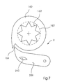
- the locking device 9 comprises also a pawl 209, which has a single tooth on the outside of the ring 160 interacts.
- the ring gear 140 is only partially shown in FIGS. 2, 3 and 4, wherein a second outer toothed area 182 (FIG. 5) is used with a (not shown) interacting control rod.
- FIGS. 5 and 6 The details of the sliding gear 180 and its interaction with the ring gear 140 and the locking ring 160 described in more detail below with reference to FIGS. 5 and 6.
- the Release cam 130 is set up so that it has a release surface 100 of the fingers 90 interacts.
- the release surface 100 is in an opening 86 between the Gears 82 arranged when the fingers 90 are completely lowered, so that the Fingers swung away from the rear wall and so those in the pockets 10 Products are released.
- the release of the fingers 90 is similar to the release of the feet in US 5,911,416.
- Fig. 4 shows a cooperating with a semicircular setting gear 150 Ring gear 140.
- a reset cam follower 156 On one side of the semicircular adjustment gear 150 is located a reset cam follower 156, which is mounted on an axis 154.
- the semicircular adjustment gear 150 is on a spring 158 attached, which biases the semicircular setting gear 150 in the direction 151, as can be seen in Fig. 2.
- FIG. 5 shows an exploded view of certain details of the adjustment device.
- the end 111 of the shaft 110 fits into the internally toothed bore 147 of the sliding gear 180, the end 111 through in the ring gear 140 and the Lock ring 160 passes through the inner bores.
- the end 111 is at one Screw 145 fastened, which is against the sliding gear 180 via a spring 146 supported.
- the slidable gear 180 against the force of the spring 146 in the Direction of arrow 240 are moved, with which slidable gear 180 is related is axially displaceable on the shaft 110, but always non-rotatably with the shaft 110 stays connected.
- the displaceable gear wheel 180 has an external star toothing 141, which with a inner star toothing of the ring gear 140 fits together. That way achieved that the sliding gear 180 and the ring gear 140 always together rotate.
- the inside of the sliding gear 180 and the ring gear 140 is Lock ring 160, the lock ring 160 via an inner star wheel 163 with an outer Star wheel 141 of the sliding gear 180 is selectively connectable if that Slidable gear 180 not in the axial direction against the spring force of the spring 146 is moved.
- the displaceable gear wheel 180 has a raised area 142, which is connected to a Release device of an actuating rod cooperates so that the sliding gear 180th can be moved against the spring force of the spring 146.
- the ring gear 140 has an external toothing 181 for cooperation with the semicircular gear 150 (Fig. 2), as well as an external toothing 182, which in the Adjusting rod 250 (Fig. 8) engages.
- the locking ring 160 is provided on an outer surface with a single tooth 164, which with the pawl 209 cooperates, as can be seen in FIG. 7.
- a protrusion 210 extends out of the pawl 209 so that the pawl 209 is between an upper and a lower position is movable.
- the pawl can be biased by a spring that it preferably occupies one position or jumps into one of the two positions.
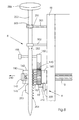
- a notch 251 of an adjusting rod 250 acts with one in a first setting Rod holder 301 held ball lock 303 together.
- the ball lock 303 a ball under spring tension, is preloaded so that one operator can can feel the setting, but axial displacement of the control rod 250 cannot is prevented if the control rod 250 with sufficient manual force is applied.
- the operator can grasping and pulling a handle 255, the operator can the adjusting rod 250 in relation to the holder 301 and to a second holder 302 Pull up, with both brackets attached to a side wall 46 of the bag.
- teeth 254 are provided, which with the Interacting teeth 182 of the ring gear 140.
- three of the Teeth 254 are partially or completely engaged with the toothing 182, so that the Ring gear 140 is rotatable to rotate the shaft 110 and thus move the fingers 90.
- An upward movement of the control rod 250 moves the fingers 90 down and vice versa.
- the Finger released and the bottom of the bag opens.
- a disengaging device 253 which in the 8 consists of a raised cam 253, which with a Inner surface of the raised portion 142 of the slidable gear 180 in Interaction.
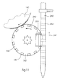
- Fig. 11 illustrates this upward movement 241, which causes the Ring gear 140 moves in direction 242, causing shaft 110 in the same direction is rotated and thus the rack 80 and the fingers 90 (Fig. 2) rotated downward become.
- Fig. 10 it is shown that the second setting is reached when a second Notch 252 has arrived at the ball lock 303. At the same time, the cam 253 the sliding gear 180 free, so that the locking ring 160 again with the slidable gear 180 is engaged.
- the setting rod 250 can be used to implement more than two settings, whereby for each additional setting requires a further cam and a further notch are.
- FIGS. 8 to 11 for easy manual changing of Pocket height offers a single one-step adjustment device.
- the simple push-pull movement ideal for the interposition of a robot suitable. So a robot arm can be used in station 1 Adjust pocket height of each pocket. To do this, each bag is transported, then stopped and the actuator rod 250 is gripped by the robot arm to the actuator rod to move a given distance.
- the actuator rod can be provided with a fine adjustment device 260, which consists of a There is a type of adjusting screw through which the distance between the notches 251, 252 on the one hand and the cam 253 on the other hand can be changed.
- the operator holds the lower part of the control rod 250 with one hand and rotates the upper part of the control rod 250, so as to change the distance.
- the upper part of the control rod 250 has a screw and the lower end a slide nut and an immovable housing for fine adjustment with just one hand enable.
- a tension spring can also be provided between the two parts to oppose the screwing force.
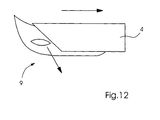
- Fig. 12 shows the release station 4, which the pawl 209 of the locking device 9 after moves down to an unlocked position when a pocket moves station 4 towards 17 passes.
- pawl 209 is removed from tooth 164 moved away.
- the lock ring 160 moves counterclockwise (Fig. 7). This counterclockwise movement occurs as a result of Spring preload of the semicircular gear 150 in direction 151 (FIG. 2), whereby the semicircular gear 150 is rotated counterclockwise (Fig. 2).
- the locking ring 160, the ring gear 140, the sliding gear 180 and the shaft 110 in the release station they are all rotatable with respect to each other, they rotate together.
- the shaft 110 moves the fingers 90 by means of the gear 122 and the rack 80 down until the cams 130 cause the fingers to open, causing the Release sheet material in the pocket 10.
- the pockets 10 are in a position A, as in FIG. 13 is shown, wherein the reset cam 156 is in an upper position. If the pocket 10 moves past the reset station 5, the reset cam 156 through the rising ramp 25 down to the originally set position B pressed. Since the return ramp 25 is set to the correct height, the Single tooth 164 of the locking ring 160 in the correct position on the bottom of the ramp 25, see above that a locking device 35 the projection 210 of the pawl 209 upwards moved and engages tooth 164. Thus, the pockets 10 are correct on the closed position has been deferred, so that another continuous operation can be carried out along the track 101 without a further stop or Standstill is required.
- the return ramp 25 should preferably be that of the common pocket height of all Bags set the appropriate height.
- the reset ramp 25 can be done in increments can be moved in the direction of 225. In this way, the return ramp 25 in a Position that a newly set pocket height for all pockets 10th equivalent.
- the dashed line in FIG. 13 shows a second position of the return ramp, which corresponds to a new pocket height.
- the cam 156 is not quite so so that the fingers are not raised so far, which increases the pocket height (depth) so that, for example, the height for folded 30.4 cm (12 inch) products instead of the previous 26.5 cm folded products (10.5 inches) is reset.
- the pawl engages 209 not directly on the single tooth. Thus the ring turns until the pawl attacks the single tooth. This rotation can damage the locking ring 160 (if the ramp is set too low) or there may be an incorrect pocket height can be set (if the ramp is set too high).
- the functional sequence of the device 100 can be summarized as follows: When the system is at a standstill, the actuating rod 250 can be 10 in at each pocket one of the two positions defined by the notches, in which the Ball 303 engages either in the notch 251 or 252, the pawl 209 on the Lock ring 160 attacks.
- the setting should be the same for each pocket 10. On in this way, all pockets 10 are locked in the desired set height.
- the rising ramp 25 is then set so that its height is the common height which corresponds to pockets.
- the pockets 10 then take up the sheet material from the feed stations 2 and 3. to Release the bags pass through the release station 4, which causes the Pawl 209 releases, so that the fingers move downward and thus the ordered or Release assembled sheet material 7.
- the pockets are then at the reset station 5 by the reset cam 156 by moving downward along ramp 25 around fingers 90 to bring it to the correct height.
- the locking device 35 then guides the pawl 209 back to lock the lock ring 160 and the fingers at the correct height lock.
- the Star toothing 141 releases the locking ring 160 (which is held in place by a pawl is held), as shown in Fig. 16.
- the control rod 350 can then by opening and Move pushed into a variety of positions to change pocket height become.
- the actuating rod 350 can then be turned back in the opposite direction to the direction 351 (or pushed back by the action of spring 146, the spring being the sliding gear 180 pushes in the opposite direction to direction 240) to the new one To lock the bag height.
- a display device, for example, on the semicircular adjustment gear 150 is provided, the actual position of the Show pocket height.
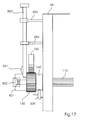
- the rod 850 is a cam rod which is one of the cams Has 253 similar cams 851 for releasing a star wheel 801 from the locking ring 160.
- the rod 850 moving up and down with respect to brackets 853 and 854 serves solely for releasing the star wheel 801 by causing the cam 851 to pull the star wheel 801 in Fig. 17 pushes to the left.
- the rod 860 is an articulated in a pivot bearing 861 Control rod, wherein the pivot bearing is connected to the pocket wall 46.
- the rod 860 has a lower end 863 and a worm gear 864.
- the lower end 863 is in the bracket 862 fixed to wall 46, bracket 862 being movable Has slot in which the lower end 863 move between two positions can.
- bracket 862 In the position where the worm gear 864 of the rod 860 is engaged, it is in engagement with the semicircular adjustment gear 150. If that Star wheel 801 is loosened by rod 850 and by moving rod 860 in direction 871 is rotated, the semicircular adjustment gear 150 can be turned by the worm gear 864 can be moved in such a way that a pocket height can be set. After the the desired height has been reached, the operator can set the 860 rod in the pivot position Turn 861 as indicated by arrows 870 and 872.
- tooth ratchet or “single tooth” is defined here to mean any type of Stop for a jack or a jack-like device may include.
- Locking ring is defined here to include any locking device.
Landscapes
- Sheets, Magazines, And Separation Thereof (AREA)
- Auxiliary Devices For And Details Of Packaging Control (AREA)
- Auxiliary Methods And Devices For Loading And Unloading (AREA)
- Pile Receivers (AREA)
- Supplying Of Containers To The Packaging Station (AREA)
Abstract
Description
- Verschieben eines Stabes, während die Tasche sich im Ruhezustand befindet, um die Finger der Tasche derart zu bewegen, dass die Tasche auf eine Einstellhöhe eingestellt wird,
- Bewegen eines Zahnrads durch den Stab in axiale Richtung, wodurch das Zahnrad auf diese Weise einen Verriegelungsmechanismus löst, der während des Einstellvorganges ortsfest bleibt, und
- das Wieder-Einrücken des Zahnrads in den Verriegelungsmechanismus.
Es zeigen:
- Fig. 1
- eine schematische Darstellung einer Transporteinrichtung für Bogenmaterial gemäß der vorliegenden Erfindung,
- Fig. 2
- einen Teil einer Tasche gemäß der vorliegenden Erfindung in Seitenansicht, wobei bestimmte Elemente aus Gründen der Übersichtlichkeit weg gelassen wurden,
- Fig. 3
- einen Teil einer Tasche gemäß der vorliegenden Erfindung in perspektivischer Darstellung, wobei bestimmte Elemente aus Gründen der Übersichtlichkeit weg gelassen wurden,
- Fig. 4
- einen Teil einer Tasche gemäß der vorliegenden Erfindung in einer weiteren perspektivischen Darstellung, wobei bestimmte Elemente aus Gründen der Übersichtlichkeit weg gelassen wurden,
- Fig. 5 und 6
- die Einstellvorrichtung zum Einstellen der Fingerhöhe gemäß der vorliegenden Erfindung in detaillierterer Darstellung,
- Fig. 7
- eine Detailansicht der Arretiervorrichtung nach Fig. 1,
- Fig. 8, 9 und 10
- einen Teil einer ersten Ausführungsform der Taschen gemäß Fig. 1 in Frontansicht,
- Fig. 11
- eine Detailansicht, die das Zusammenwirken der ersten Ausführungsform der Taschen in Fig. 11 darstellt,
- Fig. 12
- eine Detailansicht der Freigabestation nach Fig. 1,
- Fig. 13
- eine Detailansicht der Rückstellstation nach Fig. 1,
- Fig. 14 und 15
- eine Detailansicht einer zweiten Ausführungsform der Taschen nach Fig. 1 mit einem Nockenblattmechanismus,
- Fig. 16
- Details der zweiten Ausführungsform in Unteransicht,
- Fig. 17 und 18
- Detailansichten einer zweiten Ausführungsform, in der ein Zweistabmechanismus eingesetzt wird, wobei ein Stab ein Schneckenrad enthält.
- 1
- Einstellbereich
- 2, 3
- Zuführstation
- 4
- Freigabestation
- 5
- Rückstellstation
- 6
- Umschlagbogen/Bogen
- 7
- Bogenmaterial/Druckerzeugnis
- 8
- Einstellvorrichtung
- 9
- Arretiervorrichtung
- 10
- Tasche
- 11
- Förderband
- 17
- Bewegungsrichtung
- 25
- Rückstellrampe
- 35
- Verriegelungsvorrichtung
- 44
- Seitenwand
- 46
- Seitenwand
- 52
- vordere Wand
- 54
- Rückwand
- 56
- Öffnung
- 62
- untere vordere Wand
- 64
- untere Rückwand
- 80
- Zahnstange
- 82
- Verzahnung
- 86
- Öffnung
- 90
- Finger
- 92
- erster Teil eines Fingers
- 94
- zweiter Teil eines Fingers
- 96
- Schwenkzapfen
- 100
- Freigabefläche
- 101
- Bahn
- 102
- Anlage/Freigabefläche
- 105
- Transportvorrichtung
- 110
- Welle
- 111
- Ende (der Welle 110)
- 120
- Ritzel
- 122
- Zahnrad
- 130
- Freigabenocken
- 140
- Ringrad
- 141
- äußeres Sternrad (von 180)
- 142
- erhabener Bereich von 180
- 145
- Schraube
- 146
- Feder
- 147
- Bohrung (in 180)
- 150
- halbkreisförmiges Zahnrad
- 151
- Richtung
- 152
- Achse
- 154
- Achse
- 156
- Nockenstößel
- 158
- Feder
- 160
- Sperrring
- 162
- glatter Innenflächenbereich
- 163
- inneres Sternrad
- 164
- Einzelzahn des Sperrrings
- 180
- verschiebbares Zahnrad
- 181
- erster äußerer verzahnter Bereich
- 182
- zweiter äußerer verzahnter Bereich
- 209
- Sperrklinke
- 210
- Vorsprung
- 225
- Pfeil/Richtung
- 250, 350
- Stellstab
- 251, 252
- Kerben
- 253
- erhabener Nocken
- 254
- Zähne des Stellstabs
- 255
- Griff
- 260
- Feineinstellungsvorrichtung
- 301, 302 853, 854
- Stellstabhalterung
- 303
- Kugelarretierung
- 304
- ansteigende Fläche
- 351
- Drehrichtung des Stellstabs
- 353
- Nockenblatt
- 354
- ringförmige Zähne
- 801
- Sternrad
- 850
- Nockenstab
- 851
- Nocken
- 860
- Stellstab
- 861
- Drehlagerung
- 862
- Halterung
- 863
- unteres Ende
- 864
- Schneckenzahnrad
- 870, 871
- Drehrichtung
- A
- Position der Taschen
- B
- Position der Taschen
Claims (15)
- Transporteinrichtung für Bogenmaterial mit einer Vielzahl von Taschen (10), wobei jede Tasche eine Einstellvorrichtung (8) zum Einstellen der Höhe der Taschen (10) aufweist, die eine Einstellhöhe definiert,
dadurch gekennzeichnet, dass ein Stellstab (250, 350), insbesondere ein Nockenstab, und ein Ringrad (140) vorgesehen sind, wobei das Ringrad (140) eine Außenfläche aufweist, die mit dem Stellstab verbunden ist, und dass ein von dem Ringrad (140) lösbarer Sperrring (160) vorgesehen ist, wobei der Stellstab (250, 350) eine Ausrückvorrichtung zum Lösen des Sperrrings (160) von dem Ringrad (140) während des Einstellvorgangs aufweist. - Vorrichtung gemäß Anspruch 1,
dadurch gekennzeichnet, dass weiterhin eine Rückstellstation (5) vorgesehen ist, die eine bewegliche, ansteigende Rückstellrampe (25) und eine Verriegelungsvorrichtung (35) aufweist. - Vorrichtung gemäß Anspruch 1,
dadurch gekennzeichnet, dass weiterhin ein in Bezug auf den Sperrring (160) drehfestes verschiebbares Zahnrad (180) vorgesehen ist, das wahlweise von dem Sperrring (160) lösbar ist. - Vorrichtung gemäß Anspruch 1,
dadurch gekennzeichnet, dass der Sperrring (160) ein Einzahn-Zahngesperre (164) umfasst und die Tasche (10) weiterhin eine mit dem Sperrring (160) zusammenwirkende Klinke (209) umfasst. - Vorrichtung gemäß Anspruch 1,
dadurch gekennzeichnet, dass der Stellstab (250, 350) wenigstens zwei vorgegebene Kerben (251, 252) aufweist, die es dem Bediener ermöglichen, die Taschenhöhe auf zwei verschiedene Einstellungen einzustellen. - Vorrichtung gemäß Anspruch 5,
dadurch gekennzeichnet, dass die Kerben (251, 252) mit einer Stellstabhalterung (301, 302, 853, 854) zusammenwirken, wobei die Stellstabhalterung mit der Taschenwand (46) verbunden ist. - Vorrichtung gemäß Anspruch 1,
dadurch gekennzeichnet, dass der Stellstab (250) eine Feineinstellungsvorrichtung enthält. - Vorrichtung gemäß Anspruch 1,
dadurch gekennzeichnet, dass das Ringrad (140) einen ersten äußeren verzahnten Teil (181) aufweist, der mit einem durch eine Feder vorgespannten halbkreisförmigen Zahnrad (150) in Eingriff steht, und einen zweiten äußeren verzahnten Teil (182), der mit dem Stellstab (250) in Eingriff steht. - Vorrichtung gemäß Anspruch 8,
dadurch gekennzeichnet, dass das Ringrad (140) durch ein inneres Sternrad drehfest mit dem verschiebbaren Zahnrad (180) verbunden ist und das verschiebbare Zahnrad (180) drehfest mit einer Welle (110) verbunden ist. - Vorrichtung gemäß Anspruch 9,
dadurch gekennzeichnet, dass der Sperrring (160) die Welle (110) umschließt, wobei das verschiebbare Zahnrad (180) wahlweise mit dem Sperrring (160) in Eingriff steht, indem das verschiebbare Zahnrad (180) axial in Bezug auf die Welle (110) verschoben wird. - Vorrichtung gemäß Anspruch 1,
dadurch gekennzeichnet, dass die Einstellvorrichtung (8) einen Stellstab (860) und einen Nockenstab (850) enthält, wobei der Stellstab (860) durch eine Drehlagerung (861) angelenkt ist, die mit einer Tasche aus der Vielzahl von Taschen (10) verbunden ist. - Bogenmaterialtasche mitgekennzeichnet durcheiner ersten Wand (52),einer von der ersten Wand beabstandeten zweiten Wand (54), wobei der Bereich zwischen den Wänden einen Aufnahmebereich für Bogenmaterial (7) definiert,wenigstens einem in Bezug auf die erste Wand (52) beweglichen Finger (90), der einen Taschenboden definiert, wobei der wenigstens eine Finger (90) lösbar ist, so dass der Taschenboden geöffnet werden kann,eine Welle (110), die mit dem wenigstens einen Finger (90) zum Bewegen des wenigstens einen Fingers (90) verbunden ist,ein verschiebbares Zahnrad (180), das drehfest in Bezug auf die Welle (110) und verschiebbar in Bezug auf die Welle (110) ist,ein Ringrad (140), das fest in Bezug auf das verschiebbare Zahnrad (180) ist, undeinen Sperrring (160), der wahlweise mit dem verschiebbaren Zahnrad (180) in Eingriff bringbar ist.
- Bogenmaterialtasche gemäß Anspruch 12,
dadurch gekennzeichnet, dass weiterhin ein verschiebbarer Stellstab (250, 350) vorgesehen ist, der mit dem Ringrad (140) in Eingriff steht, wobei der Stellstab (250, 350) eine Ausrückvorrichtung aufweist. - Verfahren zum Einstellen der Höhe einer Bogenmaterialtasche,
gekennzeichnet durch
die folgenden Schritte:Verschieben eines Stellstabs bei im ruhenden Zustand befindlichen Taschen (10), um die Finger (90) der Tasche (10) zum Einstellen der Tasche auf eine eingestellte Höhe zu bewegen,Bewegen eines Zahnrads axial mit dem Stellstab derart, dass das Zahnrad einen Verriegelungsmechanismus löst, wobei der Verriegelungsmechanismus während des Einstellvorgangs ortsfest bleibt, undwieder Einrücken des Zahnrads in den Verriegelungsmechanismus. - Verfahren gemäß Anspruch 14,
dadurch gekennzeichnet, dass der Stellstab zwischen wenigstens zwei vorgegebenen Positionen bewegbar ist.
Applications Claiming Priority (2)
| Application Number | Priority Date | Filing Date | Title |
|---|---|---|---|
| US09/702,012 US6390469B1 (en) | 2000-10-30 | 2000-10-30 | Sheet material conveying apparatus with height-adjustable pockets |
| US702012 | 2000-10-30 |
Publications (3)
| Publication Number | Publication Date |
|---|---|
| EP1201589A2 true EP1201589A2 (de) | 2002-05-02 |
| EP1201589A3 EP1201589A3 (de) | 2004-03-24 |
| EP1201589B1 EP1201589B1 (de) | 2006-07-12 |
Family
ID=24819537
Family Applications (1)
| Application Number | Title | Priority Date | Filing Date |
|---|---|---|---|
| EP01124279A Expired - Lifetime EP1201589B1 (de) | 2000-10-30 | 2001-10-18 | Vorrichtung zum Transportieren von Bogenmaterial mit höhenverstellbaren Taschen |
Country Status (4)
| Country | Link |
|---|---|
| US (1) | US6390469B1 (de) |
| EP (1) | EP1201589B1 (de) |
| AT (1) | ATE332866T1 (de) |
| DE (1) | DE50110441D1 (de) |
Families Citing this family (4)
| Publication number | Priority date | Publication date | Assignee | Title |
|---|---|---|---|---|
| US6695306B2 (en) | 2002-06-24 | 2004-02-24 | Heidelberger Druckmaschinen Ag | Sheet material conveying apparatus with height-adjustable pockets |
| US7571902B2 (en) * | 2004-11-17 | 2009-08-11 | Goss International Americas, Inc. | Sheet material conveying apparatus with dual-bottom pockets |
| DE102017215314A1 (de) * | 2016-10-05 | 2018-04-05 | Heidelberger Druckmaschinen Ag | Druckmaschine mit einem Druckmodul aus zueinander justierbaren Submodulen |
| CN110065840B (zh) * | 2019-05-28 | 2024-06-11 | 佛山科学技术学院 | 一种传动辊间隙可自动调整的超薄带材传送机构 |
Family Cites Families (9)
| Publication number | Priority date | Publication date | Assignee | Title |
|---|---|---|---|---|
| US3891202A (en) * | 1972-05-01 | 1975-06-24 | Melvin D Kircher | Collating machine |
| CH594552A5 (de) * | 1976-02-19 | 1978-01-13 | Grapha Holding Ag | |
| CH594553A5 (de) | 1976-02-19 | 1978-01-13 | Grapha Holding Ag | |
| US4496141A (en) | 1982-12-17 | 1985-01-29 | Rockwell International Corporation | Method and apparatus for opening folded newspapers |
| CH681448A5 (de) | 1990-09-12 | 1993-03-31 | Grapha Holding Ag | |
| US5213318A (en) * | 1992-01-02 | 1993-05-25 | Am International Incorporated | Signature gatherer with light detector misfeed sensors |
| US5527025A (en) * | 1995-03-14 | 1996-06-18 | Am International, Inc. | Apparatus and method for forming sheet material assemblages |
| US5911416A (en) | 1996-09-25 | 1999-06-15 | Heidelberg Finishing Systems, Inc. | Variable height pocket for sheet material conveying apparatus |
| US6655681B1 (en) * | 2000-09-14 | 2003-12-02 | Heidelberger Druckmaschinen Ag | Sheet material conveying apparatus with individually-adjustable pockets |
-
2000
- 2000-10-30 US US09/702,012 patent/US6390469B1/en not_active Expired - Fee Related
-
2001
- 2001-10-18 DE DE50110441T patent/DE50110441D1/de not_active Expired - Lifetime
- 2001-10-18 AT AT01124279T patent/ATE332866T1/de not_active IP Right Cessation
- 2001-10-18 EP EP01124279A patent/EP1201589B1/de not_active Expired - Lifetime
Also Published As
| Publication number | Publication date |
|---|---|
| US6390469B1 (en) | 2002-05-21 |
| DE50110441D1 (de) | 2006-08-24 |
| EP1201589A3 (de) | 2004-03-24 |
| ATE332866T1 (de) | 2006-08-15 |
| EP1201589B1 (de) | 2006-07-12 |
Similar Documents
| Publication | Publication Date | Title |
|---|---|---|
| DE2706353C2 (de) | Einsteckmaschine | |
| DE2102187A1 (de) | Vorrichtung zum Entnehmen einzelner Gegenstände aus einem Stapel oder zum Stapeln von Gegenständen | |
| DE10319845A1 (de) | Verstellbare Greifvorrichtung für verstellbare Bogenaufnahmetaschen | |
| DE3026085A1 (de) | Variabler bogengeradeleger fuer eine papierzufuehrvorrichtung | |
| DE2346355A1 (de) | Bogendruckvorrichtung | |
| DE1028136B (de) | Buerodruckmaschine mit einer Vorrichtung zum Abdruck ausgewaehlter Stellen der Druckform | |
| CH629724A5 (de) | Falzmaschine mit einem schwertfalzwerk. | |
| EP1201589B1 (de) | Vorrichtung zum Transportieren von Bogenmaterial mit höhenverstellbaren Taschen | |
| AT523897A1 (de) | Transportbehälter mit einer Verschlussanordnung | |
| DE2702739C2 (de) | Einsteckmaschine | |
| DE1174331B (de) | Vorrichtung zum UEbertragen von Druckbildern von Druckformen auf befeuchtetes, bogen-foermiges Druckgut | |
| DE69204259T2 (de) | Automatisches Etikettiergerät für Netzsäcke oder ähnliche Behälter. | |
| DE681873C (de) | Rotationsumdruckmaschine zum ein- oder mehrzeiligen Bedrucken von befeuchteten Bogen | |
| EP1188702B1 (de) | Vorrichtung zum Transportieren von Bogenmaterial mit indivuell verstellbaren Taschen | |
| EP0597868A1 (de) | Vorrichtung zum einlegen und/oder entnehmen von gegenständen in/oder aus einer maschine. | |
| DE10322949A1 (de) | Verstellbare Greifvorrichtung für verstellbare Bogenaufnahmetaschen und Verfahren zur Verstellung von Bogenaufnahmetaschen | |
| EP1378473A2 (de) | Bogenmaterialtransportvorrichtung mit verstellbaren oberen greifern für Taschen | |
| DE1908166C3 (de) | Vorrichtung zum Geradstoßen von Papierbogen od dgl auf einem Ablage tisch, insbesondere fur eine Auslege einrichtung einer Druckmaschine | |
| CH696539A5 (de) | Bogenmaterialtransportvorrichtung mit höhenverstellbaren Taschen und zugehöriges Einstellverfahren. | |
| DE753696C (de) | Vorsteckvorrichtung fuer Schreib-, Schreibrechen-, Addier- oder aehnliche Maschinen | |
| DE631133C (de) | Einrichtung zur Zufuehrung von Bogen zu einer Maschine mit Papierwalze, z. B. Lochkartentabelliermaschine | |
| DE1942656C (de) | Vorschubapparat fur den schrittweisen Transport von bandförmigem Material | |
| DE674233C (de) | Verfahren und Vorrichtung zum ununterbrochenen Betrieb verschiedenartiger, mit unterschiedlicher Geschwindigkeit arbeitender Papierverarbeitungsmaschinen | |
| DE3417508A1 (de) | Kartoniervorrichtung | |
| DE3885894T2 (de) | Vorrichtung zum Verteilen kleiner Glasmengen in Formen zum Herstellen von Glasgegenständen. |
Legal Events
| Date | Code | Title | Description |
|---|---|---|---|
| PUAI | Public reference made under article 153(3) epc to a published international application that has entered the european phase |
Free format text: ORIGINAL CODE: 0009012 |
|
| AK | Designated contracting states |
Kind code of ref document: A2 Designated state(s): AT BE CH CY DE DK ES FI FR GB GR IE IT LI LU MC NL PT SE TR |
|
| AX | Request for extension of the european patent |
Free format text: AL;LT;LV;MK;RO;SI |
|
| PUAL | Search report despatched |
Free format text: ORIGINAL CODE: 0009013 |
|
| AK | Designated contracting states |
Kind code of ref document: A3 Designated state(s): AT BE CH CY DE DK ES FI FR GB GR IE IT LI LU MC NL PT SE TR |
|
| AX | Request for extension of the european patent |
Extension state: AL LT LV MK RO SI |
|
| 17P | Request for examination filed |
Effective date: 20040220 |
|
| RAP1 | Party data changed (applicant data changed or rights of an application transferred) |
Owner name: GOSS INTERNATIONAL AMERICAS, INC. |
|
| AKX | Designation fees paid |
Designated state(s): AT BE CH CY DE DK ES FI FR GB GR IE IT LI LU MC NL PT SE TR |
|
| 17Q | First examination report despatched |
Effective date: 20050415 |
|
| GRAP | Despatch of communication of intention to grant a patent |
Free format text: ORIGINAL CODE: EPIDOSNIGR1 |
|
| GRAS | Grant fee paid |
Free format text: ORIGINAL CODE: EPIDOSNIGR3 |
|
| GRAA | (expected) grant |
Free format text: ORIGINAL CODE: 0009210 |
|
| AK | Designated contracting states |
Kind code of ref document: B1 Designated state(s): AT BE CH CY DE DK ES FI FR GB GR IE IT LI LU MC NL PT SE TR |
|
| PG25 | Lapsed in a contracting state [announced via postgrant information from national office to epo] |
Ref country code: IT Free format text: LAPSE BECAUSE OF FAILURE TO SUBMIT A TRANSLATION OF THE DESCRIPTION OR TO PAY THE FEE WITHIN THE PRESCRIBED TIME-LIMIT;WARNING: LAPSES OF ITALIAN PATENTS WITH EFFECTIVE DATE BEFORE 2007 MAY HAVE OCCURRED AT ANY TIME BEFORE 2007. THE CORRECT EFFECTIVE DATE MAY BE DIFFERENT FROM THE ONE RECORDED. Effective date: 20060712 Ref country code: IE Free format text: LAPSE BECAUSE OF FAILURE TO SUBMIT A TRANSLATION OF THE DESCRIPTION OR TO PAY THE FEE WITHIN THE PRESCRIBED TIME-LIMIT Effective date: 20060712 Ref country code: FI Free format text: LAPSE BECAUSE OF FAILURE TO SUBMIT A TRANSLATION OF THE DESCRIPTION OR TO PAY THE FEE WITHIN THE PRESCRIBED TIME-LIMIT Effective date: 20060712 Ref country code: NL Free format text: LAPSE BECAUSE OF FAILURE TO SUBMIT A TRANSLATION OF THE DESCRIPTION OR TO PAY THE FEE WITHIN THE PRESCRIBED TIME-LIMIT Effective date: 20060712 |
|
| REG | Reference to a national code |
Ref country code: GB Ref legal event code: FG4D Free format text: NOT ENGLISH |
|
| REG | Reference to a national code |
Ref country code: CH Ref legal event code: EP |
|
| REG | Reference to a national code |
Ref country code: CH Ref legal event code: NV Representative=s name: KIRKER & CIE SA |
|
| GBT | Gb: translation of ep patent filed (gb section 77(6)(a)/1977) |
Effective date: 20060802 |
|
| REG | Reference to a national code |
Ref country code: IE Ref legal event code: FG4D Free format text: LANGUAGE OF EP DOCUMENT: GERMAN |
|
| REF | Corresponds to: |
Ref document number: 50110441 Country of ref document: DE Date of ref document: 20060824 Kind code of ref document: P |
|
| PG25 | Lapsed in a contracting state [announced via postgrant information from national office to epo] |
Ref country code: SE Free format text: LAPSE BECAUSE OF FAILURE TO SUBMIT A TRANSLATION OF THE DESCRIPTION OR TO PAY THE FEE WITHIN THE PRESCRIBED TIME-LIMIT Effective date: 20061012 Ref country code: DK Free format text: LAPSE BECAUSE OF FAILURE TO SUBMIT A TRANSLATION OF THE DESCRIPTION OR TO PAY THE FEE WITHIN THE PRESCRIBED TIME-LIMIT Effective date: 20061012 |
|
| PG25 | Lapsed in a contracting state [announced via postgrant information from national office to epo] |
Ref country code: ES Free format text: LAPSE BECAUSE OF FAILURE TO SUBMIT A TRANSLATION OF THE DESCRIPTION OR TO PAY THE FEE WITHIN THE PRESCRIBED TIME-LIMIT Effective date: 20061023 |
|
| PG25 | Lapsed in a contracting state [announced via postgrant information from national office to epo] |
Ref country code: MC Free format text: LAPSE BECAUSE OF NON-PAYMENT OF DUE FEES Effective date: 20061031 |
|
| PG25 | Lapsed in a contracting state [announced via postgrant information from national office to epo] |
Ref country code: PT Free format text: LAPSE BECAUSE OF FAILURE TO SUBMIT A TRANSLATION OF THE DESCRIPTION OR TO PAY THE FEE WITHIN THE PRESCRIBED TIME-LIMIT Effective date: 20061212 |
|
| NLV1 | Nl: lapsed or annulled due to failure to fulfill the requirements of art. 29p and 29m of the patents act | ||
| ET | Fr: translation filed | ||
| REG | Reference to a national code |
Ref country code: IE Ref legal event code: FD4D |
|
| PLBE | No opposition filed within time limit |
Free format text: ORIGINAL CODE: 0009261 |
|
| STAA | Information on the status of an ep patent application or granted ep patent |
Free format text: STATUS: NO OPPOSITION FILED WITHIN TIME LIMIT |
|
| 26N | No opposition filed |
Effective date: 20070413 |
|
| BERE | Be: lapsed |
Owner name: GOSS INTERNATIONAL AMERICAS, INC. Effective date: 20061031 |
|
| PG25 | Lapsed in a contracting state [announced via postgrant information from national office to epo] |
Ref country code: AT Free format text: LAPSE BECAUSE OF NON-PAYMENT OF DUE FEES Effective date: 20061018 |
|
| PG25 | Lapsed in a contracting state [announced via postgrant information from national office to epo] |
Ref country code: GR Free format text: LAPSE BECAUSE OF FAILURE TO SUBMIT A TRANSLATION OF THE DESCRIPTION OR TO PAY THE FEE WITHIN THE PRESCRIBED TIME-LIMIT Effective date: 20061013 |
|
| PG25 | Lapsed in a contracting state [announced via postgrant information from national office to epo] |
Ref country code: TR Free format text: LAPSE BECAUSE OF FAILURE TO SUBMIT A TRANSLATION OF THE DESCRIPTION OR TO PAY THE FEE WITHIN THE PRESCRIBED TIME-LIMIT Effective date: 20060712 Ref country code: LU Free format text: LAPSE BECAUSE OF NON-PAYMENT OF DUE FEES Effective date: 20061018 |
|
| PG25 | Lapsed in a contracting state [announced via postgrant information from national office to epo] |
Ref country code: CY Free format text: LAPSE BECAUSE OF FAILURE TO SUBMIT A TRANSLATION OF THE DESCRIPTION OR TO PAY THE FEE WITHIN THE PRESCRIBED TIME-LIMIT Effective date: 20060712 |
|
| PG25 | Lapsed in a contracting state [announced via postgrant information from national office to epo] |
Ref country code: BE Free format text: LAPSE BECAUSE OF FAILURE TO SUBMIT A TRANSLATION OF THE DESCRIPTION OR TO PAY THE FEE WITHIN THE PRESCRIBED TIME-LIMIT Effective date: 20061031 |
|
| PGFP | Annual fee paid to national office [announced via postgrant information from national office to epo] |
Ref country code: FR Payment date: 20101105 Year of fee payment: 10 |
|
| PGFP | Annual fee paid to national office [announced via postgrant information from national office to epo] |
Ref country code: DE Payment date: 20101027 Year of fee payment: 10 Ref country code: CH Payment date: 20101025 Year of fee payment: 10 |
|
| PGFP | Annual fee paid to national office [announced via postgrant information from national office to epo] |
Ref country code: GB Payment date: 20101025 Year of fee payment: 10 |
|
| REG | Reference to a national code |
Ref country code: CH Ref legal event code: PL |
|
| GBPC | Gb: european patent ceased through non-payment of renewal fee |
Effective date: 20111018 |
|
| REG | Reference to a national code |
Ref country code: FR Ref legal event code: ST Effective date: 20120629 |
|
| PG25 | Lapsed in a contracting state [announced via postgrant information from national office to epo] |
Ref country code: CH Free format text: LAPSE BECAUSE OF NON-PAYMENT OF DUE FEES Effective date: 20111031 Ref country code: LI Free format text: LAPSE BECAUSE OF NON-PAYMENT OF DUE FEES Effective date: 20111031 Ref country code: DE Free format text: LAPSE BECAUSE OF NON-PAYMENT OF DUE FEES Effective date: 20120501 |
|
| REG | Reference to a national code |
Ref country code: DE Ref legal event code: R119 Ref document number: 50110441 Country of ref document: DE Effective date: 20120501 |
|
| PG25 | Lapsed in a contracting state [announced via postgrant information from national office to epo] |
Ref country code: GB Free format text: LAPSE BECAUSE OF NON-PAYMENT OF DUE FEES Effective date: 20111018 Ref country code: FR Free format text: LAPSE BECAUSE OF NON-PAYMENT OF DUE FEES Effective date: 20111102 |