EP1199535A2 - Wärmetauscher - Google Patents
Wärmetauscher Download PDFInfo
- Publication number
- EP1199535A2 EP1199535A2 EP01402676A EP01402676A EP1199535A2 EP 1199535 A2 EP1199535 A2 EP 1199535A2 EP 01402676 A EP01402676 A EP 01402676A EP 01402676 A EP01402676 A EP 01402676A EP 1199535 A2 EP1199535 A2 EP 1199535A2
- Authority
- EP
- European Patent Office
- Prior art keywords
- refrigerant
- path
- heat exchanger
- sin
- entrance
- Prior art date
- Legal status (The legal status is an assumption and is not a legal conclusion. Google has not performed a legal analysis and makes no representation as to the accuracy of the status listed.)
- Granted
Links
Images


Classifications
-
- F—MECHANICAL ENGINEERING; LIGHTING; HEATING; WEAPONS; BLASTING
- F28—HEAT EXCHANGE IN GENERAL
- F28F—DETAILS OF HEAT-EXCHANGE AND HEAT-TRANSFER APPARATUS, OF GENERAL APPLICATION
- F28F9/00—Casings; Header boxes; Auxiliary supports for elements; Auxiliary members within casings
- F28F9/02—Header boxes; End plates
- F28F9/026—Header boxes; End plates with static flow control means, e.g. with means for uniformly distributing heat exchange media into conduits
- F28F9/028—Header boxes; End plates with static flow control means, e.g. with means for uniformly distributing heat exchange media into conduits by using inserts for modifying the pattern of flow inside the header box, e.g. by using flow restrictors or permeable bodies or blocks with channels
-
- F—MECHANICAL ENGINEERING; LIGHTING; HEATING; WEAPONS; BLASTING
- F28—HEAT EXCHANGE IN GENERAL
- F28D—HEAT-EXCHANGE APPARATUS, NOT PROVIDED FOR IN ANOTHER SUBCLASS, IN WHICH THE HEAT-EXCHANGE MEDIA DO NOT COME INTO DIRECT CONTACT
- F28D1/00—Heat-exchange apparatus having stationary conduit assemblies for one heat-exchange medium only, the media being in contact with different sides of the conduit wall, in which the other heat-exchange medium is a large body of fluid, e.g. domestic or motor car radiators
- F28D1/02—Heat-exchange apparatus having stationary conduit assemblies for one heat-exchange medium only, the media being in contact with different sides of the conduit wall, in which the other heat-exchange medium is a large body of fluid, e.g. domestic or motor car radiators with heat-exchange conduits immersed in the body of fluid
- F28D1/03—Heat-exchange apparatus having stationary conduit assemblies for one heat-exchange medium only, the media being in contact with different sides of the conduit wall, in which the other heat-exchange medium is a large body of fluid, e.g. domestic or motor car radiators with heat-exchange conduits immersed in the body of fluid with plate-like or laminated conduits
- F28D1/0308—Heat-exchange apparatus having stationary conduit assemblies for one heat-exchange medium only, the media being in contact with different sides of the conduit wall, in which the other heat-exchange medium is a large body of fluid, e.g. domestic or motor car radiators with heat-exchange conduits immersed in the body of fluid with plate-like or laminated conduits the conduits being formed by paired plates touching each other
- F28D1/0325—Heat-exchange apparatus having stationary conduit assemblies for one heat-exchange medium only, the media being in contact with different sides of the conduit wall, in which the other heat-exchange medium is a large body of fluid, e.g. domestic or motor car radiators with heat-exchange conduits immersed in the body of fluid with plate-like or laminated conduits the conduits being formed by paired plates touching each other the plates having lateral openings therein for circulation of the heat-exchange medium from one conduit to another
- F28D1/0333—Heat-exchange apparatus having stationary conduit assemblies for one heat-exchange medium only, the media being in contact with different sides of the conduit wall, in which the other heat-exchange medium is a large body of fluid, e.g. domestic or motor car radiators with heat-exchange conduits immersed in the body of fluid with plate-like or laminated conduits the conduits being formed by paired plates touching each other the plates having lateral openings therein for circulation of the heat-exchange medium from one conduit to another the plates having integrated connecting members
Definitions
- the present invention relates to a heat exchanger mounted on an air conditioning device and the like.
- Fig. 9 shows an example of a two-block heat exchanger used as an evaporator in an automobile air conditioning system and the like.
- the heat exchanger shown in the figure is referred to as a drawn cup type, and is formed by plate-shaped refrigerant distribution parts 3 comprising overlapping superimposed rectangular plates 1 and 2 on which a drawing process has been carried out and cooling fins 4 that have been bent into an wave shape, the overlapping rectangular plates 1, 2 and the cooling fins 4 being alternately layered.
- the periphery and center of the plates 1 and 2 are brazed, and thereby a U-shaped refrigerant path R is formed that goes from the refrigerant entrance 5 provided at the top, descending to and returning from the bottom for discharge into the refrigerant exit 6 provided at the top and arranged next to the refrigerant entrance.
- the refrigerant is distributed among each of the refrigerant distribution parts 3 in the refrigerant entrance 5, is evaporated in the process of flowing through in the refrigerant paths R, merges together again in the refrigerant exit 6, and flows out of the heat exchanger.
- a continuous space T (below referred to as a tank) is formed by the layering of refrigerant entrances 5, and the refrigerant flow into the heat exchanger is distributed to each of the refrigerant distribution parts 3 in the process of progressing through this continuous space in the direction of the arrows in the figure.
- the refrigerant supplied to the tank T passes with difficulty to the back of the tank T and there is a tendency for much of the refrigerant to flow through the upstream side of the refrigerant paths R.
- the flow of the refrigerant stagnates in the downstream side of the tank T.
- a first aspect of the present invention is characterized in a heat exchanger according to the features of claim 1.
- each refrigerant distribution part has a two-row refrigerant path
- a heat exchanger in a second aspect of the present invention, has a refrigerant distribution means that adjusts the amount of refrigerant supplied to the refrigerant path provided on at least one of the refrigerant circulation spaces.
- the features of this second aspect are defined in sub-claims 2 to 5.
- the heat exchanger shown in Fig. 1 is formed by plate shaped refrigerant distribution parts 11 and wave shaped refrigerant fins 12 being alternatively layered.
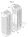
- Fig. 2 is a perspective drawing of the heat exchanger seen from the back side.
- the refrigerant distribution parts 11 comprise superimposed substantially rectangular plates 13 and 14, which have been drawing processed, layered and brazed at the periphery and center thereof.
- the refrigerant distribution parts 11 independent refrigerant paths R1 and R2 through which the refrigerant flows are provided next to each other.
- the refrigerant entrance 15a of the refrigerant path R1 and the refrigerant exit 16b of the refrigerant path R2 are provided next to each other.
- the refrigerant exit 15b of the refrigerant path R1 and the refrigerant entrance 16a of the refrigerant path R2 are provided next to each other.
- the plates 13 and 14 that form the refrigerant paths R1 and R2 are recessed from the outside to form a plurality of dimples 17, and a plurality of bulge parts 18 are formed in the refrigerant paths R1 and R2 by these dimples 17.
- inner fins can be sandwiched between the plates 13 and 14 to form the refrigerant paths R1 and R2 as well.
- the refrigerant entrance 15a comprises openings 13-1a and 14-1a formed respectively in the plates 13 and 14, and as shown in Fig. 4, the refrigerant entrances 15a provided on each of the refrigerant distribution parts 11 form a continuous space Sin 1 (the refrigerant circulation space) on the entrance side by the fact that the refrigerant fins 12 are shorter than the plates 13 and 14.
- the refrigerant exit 15b comprises openings 13-1b and 14-1b formed in the plates 13 and 14, and as shown in Fig. 5, the refrigerant exit 15b provided on each of the refrigerant distribution parts 11 forms a continuous space Sout 1 (refrigerant circulation space) on the exit side by the fact that the refrigerant fins 12 are shorter than the plates 13 and 14.
- the refrigerant entrance 16a comprises the openings 13-2a and 14-2a formed in the plates 13 and 14 and forms the space Sin 2 (the refrigerant circulation space) on the entrance side
- the refrigerant exit 16b comprises the openings 13-2b and 14-2b formed in plates 13 and 14, and forms the space Sout 2 (refrigerant circulation space) on the exit side (refer to Fig. 1).
- the space Sin 1 on the entrance side and the space Sout 2 on the exit side are respectively positioned in fluid communication with the space Sout 1 on the exit side and space Sin 2 on the entrance side.
- one end of the space Sout 1 on the exit side and space Sin 2 on the entrance side is closed off, and the other end shown in Fig. 2 is connected by the communicating path 30.
- the refrigerant is distributed in each of the refrigerant distribution parts 11 by the process of progressing through the space Sin 1 on the entrance side in the direction of the arrow shown in the figure, is evaporated by the process of flowing through each of the refrigerant paths R1, and merged in the space Sout 1 on the exit side.
- the refrigerant progresses through the space Sin 2 on the entrance side in the direction opposite to that of the space Sout 1 on the exit side, and by this process, the refrigerant is distributed to each of the refrigerant distribution parts 11, further evaporated by a process of flowing through each of the refrigerant paths R2, and again merges and flows into the space Sout on 2 the exit side.
- the opening 13-1a in the plate 13 that forms the refrigerant entrance 15a is formed smaller than the opening 14-1a of the plate 14 that similarly acts as the refrigerant entrance 15a.
- an opening 14-1a is formed at the same position in each of the refrigerant distribution paths 11, but the openings 13-1a are formed at respectively differing positions in each of the refrigerant distribution parts 11. This means that because the refrigerant distribution part 11 is layered, the part that forms the opening 13-1a provides a function as an baffle plate 20 (a cooling distribution means) that prevents flow of the refrigerant to the opening 14-1a forming the refrigerant entrance 15a.
- the openings 13-1a are provided on the adjacent baffle plate 20 and disposed so as not to overlap completely with their two adjacent openings 13-1a in the direction of flow of the refrigerant.
- the opening 14-2a of the plate 14 forming the refrigerant entrance 16a is structured similarly (refer to Fig. 3). Below, the space Sin 1 on the entrance side will be explained, but the explanation is similar for the space Sin 2 on the entrance side as well.
- the refrigerant that flows through the space Sin 1 on the entrance side flows downstream while passing through the openings 13-1a formed by each of the baffle plates 20, and the part of the refrigerant that cannot pass through the opening 13-1a is guided by the baffle plates 20 to flow into the refrigerant path R1.
- the openings 13-1a are disposed so as not to overlap completely the openings 13-1a of the adjacent baffle plates 20 that are provided, a part of the refrigerant that passes, for example, through the opening 13-1a of the baffle plate 20a on the upstream side cannot pass through the opening 13-1a because the flow is blocked by the baffle plate 20b when flowing through the opening 13-1a of the adjacent baffle plate 20b (refer to fig. 4).
- each baffle plate 20 is not limited to one, but for example, as shown in Fig. 6, may be provided in plurality, and furthermore, the size of each of the openings 13-1a can be respectively formed so as to be different.
- baffle plates 20 can also be provided on the plate 14 side.
- baffle plates 20 do not need to be formed on all of the plates 13 (14), and only need to be provided on at least one of plates 13 or 14 among the spaces Sin 1 and Sin 2 on the entrance side.
- each opening 13-1a is formed larger than the corresponding opening 13-1a of the baffle plate 20 (21) positioned in the direction of flow of the refrigerant.
- all the part of the refrigerant that passes through the opening 13-1a of the baffle plate 20a (21a) on the upstream side cannot pass through the opening 13-1a of the baffle plate 20b (21b) because a part of the flow is deflected toward a refrigerant path R1 by the baffle plate 21b when passing through the opening 13-1a of the adjacent baffle plate 21b in the downstream direction.
- the refrigerant can be distributed uniformly by all of the refrigerant distribution parts 11 which are provided in plurality.
- the openings 13-1a of the baffle plates 21 are furthermore concentrically aligned.
- the refrigerant flows through one side of the two refrigerant paths R1 and R2, and thus heating due to the stagnation of the refrigerant is prevented.
- the refrigerant can be distributed more evenly in the refrigerant distribution part 11 because the refrigerant is distributed by the baffle plates 20 (21).
- the space Sout 1 on the exit side and space Sin 2 on the entrance side can be connected by the communicating path 30'.
- the refrigerant can be distributed more evenly.
Landscapes
- Engineering & Computer Science (AREA)
- Physics & Mathematics (AREA)
- Thermal Sciences (AREA)
- Mechanical Engineering (AREA)
- General Engineering & Computer Science (AREA)
- Heat-Exchange Devices With Radiators And Conduit Assemblies (AREA)
- Details Of Heat-Exchange And Heat-Transfer (AREA)
Applications Claiming Priority (2)
| Application Number | Priority Date | Filing Date | Title |
|---|---|---|---|
| JP2000318443A JP2002130985A (ja) | 2000-10-18 | 2000-10-18 | 熱交換器 |
| JP2000318443 | 2000-10-18 |
Publications (3)
| Publication Number | Publication Date |
|---|---|
| EP1199535A2 true EP1199535A2 (de) | 2002-04-24 |
| EP1199535A3 EP1199535A3 (de) | 2002-07-10 |
| EP1199535B1 EP1199535B1 (de) | 2004-01-07 |
Family
ID=18797070
Family Applications (1)
| Application Number | Title | Priority Date | Filing Date |
|---|---|---|---|
| EP01402676A Expired - Lifetime EP1199535B1 (de) | 2000-10-18 | 2001-10-17 | Wärmetauscher |
Country Status (4)
| Country | Link |
|---|---|
| US (1) | US7021371B2 (de) |
| EP (1) | EP1199535B1 (de) |
| JP (1) | JP2002130985A (de) |
| DE (1) | DE60101714T2 (de) |
Cited By (1)
| Publication number | Priority date | Publication date | Assignee | Title |
|---|---|---|---|---|
| CN100347500C (zh) * | 2004-09-15 | 2007-11-07 | 三星电子株式会社 | 使用微通道管的蒸发器 |
Families Citing this family (31)
| Publication number | Priority date | Publication date | Assignee | Title |
|---|---|---|---|---|
| DE10214467A1 (de) * | 2002-03-30 | 2003-10-09 | Modine Mfg Co | Abgaswärmetauscher für Kraftfahrzeuge |
| KR100687637B1 (ko) * | 2002-07-11 | 2007-02-27 | 한라공조주식회사 | 열교환기 |
| US6822850B2 (en) * | 2002-09-27 | 2004-11-23 | Rockwell Automation Technologies, Inc. | Laminated bus bar for use with a power conversion configuration |
| US6721181B1 (en) | 2002-09-27 | 2004-04-13 | Rockwell Automation Technologies, Inc. | Elongated heat sink for use in converter assemblies |
| US6885553B2 (en) * | 2002-09-27 | 2005-04-26 | Rockwell Automation Technologies, Inc. | Bus bar assembly for use with a compact power conversion assembly |
| US6956742B2 (en) * | 2002-09-27 | 2005-10-18 | Rockwell Automation Technologies, Inc. | Compact liquid converter assembly |
| US7068507B2 (en) | 2002-09-27 | 2006-06-27 | Rockwell Automation Technologies, Inc. | Compact liquid converter assembly |
| KR100917171B1 (ko) | 2003-01-15 | 2009-09-21 | 한라공조주식회사 | 열교환기 |
| JP4124136B2 (ja) * | 2003-04-21 | 2008-07-23 | 株式会社デンソー | 冷媒蒸発器 |
| JP2005241170A (ja) * | 2004-02-27 | 2005-09-08 | Mitsubishi Heavy Ind Ltd | 熱交換器 |
| US7377126B2 (en) | 2004-07-14 | 2008-05-27 | Carrier Corporation | Refrigeration system |
| WO2006028296A1 (en) * | 2004-09-10 | 2006-03-16 | Showa Denko K.K. | Laminated heat exchanger |
| US20060101850A1 (en) * | 2004-11-12 | 2006-05-18 | Carrier Corporation | Parallel flow evaporator with shaped manifolds |
| US7806171B2 (en) * | 2004-11-12 | 2010-10-05 | Carrier Corporation | Parallel flow evaporator with spiral inlet manifold |
| US7398819B2 (en) | 2004-11-12 | 2008-07-15 | Carrier Corporation | Minichannel heat exchanger with restrictive inserts |
| US20060137368A1 (en) * | 2004-12-27 | 2006-06-29 | Carrier Corporation | Visual display of temperature differences for refrigerant charge indication |
| US7523781B2 (en) * | 2005-01-24 | 2009-04-28 | Halls Climate Control Corporation | Heat exchanger |
| CA2596331A1 (en) * | 2005-02-02 | 2006-08-10 | Carrier Corporation | Liquid-vapor separator for a minichannel heat exchanger |
| WO2006083426A1 (en) * | 2005-02-02 | 2006-08-10 | Carrier Corporation | Tube inset and bi-flow arrangement for a header of a heat pump |
| US8683690B2 (en) * | 2006-01-19 | 2014-04-01 | Modine Manufacturing Company | Flat tube, flat tube heat exchanger, and method of manufacturing same |
| EP2293003A2 (de) * | 2006-01-19 | 2011-03-09 | Modine Manufacturing Company | Flachrohr für Wärmetauscher und sein Fertigungsverfahren |
| CN201059823Y (zh) * | 2007-06-19 | 2008-05-14 | 上海双桦汽车零部件股份有限公司 | 平行流蒸发器 |
| JP2010048536A (ja) * | 2008-08-25 | 2010-03-04 | Denso Corp | 熱交換器 |
| JP2012052715A (ja) * | 2010-08-31 | 2012-03-15 | Mitsubishi Heavy Ind Ltd | 熱交換器 |
| US10767937B2 (en) | 2011-10-19 | 2020-09-08 | Carrier Corporation | Flattened tube finned heat exchanger and fabrication method |
| CA2955854A1 (en) | 2014-07-21 | 2016-01-28 | Dana Canada Corporation | Heat exchanger with flow obstructions to reduce fluid dead zones |
| US20170219302A1 (en) * | 2014-07-29 | 2017-08-03 | Kyocera Corporation | Heat exchanger |
| KR101931971B1 (ko) * | 2016-02-05 | 2018-12-24 | 주식회사 경동나비엔 | 열교환기 |
| KR101784367B1 (ko) * | 2016-02-05 | 2017-10-11 | 주식회사 경동나비엔 | 열교환기 |
| KR101784368B1 (ko) * | 2016-02-05 | 2017-10-11 | 주식회사 경동나비엔 | 열교환기 |
| DE102019215392A1 (de) * | 2019-10-08 | 2021-04-08 | Mahle International Gmbh | Stapelscheibenwärmetauscher |
Family Cites Families (20)
| Publication number | Priority date | Publication date | Assignee | Title |
|---|---|---|---|---|
| US4153106A (en) * | 1976-03-09 | 1979-05-08 | Nihon Radiator Co., Ltd. (Nihon Rajieeta Kabushiki Kaisha) | Parallel flow type evaporator |
| US4621685A (en) * | 1983-09-12 | 1986-11-11 | Diesel Kiki Co., Ltd. | Heat exchanger comprising condensed moisture drainage means |
| JPS6380169A (ja) * | 1986-09-24 | 1988-04-11 | カルソニックカンセイ株式会社 | 膨張弁付積層型エバポレ−タ |
| JP2584060B2 (ja) * | 1989-06-28 | 1997-02-19 | 松下冷機株式会社 | 積層型熱交換器 |
| FR2691242B1 (fr) * | 1992-05-13 | 1994-07-08 | Valeo Thermique Moteur Sa | Boite a eau a vase d'expansion integre pour echangeur de chaleur, en particulier pour vehicule automobile. |
| CA2166395C (en) * | 1993-07-03 | 2006-05-09 | Josef Osthues | Plate heat exchanger with a refrigerant distributor |
| JPH08189725A (ja) * | 1995-01-05 | 1996-07-23 | Nippondenso Co Ltd | 冷媒蒸発器 |
| JP3172859B2 (ja) * | 1995-02-16 | 2001-06-04 | 株式会社ゼクセルヴァレオクライメートコントロール | 積層型熱交換器 |
| JP3632248B2 (ja) | 1995-07-21 | 2005-03-23 | 株式会社デンソー | 冷媒蒸発器 |
| JP3866797B2 (ja) * | 1995-10-20 | 2007-01-10 | 株式会社デンソー | 冷媒蒸発器 |
| JP3719453B2 (ja) * | 1995-12-20 | 2005-11-24 | 株式会社デンソー | 冷媒蒸発器 |
| JP3666091B2 (ja) * | 1995-12-22 | 2005-06-29 | 株式会社デンソー | 冷媒蒸発器 |
| US5979544A (en) * | 1996-10-03 | 1999-11-09 | Zexel Corporation | Laminated heat exchanger |
| JPH10325645A (ja) * | 1997-05-26 | 1998-12-08 | Denso Corp | 冷媒蒸発器 |
| JPH10325646A (ja) * | 1997-05-27 | 1998-12-08 | Mitsubishi Heavy Ind Ltd | 熱交換器 |
| US6179051B1 (en) * | 1997-12-24 | 2001-01-30 | Delaware Capital Formation, Inc. | Distributor for plate heat exchangers |
| JP4175443B2 (ja) * | 1999-05-31 | 2008-11-05 | 三菱重工業株式会社 | 熱交換器 |
| JP2001021287A (ja) * | 1999-07-08 | 2001-01-26 | Zexel Valeo Climate Control Corp | 熱交換器 |
| US6318455B1 (en) * | 1999-07-14 | 2001-11-20 | Mitsubishi Heavy Industries, Ltd. | Heat exchanger |
| JP2001201286A (ja) * | 2000-01-21 | 2001-07-27 | Mitsubishi Heavy Ind Ltd | 熱交換チューブ |
-
2000
- 2000-10-18 JP JP2000318443A patent/JP2002130985A/ja not_active Withdrawn
-
2001
- 2001-10-16 US US09/977,426 patent/US7021371B2/en not_active Expired - Fee Related
- 2001-10-17 EP EP01402676A patent/EP1199535B1/de not_active Expired - Lifetime
- 2001-10-17 DE DE60101714T patent/DE60101714T2/de not_active Expired - Lifetime
Cited By (1)
| Publication number | Priority date | Publication date | Assignee | Title |
|---|---|---|---|---|
| CN100347500C (zh) * | 2004-09-15 | 2007-11-07 | 三星电子株式会社 | 使用微通道管的蒸发器 |
Also Published As
| Publication number | Publication date |
|---|---|
| JP2002130985A (ja) | 2002-05-09 |
| US20020043361A1 (en) | 2002-04-18 |
| EP1199535A3 (de) | 2002-07-10 |
| DE60101714T2 (de) | 2004-12-02 |
| US7021371B2 (en) | 2006-04-04 |
| DE60101714D1 (de) | 2004-02-12 |
| EP1199535B1 (de) | 2004-01-07 |
Similar Documents
| Publication | Publication Date | Title |
|---|---|---|
| EP1199535B1 (de) | Wärmetauscher | |
| US6530423B2 (en) | Heat exchanger | |
| JP3960233B2 (ja) | 熱交換器 | |
| JP3017272B2 (ja) | 熱交換器 | |
| US9366463B2 (en) | Evaporator | |
| JP4233419B2 (ja) | 蒸発器 | |
| US6070428A (en) | Stack type evaporator | |
| US20150053384A1 (en) | Heat exchanger header, heat exchanger having the heat exchanger header, refrigeration cycle apparatus and air-conditioning apparatus | |
| EP3872435B1 (de) | Wärmetauscher | |
| JP2004212041A5 (de) | ||
| US8091617B2 (en) | Heat exchanger | |
| US12422201B2 (en) | Heat exchanger | |
| US20040035564A1 (en) | Stack type heat exhcanger | |
| US20070029075A1 (en) | Hybrid evaporator | |
| JP4056663B2 (ja) | 積層型熱交換器 | |
| JP2737286B2 (ja) | 積層型熱交換器 | |
| JP4547205B2 (ja) | 蒸発器 | |
| JP2694738B2 (ja) | 積層型熱交換器 | |
| JP5832642B2 (ja) | 熱交換器用ヘッダ、この熱交換器用ヘッダを備えた熱交換器、冷凍サイクル装置及び空気調和機 | |
| US7059395B2 (en) | Performance heat exchanger, in particular an evaporator | |
| JP2017203609A (ja) | エバポレータ | |
| CA2358890C (en) | Heat exchanger with flow distributing orifice partitions | |
| KR100531016B1 (ko) | 냉매유동성을 향상시킬 수 있는 열교환기용 매니폴드 플레이트및 이를 이용한 열교환기 | |
| JPH10111044A (ja) | 積層型熱交換器 | |
| JP2646473B2 (ja) | 積層型熱交換器 |
Legal Events
| Date | Code | Title | Description |
|---|---|---|---|
| PUAI | Public reference made under article 153(3) epc to a published international application that has entered the european phase |
Free format text: ORIGINAL CODE: 0009012 |
|
| AK | Designated contracting states |
Kind code of ref document: A2 Designated state(s): AT BE CH CY DE DK ES FI FR GB GR IE IT LI LU MC NL PT SE TR |
|
| AX | Request for extension of the european patent |
Free format text: AL;LT;LV;MK;RO;SI |
|
| PUAL | Search report despatched |
Free format text: ORIGINAL CODE: 0009013 |
|
| AK | Designated contracting states |
Kind code of ref document: A3 Designated state(s): AT BE CH CY DE DK ES FI FR GB GR IE IT LI LU MC NL PT SE TR |
|
| AX | Request for extension of the european patent |
Free format text: AL;LT;LV;MK;RO;SI |
|
| 17P | Request for examination filed |
Effective date: 20020813 |
|
| 17Q | First examination report despatched |
Effective date: 20020927 |
|
| GRAH | Despatch of communication of intention to grant a patent |
Free format text: ORIGINAL CODE: EPIDOS IGRA |
|
| AKX | Designation fees paid |
Designated state(s): DE FR |
|
| GRAS | Grant fee paid |
Free format text: ORIGINAL CODE: EPIDOSNIGR3 |
|
| GRAA | (expected) grant |
Free format text: ORIGINAL CODE: 0009210 |
|
| AK | Designated contracting states |
Kind code of ref document: B1 Designated state(s): DE FR |
|
| PG25 | Lapsed in a contracting state [announced via postgrant information from national office to epo] |
Ref country code: FR Free format text: LAPSE BECAUSE OF FAILURE TO SUBMIT A TRANSLATION OF THE DESCRIPTION OR TO PAY THE FEE WITHIN THE PRESCRIBED TIME-LIMIT Effective date: 20040107 |
|
| REG | Reference to a national code |
Ref country code: IE Ref legal event code: FG4D |
|
| REF | Corresponds to: |
Ref document number: 60101714 Country of ref document: DE Date of ref document: 20040212 Kind code of ref document: P |
|
| PLBE | No opposition filed within time limit |
Free format text: ORIGINAL CODE: 0009261 |
|
| STAA | Information on the status of an ep patent application or granted ep patent |
Free format text: STATUS: NO OPPOSITION FILED WITHIN TIME LIMIT |
|
| 26N | No opposition filed |
Effective date: 20041008 |
|
| EN | Fr: translation not filed | ||
| PGFP | Annual fee paid to national office [announced via postgrant information from national office to epo] |
Ref country code: DE Payment date: 20121010 Year of fee payment: 12 |
|
| REG | Reference to a national code |
Ref country code: DE Ref legal event code: R119 Ref document number: 60101714 Country of ref document: DE Effective date: 20140501 |
|
| PG25 | Lapsed in a contracting state [announced via postgrant information from national office to epo] |
Ref country code: DE Free format text: LAPSE BECAUSE OF NON-PAYMENT OF DUE FEES Effective date: 20140501 |