EP1193846A1 - Structure of rotors in stepping motors - Google Patents
Structure of rotors in stepping motors Download PDFInfo
- Publication number
- EP1193846A1 EP1193846A1 EP01810941A EP01810941A EP1193846A1 EP 1193846 A1 EP1193846 A1 EP 1193846A1 EP 01810941 A EP01810941 A EP 01810941A EP 01810941 A EP01810941 A EP 01810941A EP 1193846 A1 EP1193846 A1 EP 1193846A1
- Authority
- EP
- European Patent Office
- Prior art keywords
- magnetic component
- rotor
- portions
- magnetic
- stepping motor
- Prior art date
- Legal status (The legal status is an assumption and is not a legal conclusion. Google has not performed a legal analysis and makes no representation as to the accuracy of the status listed.)
- Withdrawn
Links
Images


Classifications
-
- H—ELECTRICITY
- H02—GENERATION; CONVERSION OR DISTRIBUTION OF ELECTRIC POWER
- H02K—DYNAMO-ELECTRIC MACHINES
- H02K37/00—Motors with rotor rotating step by step and without interrupter or commutator driven by the rotor, e.g. stepping motors
- H02K37/10—Motors with rotor rotating step by step and without interrupter or commutator driven by the rotor, e.g. stepping motors of permanent magnet type
- H02K37/12—Motors with rotor rotating step by step and without interrupter or commutator driven by the rotor, e.g. stepping motors of permanent magnet type with stationary armatures and rotating magnets
- H02K37/14—Motors with rotor rotating step by step and without interrupter or commutator driven by the rotor, e.g. stepping motors of permanent magnet type with stationary armatures and rotating magnets with magnets rotating within the armatures
- H02K37/18—Motors with rotor rotating step by step and without interrupter or commutator driven by the rotor, e.g. stepping motors of permanent magnet type with stationary armatures and rotating magnets with magnets rotating within the armatures of homopolar type
Definitions
- the present invention relates to a structure of a rotor in a stepping motor, widely used for paper-feeders in facsimiles and scanners in copying machines.
- An example of prior art is a stepping motor having a rotor comprising a permanent magnet between two rotating components that are held by the rotor axis at an appropriate spacing, and one of the rotating component is magnetized as N-pole and the other as S-pole (see Fig. 4 in Japanese Patent Laid-open No. Hei 10-80124), or stepping motors having a rotor comprising a cylindrical permanent magnet with multi-polar magnetic parts arranged around the circumference thereof (see Figs. 1 and 2 in the above-mentioned Japanese Patent), or a configuration as shown in Figs.14A and 14B.
- the stepping motor shown in Fig.14A has a stator yoke 42 in a housing 41, and enables a rotor 44 to rotate by bearings 43a and 43b.
- the stator yoke is wound by a coil 46 connected with lead wire 45 to an electric circuit (not shown).
- the rotor 44 includes a rotor axis 47, rotor components 48a and 48b where a plurality of thin steel plates shaped as an approximate gear are stacked at a predetermined spacing and fixed on the rotor axis 47, and magnet 49, as shown in Figs. 14A and 14B.
- one of the prior art for example, (as disclosed in Fig. 4 of the above-mentioned Japanese Patent), wherein a permanent magnet is provided between two rotor components, is apt to make undesired vibration and/or noises because such a structure has magnetic salient portions (teeth) on the circumferential portion.
- the vibration and noises are also problems found in a prior art shown in Figs. 14A and 14B.
- the stepping motor having a rotor provided with a cylindrical permanent magnet with multi-polar magnetic parts arranged around the circumferential surface thereof (disclosed in Figs. 1 and 2 of the above-mentioned Japanese Patent), this prior art is designed to eliminate vibration and noise problems.
- the present invention is to provide a structure of a rotor in stepping motors capable of not only rotating much faster, but also eliminating undesired vibration and noises even under rotation at high speed.
- Another object of the present invention is to provide the structure of rotor capable of performing with two-phase type, and in addition, a simpler and more cost-effective motor manufacturing equipment can be built.
- a structure of a rotor in a stepping motor having a rotor comprising magnetic component whose circumferential part is magnetized in multipole along the circumferential surface thereof, the stepping motor being capable of forcing the rotor to rotate by magnetic force provided between magnetic poles of the rotor and excited salient poles of a stator, characterized in that the magnetic component comprises two magnetic component portions each shaped as an approximate ring, and the two magnetic component portions are either combined with each other or set up separately at appropriate spacing inbetween.
- the two magnetic component portions have a plurality of N-poles and a plurality of S-poles, said N-poles and S-poles each being magnetized alternately at appropriate spacing inbetween, and the N-poles and S-poles are arranged such that contrary poles face each other.
- the convex portions are radially magnetized so that the convex portions on one magnetic component portion have the contrary pole to the convex portions on the other magnetic component portion, and said convex portions are so arranged that they are in aligned viewed in the axial direction.
- the two magnetic component portions are magnetized with poles contrary to each other, and the two magnetic component portions have convex portions opposing to concave portions when viewed in the axial direction.
- a first embodiment of the present invention is described as follows.
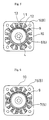
- a stepping motor referred to as the first embodiment of the present invention has a stator 3 equipped in a housing 20, and enables a rotor 2 to rotate around a bearing 21 as shown in Fig. 1, and the rotor 2 comprises mainly a rotor axis 4 capable of rotating freely as being held by the bearing 21, and a magnetic component 5 that held by the rotor 4 by means of supporting portions (not shown) as shown in Fig. 2.
- the magnetic component 5 comprises magnetic component portions 6 and 7 each shaped as an approximate ring. With regard to the magnetic component portions 6 and 7, it is possible that they are so fabricated that both of them are either combined firmly with each other in the axial direction as shown in Fig. 2A, or arranged separately at an appropriate vacant spacing inbetween in the axial direction as shown in Fig. 2B. For the convenience, hereinafter with regard to the magnetic component portions 6 and 7, the portion located at the left hand in Figs. 2A and 2B is called a first magnetic component portion 6 and the other one at the right hand a second magnetic component portion 7.
- N-poles and S-poles are arranged and magnetized alternately.
- the first and second magnetic component portions 6 and 7 are either combined with each other in the axial direction, or disposed at a predetermined spacing E, and before and after that arrangement the magnetic component portions are magnetized.
- the N-poles and S-poles of the first and second magnetic component portions 6 and 7 are arranged so that contrary poles face each other.
- an N-pole of the first magnetic component portion 6 is juxtaposed next to an S-pole of the second component portion 7 when viewed from the viewing angle along the axis 4 of the rotor.
- the stator 3 comprises an approximate-rectangular stator yoke 8 having a hole (whose reference numeral is omitted) at its central part, through which the rotor 2 is inserted, and a coil 9 is wound around the stator yoke 8.
- the coil 9 is connected with lead wire 22 to an electric circuit (not shown).
- the stator yoke 8 comprises a laminated sheet made of a plurality of thin steel plates.
- a magnetic salient portion 12 is provided at the top of each leg 11 of the core located inside the stator yoke 8, and the magnetic salient portion 12 is facing towards the coil 9.
- a plurality of tooth 13 are formed on the circumferential surface of the magnetic salient portion 12 around the circular surface of the magnet salient portion 12.
- a gap (whose reference numeral is omitted) is formed between the teeth 13 and the rotor 2.
- stator 3 can be comprised of first and second stator yoke components 14 and 15 capable of being incorporated in, respectively (see Fig. 4 concerning a second embodiment of the present invention described herein later), and the first and second stator yoke components are so arranged that the two yoke components are displaced with angle of either 90° or 180° with each other.
- the coils 9 are provided correspondingly for the first and second magnetic component portions 6 and 7, and capable of producing magnetic force (both attractive and repulsive) between the coil 9 and the first magnetic component portion 6, and also between the coil 9 and the second magnetic component portion 7.
- the first and second magnetic component portions 6 and 7 are so arranged that contrary poles oppose each other in terms of their physical structure
- the magnetic component 5 of the rotor 2 described beforehand in the first embodiment takes a ring formation so that the distribution curve of the magnetic flux density in the magnetic field is of sine wave.
- the motor gives less vibration and noises than that have teeth on the circumferential surface of the rotor, and furthermore it has smaller inertia and thus able to perform with much faster response.
- the magnetic component 5 is composed of the combination of the first and second magnetic component portions 6 and 7 (see Fig. 2A), each portion is able to receive magnetic force independently, thus resulting in good controllability of the motor as applied with two-phase type.
- the magnetic component 5 comprises first and second magnetic component portions 6 and 7, a preferable magnetizing apparatus can be designed on the basis of the first and second magnetic component portions 6 and 7, thus the magnetizing apparatus should be smaller and hence the entire manufacturing equipment can be made smaller than before.
- the stator yoke 8 of the stator 3 is composed of two stator yoke components 14 and 15, which can be combined with each other.
- the portion located at the left hand in Fig. 4A is called a first stator yoke component 14 and the other one at the right hand a second stator yoke component 14.
- the first and second stator yoke components 14 and 15 comprise a laminated sheet made of plural thin steel plates in the same size.
- first and second stator yoke components 14 and 15 are so arranged that the two components are arranged in aberrant position displaced each other by angle of either 90° or 180°, and with regard to the first and second magnetic component portions 6 and 7, they are arranged so that contrary poles oppose each other in terms of physical structure, this type of stepping motor proves itself to be more controllable with two-phase type, just as described in the first embodiment of the present invention.
- this type of stepping motor according to the present invention is capable of preventing undesired vibration and noises, rotating with faster speed, being more controllable with two-phase type, making the manufacturing equipment smaller, and thus reducing the manufacturing cost.
- the steel plates can be prepared with only one type of die, because the first and second stator yoke component portions 14 and 15 are made of a plurality of thin steel plates in the same size, thus the manufacturing equipment can be simpler.
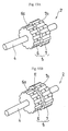
- each shape of the first and second magnetic component portions 6 and 7 is of a ring, however, instead of ring shape, an approximate gear shape is also applicable for the first and second magnetic component portions 6 and 7 as shown in Fig. 7 (as a third embodiment) or Fig. 8 (as a fourth embodiment).
- the first and second magnetic component portions 6 and 7 can be either combined with each other in the axial direction as shown in Fig. 7A, or arranged at an appropriate vacant spacing in-between in the axial direction as shown in Fig. 7B.
- Such the construction principle is also applied for the fourth embodiment of the present invention (see Figs. 8A and 8B) in the same manner, and corresponding constructions are shown in Figs. 8A and 8B, respectively.
- This concept of the constructions is the same in the fifth (see Figs. 10A and 10B) and the sixth (see Figs. 13A and 13B) embodiments of the present invention, and each corresponding construction is shown separately in Figs. 9, 11 and 13.
- the first and second magnetic component portions 6 and 7 have convex portions 6a and 7a, having a lengthy rectangular physique, formed in the axial direction at appropriate spacing being like an approximate gear on the circumferential surface of each portion as shown in Figs. 7A and 7B.
- the convex portion 6a of the first magnetic component portion 6 and the convex portion 7a of the magnetic component portion 7 are magnetized in the radial direction, so that contrary poles face each other when viewed in the axial direction.
- the convex portion 6a of the first magnetic component portion 6 is magnetized as N-pole
- the convex portion 7a of the magnetic component portion 7 as S-pole.
- the first and second magnetic component portions 6 and 7 are combined or disposed at a predetermined spacing E in the axial direction, and the convex portions 6a and 7a are arranged so that a convex portion opposes a concave portion.
- the convex portion 6a (N-pole) of the first magnetic component portion 6 is juxtaposed next to a reentrant (concave) portion (whose reference numeral is omitted) between two convex portions 7a (S-pole) of the second magnetic component portion 7, and the first and second magnetic component portions are combined in the axial direction (Fig. 7A), or disposed at a predetermined spacing E (Fig. 7B).
- the third embodiment of the present invention is capable of doing a fine control over the motor performance with two-phase type, and also constructing of a smaller manufacturing equipment is possible by the same reason for the first and second embodiments of the present invention.
- circular reentrant (concave) portions 16 are formed at either side of the combined portion of the first and second magnetic component portions, as shown in Figs. 8A and 8B.
- the fourth embodiment of the present invention is capable of rotating much faster than the third embodiment because now that it is lighter as the circular reentrant (concave) portion 16 is formed at either side of the combined portion of the first and second magnetic component portions.
- the convex portions 6a and 7a on the first and second magnetic component portions 6 and 7 are formed in positions, and either combined or disposed at a predetermined spacing E, however, it is also possible that the convex portions 6a and 7a are aligned in series (more specifically, the convex portion 6a (N-pole) of the magnetic component portion 6 is aligned with convex portion 7a (S-pole) of the magnetic component portion 7 in series in the axial direction), and both magnetic component portions are either combined each other or disposed at a predetermined spacing E.
- the fifth embodiment of the present invention is capable of doing a fine control over the motor performance with. two-phase type, and also constructing a smaller manufacturing equipment is possible.
- the sixth embodiment of the present invention is capable of rotating much faster than before because now that it is lighter as the circular reentrant (concave) portion 16 is introduced into either side of the combined portion of the first and second magnetic component portions 6 and 7.
- the rotors are exemplified wherein the diameter of the first magnetic component portion 6 which includes the convex portion 6a is the same as that of the second magnetic component 7 which includes the convex portion 7a, however, instead it is possible that the diameter of the first magnetic component portion 6 is different from that of the second magnetic component portion 7 (a seventh embodiment of the present invention).
- the magnetic component comprises two magnetic component portions magnetized in multipole on their circumferential surfaces, being either combined with each other or disposed at a predetermined spacing, and shaped as an approximate ring.
- the distribution curve of magnetic flux in the magnetic field is of sine wave, which means that this type of stepping motor prevents undesired vibration and noises more than other types that have teeth on the circumferential surfaces of their rotors.
- the type of stepping motor according to the present invention has a smaller inertia and faster-response ability because the magnetic component in the rotor is ring-like.
- the magnetic component comprises two magnetic component portions being either combined with each other or arranged at an appropriate spacing, and the respective portions are capable of receiving magnetic force independently, thus resulting in better performance with regard to controllability with the two-phase type.
- the magnetizing apparatus can be smaller on the basis of the physical size of the two magnetic component portions, because the magnetic component comprises two magnetic component portions, thus constructing a smaller sized manufacturing equipment is possible.
- the magnetic component comprises two magnetic component portions being either combined with each other or arranged at an appropriate spacing, and the respective portions are capable of receiving magnetic force independently, thereby resulting in better performance with regard to controllability with the two-phase type.
- the magnetizing apparatus can be smaller on the basis of the physical size of thc two magnetic component portions, because the magnetic component comprises two magnetic component portions. Thus, it is possible to construct a smaller sized manufacturing equipment.
Landscapes
- Engineering & Computer Science (AREA)
- Power Engineering (AREA)
- Iron Core Of Rotating Electric Machines (AREA)
- Permanent Field Magnets Of Synchronous Machinery (AREA)
Applications Claiming Priority (2)
| Application Number | Priority Date | Filing Date | Title |
|---|---|---|---|
| JP2000296600A JP2002112521A (ja) | 2000-09-28 | 2000-09-28 | ステップモータのロータ構造 |
| JP2000296600 | 2000-09-28 |
Publications (1)
| Publication Number | Publication Date |
|---|---|
| EP1193846A1 true EP1193846A1 (en) | 2002-04-03 |
Family
ID=18778853
Family Applications (1)
| Application Number | Title | Priority Date | Filing Date |
|---|---|---|---|
| EP01810941A Withdrawn EP1193846A1 (en) | 2000-09-28 | 2001-09-27 | Structure of rotors in stepping motors |
Country Status (3)
| Country | Link |
|---|---|
| US (2) | US20020036437A1 (hr) |
| EP (1) | EP1193846A1 (hr) |
| JP (1) | JP2002112521A (hr) |
Cited By (1)
| Publication number | Priority date | Publication date | Assignee | Title |
|---|---|---|---|---|
| EP1672771A3 (en) * | 2004-12-15 | 2009-07-08 | Sanyo Denki Co., Ltd. | Rotor for hybrid type stepping motor and manufacturing method thereof |
Families Citing this family (8)
| Publication number | Priority date | Publication date | Assignee | Title |
|---|---|---|---|---|
| US7183675B2 (en) | 2002-04-26 | 2007-02-27 | Delta Electronics, Inc. | Permanent magnet stepping motor |
| TW595835U (en) * | 2002-04-26 | 2004-06-21 | Delta Electronics Inc | Rotor structure of permanent-magnet step motor |
| US7402932B2 (en) * | 2005-01-31 | 2008-07-22 | Applegate Rodney W | Apparatus and system for driving a fan using a linear induction motor |
| JP2007043763A (ja) * | 2005-07-29 | 2007-02-15 | Nidec Sankyo Corp | ロータマグネットの製造方法、およびモータ |
| JP2009136089A (ja) * | 2007-11-30 | 2009-06-18 | Mitsumi Electric Co Ltd | ステッピングモータ用ロータ及びステッピングモータ |
| JP2013009560A (ja) * | 2011-06-27 | 2013-01-10 | Minebea Co Ltd | ハイブリッド型ステッピングモータ |
| CN104319060B (zh) * | 2014-09-17 | 2016-08-24 | 徐州通用高新磁电有限公司 | 一种永磁转子正弦充磁方法和装置 |
| JP7415487B2 (ja) * | 2019-11-28 | 2024-01-17 | セイコーエプソン株式会社 | アキシャルギャップモーター |
Citations (12)
| Publication number | Priority date | Publication date | Assignee | Title |
|---|---|---|---|---|
| US3293460A (en) * | 1960-02-22 | 1966-12-20 | Fujitsu Ltd | Electric stepping motor with a nonmagnetic spacer between adjacent rotor sections |
| US3671841A (en) * | 1970-05-01 | 1972-06-20 | Tri Tech | Stepper motor with stator biasing magnets |
| US3801842A (en) * | 1972-06-27 | 1974-04-02 | Ncr | Stepping motor |
| US4406958A (en) * | 1981-04-06 | 1983-09-27 | The Superior Electric Company | Stepping motors with disc magnet |
| US4528473A (en) * | 1983-02-26 | 1985-07-09 | Shinano Kenshi Kabushiki Kaisha | Permanent magnet type step motor |
| JPS60241759A (ja) * | 1984-05-14 | 1985-11-30 | Matsushita Electric Works Ltd | 同期電動機 |
| JPS6135152A (ja) * | 1984-07-25 | 1986-02-19 | Matsushita Electric Works Ltd | ステツプ電動機 |
| JPS61150656A (ja) * | 1984-12-25 | 1986-07-09 | Matsushita Electric Ind Co Ltd | ステツプモ−タ |
| JPH01103151A (ja) * | 1987-10-16 | 1989-04-20 | Olympus Optical Co Ltd | ステッピングモータ |
| US5384506A (en) * | 1992-05-29 | 1995-01-24 | Canon Kabushiki Kaisha | Stepper motor |
| JPH08214519A (ja) * | 1995-02-06 | 1996-08-20 | Akira Chiba | 永久磁石を用いた両突極性電動発電機 |
| WO1999019962A1 (en) * | 1997-10-16 | 1999-04-22 | Omnidyne Inc. | Generators and transformers with toroidally wound stator winding |
Family Cites Families (9)
| Publication number | Priority date | Publication date | Assignee | Title |
|---|---|---|---|---|
| USRE25445E (en) * | 1963-09-17 | fredrickson | ||
| DE2337905A1 (de) | 1973-07-26 | 1975-02-13 | Gerhard Berger Fabrikation Ele | Selbstanlaufender synchronmotor mit dauermagnetlaeufer |
| US4009406A (en) | 1975-11-25 | 1977-02-22 | Tokuzo Inariba | Synchronous micromotor with a permanent magnet rotor |
| JPS59204461A (ja) * | 1983-05-09 | 1984-11-19 | Japan Servo Co Ltd | 永久磁石形ステツピングモ−タ |
| JPS6070941A (ja) * | 1983-09-28 | 1985-04-22 | Tokuzo Inariba | 小型電動機用極歯群構造体及びその製造方法 |
| JPS62185481U (hr) * | 1986-05-13 | 1987-11-25 | ||
| JPH1080124A (ja) | 1996-08-30 | 1998-03-24 | Japan Servo Co Ltd | 永久磁石式回転電機 |
| JPH11289737A (ja) * | 1998-04-03 | 1999-10-19 | Oriental Motor Co Ltd | ハイブリッド型ステッピングモータ |
| JP2000324769A (ja) * | 1999-05-13 | 2000-11-24 | Matsushita Electric Ind Co Ltd | ステッピングモータ |
-
2000
- 2000-09-28 JP JP2000296600A patent/JP2002112521A/ja active Pending
-
2001
- 2001-09-25 US US09/960,927 patent/US20020036437A1/en not_active Abandoned
- 2001-09-27 EP EP01810941A patent/EP1193846A1/en not_active Withdrawn
-
2003
- 2003-03-24 US US10/394,159 patent/US6958556B2/en not_active Expired - Lifetime
Patent Citations (12)
| Publication number | Priority date | Publication date | Assignee | Title |
|---|---|---|---|---|
| US3293460A (en) * | 1960-02-22 | 1966-12-20 | Fujitsu Ltd | Electric stepping motor with a nonmagnetic spacer between adjacent rotor sections |
| US3671841A (en) * | 1970-05-01 | 1972-06-20 | Tri Tech | Stepper motor with stator biasing magnets |
| US3801842A (en) * | 1972-06-27 | 1974-04-02 | Ncr | Stepping motor |
| US4406958A (en) * | 1981-04-06 | 1983-09-27 | The Superior Electric Company | Stepping motors with disc magnet |
| US4528473A (en) * | 1983-02-26 | 1985-07-09 | Shinano Kenshi Kabushiki Kaisha | Permanent magnet type step motor |
| JPS60241759A (ja) * | 1984-05-14 | 1985-11-30 | Matsushita Electric Works Ltd | 同期電動機 |
| JPS6135152A (ja) * | 1984-07-25 | 1986-02-19 | Matsushita Electric Works Ltd | ステツプ電動機 |
| JPS61150656A (ja) * | 1984-12-25 | 1986-07-09 | Matsushita Electric Ind Co Ltd | ステツプモ−タ |
| JPH01103151A (ja) * | 1987-10-16 | 1989-04-20 | Olympus Optical Co Ltd | ステッピングモータ |
| US5384506A (en) * | 1992-05-29 | 1995-01-24 | Canon Kabushiki Kaisha | Stepper motor |
| JPH08214519A (ja) * | 1995-02-06 | 1996-08-20 | Akira Chiba | 永久磁石を用いた両突極性電動発電機 |
| WO1999019962A1 (en) * | 1997-10-16 | 1999-04-22 | Omnidyne Inc. | Generators and transformers with toroidally wound stator winding |
Non-Patent Citations (5)
| Title |
|---|
| PATENT ABSTRACTS OF JAPAN vol. 010, no. 104 (E - 397) 19 April 1986 (1986-04-19) * |
| PATENT ABSTRACTS OF JAPAN vol. 010, no. 192 (E - 417) 5 July 1986 (1986-07-05) * |
| PATENT ABSTRACTS OF JAPAN vol. 010, no. 352 (E - 458) 27 November 1986 (1986-11-27) * |
| PATENT ABSTRACTS OF JAPAN vol. 013, no. 344 (E - 797) 3 August 1989 (1989-08-03) * |
| PATENT ABSTRACTS OF JAPAN vol. 1996, no. 12 26 December 1996 (1996-12-26) * |
Cited By (1)
| Publication number | Priority date | Publication date | Assignee | Title |
|---|---|---|---|---|
| EP1672771A3 (en) * | 2004-12-15 | 2009-07-08 | Sanyo Denki Co., Ltd. | Rotor for hybrid type stepping motor and manufacturing method thereof |
Also Published As
| Publication number | Publication date |
|---|---|
| US20030184166A1 (en) | 2003-10-02 |
| US6958556B2 (en) | 2005-10-25 |
| JP2002112521A (ja) | 2002-04-12 |
| US20020036437A1 (en) | 2002-03-28 |
Similar Documents
| Publication | Publication Date | Title |
|---|---|---|
| JP2733824B2 (ja) | 2相式永久磁石回転電機 | |
| US7595575B2 (en) | Motor/generator to reduce cogging torque | |
| US6504272B2 (en) | Multi-phase electric rotating machine having toroidal coils and using method thereof | |
| JP3535012B2 (ja) | ラジアルギャップ型小型円筒型回転電機 | |
| US20050179337A1 (en) | Axial gap electric rotary machine | |
| US20060022553A1 (en) | Rotating electric machine | |
| JPS63257448A (ja) | 電子的に整流されるコレクタのない直流モータ | |
| JP2007104819A (ja) | 回転電機 | |
| JP3928297B2 (ja) | 電動機及びその製造方法 | |
| US6958556B2 (en) | Structure of rotors in stepping motors | |
| JP7193422B2 (ja) | 回転電機及び回転電機の製造方法 | |
| CN103259354B (zh) | 转子和马达 | |
| JP2002136094A (ja) | ステッピングモータ | |
| JPS6264248A (ja) | 薄形dcブラシレスモ−タ | |
| JP3389637B2 (ja) | ステッピングモータ | |
| JP2011072087A (ja) | アキシャルギャップモータ | |
| JP3225072B2 (ja) | 外転式長細形モータ | |
| JP2003284310A (ja) | モータおよびその製造方法 | |
| JP3367752B2 (ja) | リニアパルスモータ | |
| JP3679294B2 (ja) | 環状コイル式回転電機 | |
| JP4760286B2 (ja) | モータ | |
| JP5401753B2 (ja) | 回転電機 | |
| JP3138628B2 (ja) | ハイブリッド型ステップモータの駆動方法 | |
| JP3272297B2 (ja) | ステッピングモータ | |
| JP2005295765A (ja) | 回転電機の電機子 |
Legal Events
| Date | Code | Title | Description |
|---|---|---|---|
| PUAI | Public reference made under article 153(3) epc to a published international application that has entered the european phase |
Free format text: ORIGINAL CODE: 0009012 |
|
| AK | Designated contracting states |
Kind code of ref document: A1 Designated state(s): AT BE CH CY DE DK ES FI FR GB GR IE IT LI LU MC NL PT SE TR Kind code of ref document: A1 Designated state(s): DE FR GB IT |
|
| AX | Request for extension of the european patent |
Free format text: AL;LT;LV;MK;RO;SI |
|
| 17P | Request for examination filed |
Effective date: 20021002 |
|
| AKX | Designation fees paid |
Free format text: DE FR GB IT |
|
| 17Q | First examination report despatched |
Effective date: 20030417 |
|
| STAA | Information on the status of an ep patent application or granted ep patent |
Free format text: STATUS: THE APPLICATION IS DEEMED TO BE WITHDRAWN |
|
| 18D | Application deemed to be withdrawn |
Effective date: 20031028 |