EP1186714A2 - Leitelement für Schutzeinrichtungen - Google Patents
Leitelement für Schutzeinrichtungen Download PDFInfo
- Publication number
- EP1186714A2 EP1186714A2 EP01250314A EP01250314A EP1186714A2 EP 1186714 A2 EP1186714 A2 EP 1186714A2 EP 01250314 A EP01250314 A EP 01250314A EP 01250314 A EP01250314 A EP 01250314A EP 1186714 A2 EP1186714 A2 EP 1186714A2
- Authority
- EP
- European Patent Office
- Prior art keywords
- guide element
- element according
- protective device
- elements
- profile
- Prior art date
- Legal status (The legal status is an assumption and is not a legal conclusion. Google has not performed a legal analysis and makes no representation as to the accuracy of the status listed.)
- Granted
Links
Images



Classifications
-
- E—FIXED CONSTRUCTIONS
- E01—CONSTRUCTION OF ROADS, RAILWAYS, OR BRIDGES
- E01F—ADDITIONAL WORK, SUCH AS EQUIPPING ROADS OR THE CONSTRUCTION OF PLATFORMS, HELICOPTER LANDING STAGES, SIGNS, SNOW FENCES, OR THE LIKE
- E01F15/00—Safety arrangements for slowing, redirecting or stopping errant vehicles, e.g. guard posts or bollards; Arrangements for reducing damage to roadside structures due to vehicular impact
- E01F15/14—Safety arrangements for slowing, redirecting or stopping errant vehicles, e.g. guard posts or bollards; Arrangements for reducing damage to roadside structures due to vehicular impact specially adapted for local protection, e.g. for bridge piers, for traffic islands
- E01F15/141—Safety arrangements for slowing, redirecting or stopping errant vehicles, e.g. guard posts or bollards; Arrangements for reducing damage to roadside structures due to vehicular impact specially adapted for local protection, e.g. for bridge piers, for traffic islands for column or post protection
-
- E—FIXED CONSTRUCTIONS
- E01—CONSTRUCTION OF ROADS, RAILWAYS, OR BRIDGES
- E01F—ADDITIONAL WORK, SUCH AS EQUIPPING ROADS OR THE CONSTRUCTION OF PLATFORMS, HELICOPTER LANDING STAGES, SIGNS, SNOW FENCES, OR THE LIKE
- E01F15/00—Safety arrangements for slowing, redirecting or stopping errant vehicles, e.g. guard posts or bollards; Arrangements for reducing damage to roadside structures due to vehicular impact
- E01F15/02—Continuous barriers extending along roads or between traffic lanes
- E01F15/04—Continuous barriers extending along roads or between traffic lanes essentially made of longitudinal beams or rigid strips supported above ground at spaced points
- E01F15/0453—Rails of materials other than metal or concrete, e.g. wood, plastics; Rails of different materials, e.g. rubber-faced metal profiles, concrete-filled steel tubes
-
- E—FIXED CONSTRUCTIONS
- E01—CONSTRUCTION OF ROADS, RAILWAYS, OR BRIDGES
- E01F—ADDITIONAL WORK, SUCH AS EQUIPPING ROADS OR THE CONSTRUCTION OF PLATFORMS, HELICOPTER LANDING STAGES, SIGNS, SNOW FENCES, OR THE LIKE
- E01F15/00—Safety arrangements for slowing, redirecting or stopping errant vehicles, e.g. guard posts or bollards; Arrangements for reducing damage to roadside structures due to vehicular impact
- E01F15/14—Safety arrangements for slowing, redirecting or stopping errant vehicles, e.g. guard posts or bollards; Arrangements for reducing damage to roadside structures due to vehicular impact specially adapted for local protection, e.g. for bridge piers, for traffic islands
- E01F15/143—Protecting devices located at the ends of barriers
Definitions
- the invention relates to a guide element for protective devices for traffic routes according to the preamble of claim 1 and protective devices with such a guide element.
- the invention is based, an initial and To provide the end piece for a protective device, that the protective effect for impacting vehicles in the Improved start and end area of a protective device.
- this object is achieved by a guide element with the features of claim 1, a protective device with the features of claim 29 and a protective device solved with the features of claim 33.
- a guide element for the start or end area of a protective device provided for traffic routes which is an outer shell has an exterior facing the traffic route Profile tape and an interior facing away from the traffic route Includes ribbon.
- the inner profile band is at least via a fastening area on an anchor in the floor or on other parts of the protective device mountable.
- the inner profile band facing away from the traffic route is included preferably formed stronger than the outer profile band, so that it's most of the not through the deformation area absorbed residual energy from an impact and to the releases anchorages connected to the inner profile band.
- the front profile band can be made thinner and possibly even be made of plastic.
- the attachment area can be the attachment of the Guide element on a post, but also on the attachment natural obstacles or other parts of the protective device serve. The only important thing is that at the fastening area in the event of an impact by a vehicle a counterforce is provided.
- the guide element according to the invention is in contrast to that end piece known from the prior art not in Lowered towards the road, but indicates the height of the adjoining protective device. A disadvantageous ramp effect is thus eliminated.
- the guide element has towards its free end, i.e. the completion of the Protective device increasingly away from the road. Thereby becomes a side-impacting vehicle on the road redirected. There is thus a deflection of the Lane of the vehicle has returned to the lane combined with an energy absorption through the deformation of the guide element.
- the guide element preferably has a substantially longitudinal section drop or banana-shaped outer shell on, in which is the deformation area.
- This shape is easily manufactured by e.g. Bending a single sheet in the form of drops or bananas.
- this form through several possibly prefabricated elements produce, for example a drop or Banana-shaped body attached to a curved guardrail becomes.
- a banana shape is understood to mean a shape in which the inner profile band and the outer profile band are bent, but essentially over long distances have the same distance from each other. This makes possible it, several damping elements of the same size between to arrange the profile strips. Since the damping elements can have the same size is their large-scale Mass production much more interesting than one Shape in which the distance between the profiled strips changes changes.
- the outer shell is in a preferred embodiment executed in several parts, which means the use of different Materials or different thicknesses of a material allowed.
- an inner profile band the stability and have the profile of a common guardrail
- an outer profile band only as a cover for the deformation area works and e.g. formed as a plate-shaped band is.
- the deformation region preferably has one or more Damping elements on, by their deformation during the Impact additional energy is absorbed, so that the Impact is softer.
- the damping elements exist in a preferred embodiment of the invention made of plastic. For example, due to good processability Polypropylene or polyvinyl chloride used. in principle however, any plastics can be used. As well is the design and arrangement of the damping elements any. Preferred arrangements of the damping elements are here a honeycomb or half-timbered structure.
- the design of the damping elements is advantageous as tubular elements with a preferred diameter of 10 up to 30 cm.
- a plastic insulation material for example a plastic foam
- This plastic foam can be arranged alternatively or in addition to the deformable damping elements.
- An energy-absorbing plastic foam for example based on polyolefins, polyurethane or styrene polymers, with a specific energy absorption of at least 1 * 10 -5 , preferably 4 * 10 -5 J / mm 3 and a compression set at 50% compression of less than 50% is preferred. , preferably less than 40%.
- the specific energy consumption is according to EN 826 at a Test speed of 50 mm / min measured, the compression set according to DIN 53 572 at 50% compression 24 hours after Discharge.
- Polypropylene particle foam is particularly preferred with a density of 15 to 150 g / l, preferably from 20 to 100 g / l. This has compared to other plastic foams the advantage of a very high energy absorption, good resilience, excellent media and weather resistance and low water absorption. It is also recyclable, which is an advantage is when the damping elements and possibly also the outer profile band also as a plastic base polypropylene to have.
- a typical polypropylene particle foam is NEOPOLEN P from BASF AG. At a density of 20 g / l it has a spec. Energy consumption of 7.5 * 10 -5 J / mm 3 and at 80 g / l of 50 * 10 -5 J / mm 3 .
- the compression set values range from 27 to 30%.
- plastic is not on the inner area of the guide element limited.
- the side facing the traffic route of the guide element i.e. the outer profile band also Plastic is made.
- hard plastic used to the impacting vehicle to oppose sufficient resistance.
- the one behind it Damping element is preferably made of plastic insulation material.
- the Side of the outer shell facing the traffic route together with prefabricated the damping element as a module. The assembly this makes it much easier on site.
- the guide element faces the traffic route Outside preferably reflectors attached or embedded on which the vehicle drivers get to the start early a protective device.
- Damping element made of metal, with vertically running Damping parts are provided. This leaves a material saving and diverse design too, since also a relative thin-walled design of the damping elements such as is very stable with simple struts.
- the traffic route opposite side of the guide element on which the fastening area for connection to a post or for anchoring is formed in the bottom preferably made of metal, in particular Steel.
- a guide element in which at least two Damping elements designed as tubular elements and immediately on the inside of the traffic route Side of the outer shell spaced apart are.
- the deformation area contains a plastic insulation material that is preferred in Form of plastic foam segments between the inner Profile tape and the outer profile tape is introduced.
- the distance between the inner profile band and the outer Profile tape is largely constant (Banana shape), whereby plastic foam segments are the same Size are arranged between the profile strips. this will thanks to the equidistant spacing of the profile strips. There is also an equidistant distance between the profile strips then makes sense if no additional pipe elements are provided are, since he uses identical plastic foam segments or other damping elements allowed.
- Another variant of the invention provides between the Fastening area of the guide element and the post for to arrange the anchorage in the floor a spacer. This allows them to hit the post in the event of a collision acting forces are changed and adjusted.
- the Fastening area of the guide element is with the Spacer connected.
- region of the guide element facing away from the traffic route assigned additional deformation body which is preferred on an obstacle, such as a tree, or this is adjacent. This allows the traffic route Obstacles facing away from the guide element like trees additionally protected or for inclusion and redirection of forces in the event of a collision.
- Another embodiment of the guide element is a plate-shaped one Intermediate piece in a transition area between the guide element and the end of the usual protective device in front.
- the transition area serves to adapt the closing area to differently standardized control systems with A-planks, B-planks or box profiles.
- the length of the protective device can be in in this case 3 to 10 m, preferably 4 to 6 m.
- the protective device is also in the inner-city area can be used, for example in front of masts, posts, traffic signs Trees or on excellent building corners. there can be provided that two guide elements by a straight or slightly curved center piece connected are.
- the guiding element is a protective device provided that at its beginning or end with a such guide element according to the invention is provided.
- This Protective device has at least one post that connected to the guide element and so anchored in the ground is that in the event of a vehicle collision, the entire Start or end section of the protective device from the traffic route gives way directed. This does one The vehicle slides along the protective device or its return to the traffic route. Giving in to the Protective device is preferred by a horizontal one Bendability of the post achieved.
- the posts are preferably designed differently compliant.
- the first or last post of the protective device evades the most in the event of an impact.
- the Compliance decreases in the direction of the protective device, so that a vehicle increasingly along the protective device is directed. This is a redirection of a vehicle the traffic route is also possible after a major collision.
- Suitable post profiles for the training of different rigid bending axes are a C-profile, double-T profile or sigma profile.
- Figure 1 shows a first embodiment of the invention Guide element 1 for the beginning or end of a Protection device for traffic routes.
- the guide element 1 has a teardrop-shaped outer shell, which is shown in the Embodiment by a curved end piece 5a usual protective device 1a and a bent sheet metal element 3a is formed.
- the end piece 5a is a Profile strip facing away from the traffic route and the sheet metal element 3a represents a profile band facing the traffic route, both Profile strips 5a, 3a together the outer shell of the guide element 1 form.
- the outer shells 3a, 5a envelop a deformation area 2a, which serves the absorption and absorption of forces that especially when a vehicle collides with the sheet metal element 5a arise.
- the traffic route is shown schematically and with F designated.
- the sheet metal element 3a is a slightly curved plate-shaped one Element that the outer shell of the traffic route Side of the guide element closes. It is for one with section 1a of the protective device and the other connected to the end of the bent portion 5a is. Grasp the edges of the long side of element 3a the material of the deformation region 2a slightly to keep this safe.
- the deformation area 2a is in this embodiment completely filled with plastic.
- Preferred materials for this are PVC or PP, or PP particle foam.
- Posts are located on the outside of section 5a 4a, through which the guide element is anchored to the floor. They have a U-shaped profile and their connection to the Guide element takes place in a manner known per se via only schematically illustrated mounting areas 12 of the Guide element 1.
- the deformation area 2a is between the Outside 3a (i.e. the side facing the traffic route) of the Guide element and the fastening areas 12 are formed.
- the profile of the protective device 1a is in the sectional view of Figure 2 can be seen. It is easy to see that between the sheet metal element 5a with the profile 5.1a (a usual guardrail) and the sheet metal element 3a made of plastic existing deformation area 2a extends.
- FIG. 3 shows another embodiment of a guide element, in which the guide element on a straight end piece 1b connects and prefers a conventional protective device with this via fasteners, not shown connected is.
- a hook-shaped bent steel element 5b forms the analog to section 5a of the example from FIG side of the guide element facing away from the traffic route.
- plastic element 3b With a plastic filler 2b the deformation area and the one facing the traffic route Side of the guide element.
- the plastic element 3b with the plastic completely filled deformation area completely encased the cross section of this plastic element 3b is essentially rectangular.
- the plastic element 3b with a deformation area 2b is preferred a prefabricated module that attaches to the steel element 5b is attachable.
- Profile 5.1b of the steel element is analogous to the profile 5.1.a of Figure 1 shaped.
- the parallel to the guide device 1b are for stiffening Struts 6b formed.
- the transition area ensures a firm connection of the guide element 1 with the control facility.
- Corresponding connection points are not shown in Figure 3 for the sake of clarity.
- Figures 5 and 6 show an embodiment that in essentially corresponds to that of Figure 1.
- An outer shell is here only by a single continuous sheet metal element 5c shaped.
- the sheet metal element 5c also encloses the Deformation area 2c completely filled with plastic vertical.
- the guide element is with the end piece of a protective device 1c connected by a transition piece 7c, the for example for a profile adjustment.
- the interior of the guide element 1 is not necessary with a deformation body must be filled. It can also be hollow his.
- the mere provision of a cavity between one the area facing the traffic route and an area facing the traffic route facing surface ensures deformation and the absorption of deformation forces by the guide element.
- the guide element made entirely of steel.
- the end piece 5d of a protective device 1d is pointing and bumping away from the traffic route with its returned end again against the protective device 1d.
- the enclosed space, which is a deformation area 2d is analogous to the other exemplary embodiments drop-shaped.
- Tubular elements act here as damping elements 2.1.d, whose axes are aligned vertically. You fill the deformation area 2d almost completely. A Bracing 6d leads to an additional stiffening.
- a connection is made between the guide element and the posts 4d via spacers 8d. This will transfer the power to the Post changed.
- the spacers engage the traffic route facing away from the outer shell.
- the connection is also only shown schematically here.
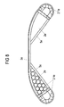
- the embodiment of Figure 8 shows a double-sided Guiding element consisting of two individual guiding elements corresponding to the embodiments of Figures 1 to 7 can be formed, is composed.
- the front one Outer shell and the section connecting the two guide elements is here as a single arched curve Part 3e trained.
- This double-sided guide element can be a single standing obstacle, for example a Tree, to be shielded separately. An additional protective device is not necessary.
- 2e and 2.1e are different Deformation body called.
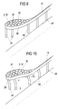
- Figures 9 and 10 schematically show an inventive Protective device 1f, in its beginning or end area has a guide element of one of the types mentioned.
- the protective device is in the ground via several posts 4f anchored between the guard and the floor are visible.
- the posts 4f are resiliently anchored in the ground, specifically such that the flexibility of the posts in the direction of Initial section of the protective device increases, the first post of the protective device the greatest compliance having.
- Posts are used, the two Have bending axes across which the posts differ are strongly bendable.
- the posts will be in the ground like this and placed in relation to the guide element that in the event of a collision a bending over the bending axis of less stiffness he follows.
- the posts have a cross section, for example a C-profile, double-T profile in a manner known per se or sigma profile.
- the Posts bent horizontally and point away from the traffic route.
- the posts closer to the start or end section are bent more than those in the direction of the main part of the protective device.
- the one Traffic route-facing side of the outer shell 3f of the guide element is also badly deformed that the traffic route opposite side of the outer shell 5f has almost its shape to keep.
- FIG. 11 shows a further embodiment of the Invention.
- the guide element is via an intermediate piece 7g with the end section 1g of the protective device connected, analogous to the embodiment of Figure 5.
- the intermediate piece 7g and the traffic route opposite side of the outer shell 5g integrally formed.
- the transition area represents a transition between different profiles of the guide element and a usual Guardrail guard rail available.
- deformation area 2g which is analogous to the previous one
- Some of these deformation elements 2.1g are about struts 14g that run across the traffic route are aligned with the inside of the traffic route facing side of the outer shell 5g connected. Alternatively, the struts 14g run transversely to the rear Profile tape 5g.
- the guide element is via post 4g, which is shown in the Embodiment have a C-profile, anchored in the ground.
- the deformation range 2g the tubular deformation elements 2.1g together arranged with the cross struts 14g.
- the deformation elements 2.1g prevent or reduce wrinkling of the outer sheet 3g in the event of an impact, since they contract prevent the outer sheet. This has the advantage that the outer sheet (sheet metal element 3g) has the smoothest possible surface retains and brakes a crashing vehicle well, redirected and returned to the traffic route can.
- the deformation elements increase the rigidity of the deformation area and enable the recording higher forces in the event of an impact.
- Figure 12 shows a sectional view of the guide element of Figure 11 along the line D-D. After that they own tubular deformation body 2.1 g a height that is less is the total height of the guide element. Next is too recognize that the outer shell 5g of the guide element in the illustrated Embodiment a wavy profile having. Any other profile is also located within the scope of the invention. Next is clearly too recognize that the deformation elements 2.1g immediately the inside of the side facing the traffic route Fit the outer casing 3g.
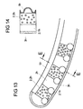
- Figure 13 shows a particularly preferred embodiment the invention.
- the outer shell of the guide element banana-shaped with the outer profile band 3h and the inner profile band 5h run largely parallel.
- the deformation area 2h there are several tubular, Polypropylene, equally spaced from each other existing deformation elements 2.1h directly on the Inside of an outer profile tape 3h made of polypropylene arranged.
- the outer profile strip 3h consist of a thin sheet.
- segments 2.2h Located between the outer and inner profile tape there are also several segments 2.2h made of polypropylene particle foam, which cause additional energy absorption, if a vehicle hits the guide element.
- the individual segments have an identical spatial shape, which is a rational production according to the known foam molding process possible by sintering foam particles makes. They are each between two neighboring deformation elements arranged, the deformation elements 2.1h simultaneously as a holder for the segments 2.2h serve.
- the inner profile band 5h is stronger than the outer profile band 3h trained. It provides the supporting structure for that the outer profile band, the deformation elements 2.1h and the segments 2.2h and is according to FIG. 11 above Anchored to the floor. It takes residual energy in particular and forwards it to the anchorage at an impact not already caused by the deformation elements 2.1h and the damping segments 2.2h are added.
- FIG. 14 again shows a sectional illustration of the guide element 13 along the line E-E.
- the sectional view is similar to that of Figure 12.
- Guide element of Figure 12 is the guide element of the figure 14 between the deformation element 2.1h and the inner one Profile tape 5h arranged the particle foam segment 2.2h. It fills the cross-section between the profile strip 5h and the segment 2.2h completely.
- the invention is not limited to the above illustrated embodiments. Other combinations as well as other constructive designs of the individual elements of the guide element are within the scope of the invention. Essential it is only for the invention that between one outer and an inner profile band of an outer shell of the Guide element formed at least one deformation area is.
Landscapes
- Engineering & Computer Science (AREA)
- Architecture (AREA)
- Civil Engineering (AREA)
- Structural Engineering (AREA)
- Life Sciences & Earth Sciences (AREA)
- Wood Science & Technology (AREA)
- Road Signs Or Road Markings (AREA)
- Refuge Islands, Traffic Blockers, Or Guard Fence (AREA)
- Control Of Vending Devices And Auxiliary Devices For Vending Devices (AREA)
- Magnetic Heads (AREA)
- Cable Accessories (AREA)
- Processing Of Terminals (AREA)
- Yarns And Mechanical Finishing Of Yarns Or Ropes (AREA)
Abstract
Description
- Figur 1
- -einen Längsschnitt durch eine erste Ausführungsform eines Leitelementes,
- Figur 2
- -eine Schnittdarstellung entsprechend der Linie A-A des Leitelementes der Figur 1,
- Figur 3
- -einen Längsschnitt durch eine weitere Ausführungsform eines Leitelementes,
- Figur 4
- -eine Schnittdarstellung entsprechend der Linie B-B des Leitelementes der Figur 3
- Figur 5
- -einen Längsschnitt durch einer weitere Ausführungsform eines Leitelementes,
- Figur 6
- -eine Schnittdarstellung entsprechend der Linie C-C des Leitelementes der Figur 5,
- Figur 7
- -einen Längsschnitt durch eine weitere Ausführungs form eines Leitelementes,
- Figur 8
- -ein doppleseitiges Leitelement,
- Figur 9
- -eine Schutzeinrichtung vor einem Aufprall,
- Figur 10
- -eine Schutzeinrichtung nach einem Aufprall,
- Figur 11
- -einen Längsschnitt durch eine weitere Ausführungsform eines Leitelementes,
- Figur 12
- -eine Schnittdarstellung entsprechend der Linie D-D des Leitelementes der Figur 11,
- Figur 13
- -einen Längsschnitt durch eine besonders bevorzugte Ausführungsform und
- Figur 14
- -eine Schnittdarstellung entsprechend der Linie E-E des Leitelementes der Figur 13.
- 1a, 1b, 1c, 1d, 1f, 1g
- Schutzeinrichtungsendstück
- 2a - 2h
- Deformationsbereich
- 2.1d, 2.1e, 2.1f, 2.1g, 2.1h
- Dämpfungselemente
- 2.2h
- Partikelschaumsegment
- 3a, 3b, 3e, 3f, 3g, 3h
- äußeres Profilband
- 4a, 4b, 4c, 4d, 4f, 4g
- Pfosten
- 5a - 5h
- inneres Profilband
- 5.1a, 5.1b
- Wölbung
- 6b, 6d
- Verstrebung
- 7c, 7g
- Zwischenstück
- 8d
- Distanzstück
- 12
- Befestigungsbereich
- 14g
- Querstrebe
- F
- Verkehrsweg
- X
- Übergangsbereich
- Y
- Aufprallrichtung
- Y'
- Umlenkrichtung
Claims (36)
- Leitelement für den Anfangs- oder Endbereich einer Schutzeinrichtung (1a, 1b, 1c, 1e, 1d, 1f, 1g) für Verkehrswege, mit einer Außenhülle, die ein dem Verkehrsweg zugewandtes äußeres Profilband (3a, 3b, 3c, 3d, 3e, 3f, 3g, 3h) und ein dem Verkehrsweg abgewandtes inneres Profilband (5a bis 5h) umfasst, wobei das innere Profilband mindestens einen Befestigungsbereich für eine Verankerung im Boden oder für eine Befestigung an anderen Teilen der Schutzeinrichtung aufweist,
dadurch gekennzeichnet, daß zwischen dem äußeren und dem inneren Profilband mindestens ein Deformationsbereich (2a - 2h) ausgebildet ist. - Leitelement nach Anspruch 1, dadurch gekennzeichnet, daß das Leitelement in Richtung des Endbereiches der Schutzeinrichtung zunehmend vom Verkehrsweg wegweist.
- Leitelement nach Anspruch 1 oder 2, dadurch gekennzeichnet, daß das Leitelement eine im Längsschnitt im wesentlichen tropfen- oder bananenförmige Außenhülle ausbildet.
- Leitelement nach Anspruch 3, dadurch gekennzeichnet, daß das Profilband (3a, 3b, 3e, 3f, 3g, 3h) den Deformationsbereich (2a - 2h) vollständig umschließt.
- Leitelement nach mindestens einem der vorhergehenden Ansprüche, dadurch gekennzeichnet, daß der Deformationsbereich (2a - 2h) deformierbare Dämpfungselemente (2.1d, 2.1e, 2.1f, 2.1g, 2.1h) aufweist.
- Leitelement nach Anspruch 5, dadurch gekennzeichnet, daß die Dämpfungselemente (2.1d, 2.1e, 2.1f, 2.1g, 2.1h) aus Kunststoff, insbesondere Polypropylen oder Polyvinylchlorid, bestehen.
- Leitelement nach Anspruch 5, dadurch gekennzeichnet, daß die Dämpfungselemente (2.1d, 2.1e, 2.1f, 2.1g, 2.1h) aus Metall, insbesondere Stahl, gefertigt sind.
- Leitelement nach mindestens einem der Ansprüche 5 bis 7, dadurch gekennzeichnet, daß die Dämpfungselemente (2.1d, 2.1e, 2.1f, 2.1g, 2.1h) Wabenstruktur und/oder eine fachwerkartige Struktur besitzen und/oder als Rohrelemente und/oder als wellenförmiges Band ausgeführt sind und/oder ein Kastenprofil besitzen und/oder aus Winkelprofilen bestehen.
- Leitelement nach mindestens einem der Ansprüche 5 bis 7, dadurch gekennzeichnet, daß die Dämpfungselemente (2.1d, 2.1e, 2,1f, 2.1g, 2.1h) Rohrelemente mit einem inneren Durchmesser von 10 bis 30 cm sind.
- Leitelement nach mindestens einem der Ansprüche 5 bis 9, dadurch gekennzeichnet, daß die Dämpfungselemente (2.1d, 2.1e, 2.1f) den Deformationsbereich (2d, 2f) vollständig ausfüllen.
- Leitelement nach Anspruch 5, dadurch gekennzeichnet, daß der Deformationsbereich (2a, 2b, 2c, 2h) ganz oder teilweise mit einem Kunststoffdämmmaterial (2.2h) ausgefüllt ist.
- Leitelement nach Anspruch 11, dadurch gekennzeichnet, daß das Kunststoffdämmmaterial (2.2h) ein energieabsorbierender Kunststoffschaum mit einer spezifischen Energieaufnahme von mindestens 1*10-5 J/mm3 und einem Druckverformungsrest bei 50 % Stauchung von kleiner 50 % ist.
- Leitelement nach Anpsruch 11 oder 12, dadurch gekennzeichnet, daß der Kunststoffschaum ein Polyolefin-Partikelschaum ist.
- Leitelement nach Anspruch 13, dadurch gekennzeichnet, daß der Kunststoffschaum ein Polypropylen-Partikelschaum mit einer Dichte von 15 bis 150 g/l, vorzugsweise von 20 bis 100 g/l, ist.
- Leitelement nach mindestens einem der vorhergehenden Ansprüch, dadurch gekennzeichnet, daß in der dem Verkehrsweg zugewandten Seite der Außenhülle Reflektoren eingelassen oder aufgesetzt sind.
- Leitelement nach mindestens einem der Ansprüche 5 bis 15, dadurch gekennzeichnet, daß mindestens zwei Dämpfungselemente (2.1g, 2.1h) als Rohrelemente ausgebildet und unmittelbar an der Innenseite der dem Verkehrsweg zugewandten Seite der Außenhülle voneinander beabstandet angeordnet sind.
- Leitelement nach Anspruch 16, dadurch gekennzeichnet, daß die Dämpfungslelemente (2.1g) über Querstreben (14g) mit der Innenseite der dem Verkehrsweg abgewandten Seite der Außenhülle verbunden sind.
- Leitelement nach Anspruch 16, dadurch gekennzeichnet, daß der Deformationsbereich (2h) zusätzlich zu den Rohrelementen (2.1h) ein Kunststoffdämmmaterial (2.2h) enthält.
- Leitelement nach Anspruch 18, dadurch gekennzeichnet, daß das Kunststoffdämmmaterial in Form von Kunststoffschaum-Segmenten (2.1h) zwischen dem inneren Profilband (3a, 3b, 3c, 3h) und dem äußeren Profilband (5a, 5b, 5c, 5h) eingebracht ist.
- Leitelement nach Anspruch 19, dadurch gekennzeichnet, daß der Abstand zwischen dem inneren Profilband (3h) und dem äußeren Profilband (5h) größtenteils im wesentlichen konstant ist, wobei Kunststoffschaum-Segmente (2.1h) gleicher Größe zwischen den Profilbändern (3h, 5h) angeordnet sind.
- Leitelement nach mindestens einem der vorhergehenden Ansprüche, dadurch gekennzeichnet, daß das Leitelement einen im wesentlichen rechteckigen Querschnitt aufweist.
- Leitelement nach mindestens einem der vorhergehenden Ansprüche, dadurch gekennzeichnet, daß das innere Profilband (5a bis 5h) aus Metall, insbesondere Stahl, gefertigt ist.
- Leitelement nach mindestens einem der vorhergehenden Ansprüche, dadurch gekennzeichnet, daß das äußere Profilband (3a, 3b, 3e, 3f, 3g, 3h) aus Metall oder Kunststoff besteht.
- Leitelement nach Anspruch 22 und 23, dadurch gekennzeichnet, daß das innere Profilband stärker ausgeführt ist als das äußere Profilband.
- Leitelement nach mindestens einem der vorhergehenden Ansprüche, dadurch gekennzeichnet, daß sich zwischen dem Befestigungsbereich des Leitelements und einer Bodenverankerung (4d) ein Distanzstück (8d) befindet.
- Leitelement nach mindestens einem der vorhergehenden Ansprüche, dadurch gekennzeichnet, daß das Leitelement in einem Übergangsbereich zur Schutzeinrichtung ein der Anpassung an die Schutzeinrichtung dienendes Zwischenstück (7c, 7g) ausbildet.
- Leitelement nach Anspruch 26, dadurch gekennzeichnet, daß das Zwischenstück (7g) einstückig mit der dem Verkehrsweg abgewandten Seite der Außenhülle (5g) ausgebildet ist.
- Leitelement nach mindestens einem der vorhergehenden Ansprüche dadurch gekennzeichnet, daß zwei Leitelemente, die an den mit der Schutzeinrichtung zu verbindenden Enden gekoppelt werden, ein doppelseitiges Leitelement bilden.
- Schutzeinrichtung an einzelnen oder mehreren nebeneinanderstehenden Hindernissen, z.B. Bäumen oder Pfosten, dadurch gekennzeichnet, daß die Schutzeinrichtung zwei miteinander verbundene Leitelemente nach Anspruch 1 umfasst.
- Schutzeinrichtung nach Anspruch 29, dadurch gekennzeichnet, daß die Schutzeinrichtung für Alleebäume ausgebildet ist.
- Schutzeinrichtung nach Anspruch 29 oder 30, gekennzeichnet durch eine Länge von 3 bis 10m.
- Schutzeinrichtung nach mindestens einem der Ansprüche 29 bis 31, dadurch gekennzeichnet, daß die beiden Leitelemente mittels eines geraden oder leicht gebogenen Mittelstücks (3g) miteinander verbunden sind.
- Schutzeinrichtung (1a, 1b, 1c, 1d, 1f, 1g) für Verkehrswege, das über mindestens einen Pfosten (4a, 4b, 4c, 4d, 4f, 4g) im Boden verankert ist,
gekennzeichnet durch
mindestens ein Leitelement nach Anspruch 1, wobei mindestens ein Pfosten (4a, 4b, 4c, 4d, 4f, 4g) derart im Boden verankert und mit dem Leitelement verbunden ist, daß das Leitelement im Kollisionsfall nachgiebig vom Verkehrsweg wegbewegt wird. - Schutzeinrichtung nach Anspruch 33, dadurch gekennzeichnet, daß die Nachgiebigkeit der Pfosten (4a, 4b, 4c, 4d, 4f, 4g) in Richtung des Anfangs- oder Endabschnittes der Schutzeinrichtung zunimmt, wobei der jeweils erste oder letzte Pfosten der Schutzeinrichtung die größte Nachgiebigkeit aufweist.
- Schutzeinrichtung nach Anspruch 34, dadurch gekennzeichnet, daß der Pfosten (4a, 4b, 4c, 4d, 4f, 4g) jeweils zwei Biegeachsen aufweist, über die der Pfostens unterschiedlich stark verbiegbar ist, wobei im Kollisionsfall eine Verbiegung über die Biegeachse geringerer Steifigkeit erfolgt.
- Schutzeinrichtung nach Anspruch 35, dadurch gekennzeichnet, daß der Pfosten im Querschnitt ein C-Profil, Doppel-T-Profil oder Sigma-Profil aufweist.
Applications Claiming Priority (6)
| Application Number | Priority Date | Filing Date | Title |
|---|---|---|---|
| DE20016162U DE20016162U1 (de) | 2000-09-12 | 2000-09-12 | Leitelement an Verkehrswegen |
| DE20016162U | 2000-09-12 | ||
| DE10113152 | 2001-03-14 | ||
| DE10113152 | 2001-03-14 | ||
| DE10116701 | 2001-03-29 | ||
| DE10116701A DE10116701A1 (de) | 2000-09-12 | 2001-03-29 | Leitelement für Schutzeinrichtungen |
Publications (3)
| Publication Number | Publication Date |
|---|---|
| EP1186714A2 true EP1186714A2 (de) | 2002-03-13 |
| EP1186714A3 EP1186714A3 (de) | 2002-07-31 |
| EP1186714B1 EP1186714B1 (de) | 2009-01-21 |
Family
ID=26008820
Family Applications (1)
| Application Number | Title | Priority Date | Filing Date |
|---|---|---|---|
| EP01250314A Expired - Lifetime EP1186714B1 (de) | 2000-09-12 | 2001-09-04 | Leitelement für Schutzeinrichtungen |
Country Status (4)
| Country | Link |
|---|---|
| EP (1) | EP1186714B1 (de) |
| AT (1) | ATE421617T1 (de) |
| DE (3) | DE10116701A1 (de) |
| DK (1) | DK1186714T3 (de) |
Cited By (5)
| Publication number | Priority date | Publication date | Assignee | Title |
|---|---|---|---|---|
| EP1382748A3 (de) * | 2002-07-16 | 2004-05-12 | METALMECCANICA FRACASSO S.p.A. | Leitplankenendbereich |
| GB2444061A (en) * | 2006-11-24 | 2008-05-28 | Corus Uk Ltd | Vehicle safety barriers |
| US8647012B2 (en) | 2010-05-05 | 2014-02-11 | Energy Absorption Systems, Inc. | Gate for barrier system and methods for the assembly and use thereof |
| EP3795751A1 (de) | 2019-09-18 | 2021-03-24 | Meiser Straßenausstattung GmbH | Anpralldämpfer und schutzeinrichtung an objekten |
| PL447333A1 (pl) * | 2023-12-28 | 2025-06-30 | Inter Metal Spółka Z Ograniczoną Odpowiedzialnością | Drogowe urządzenie ochronne |
Families Citing this family (5)
| Publication number | Priority date | Publication date | Assignee | Title |
|---|---|---|---|---|
| DE10231903B4 (de) * | 2002-07-11 | 2005-02-03 | Outimex-Bautechnik Gmbh | Leitelement für den Anfangs- oder Endbereich einer Leitplanke oder eines Leitplankensystems an Verkehrswegen |
| DE10234344A1 (de) * | 2002-07-26 | 2004-02-05 | Manfred Bongard | Schutzeinrichtung an Verkehrswegen |
| DE202005001801U1 (de) * | 2005-02-01 | 2005-04-14 | Outimex Ag | Leitelement für den Anfangs- und/oder Endbereich einer Schutzeinrichtung, Schutzeinrichtung mit einem derartigen Leitelement sowie Bausatz für eine derartige Schutzeinrichtung |
| DE202007007958U1 (de) | 2007-06-06 | 2007-08-16 | Bongard Gmbh & Co. Kg | Anfangs- und Endkonstruktion |
| DE102021112502A1 (de) | 2021-05-12 | 2022-11-17 | Meiser Straßenausstattung GmbH | Schutzeinrichtung für Einmündungsbereiche von Verkehrswegen |
Family Cites Families (15)
| Publication number | Priority date | Publication date | Assignee | Title |
|---|---|---|---|---|
| US2154818A (en) * | 1936-07-17 | 1939-04-18 | Eimco Corp | Flexible highway guard |
| DE1985629U (de) * | 1968-02-24 | 1968-05-22 | Guenther Gubela | Leitplanke fuer verkehrsstrassen. |
| FR1605025A (de) * | 1968-09-16 | 1972-08-28 | ||
| US3643924A (en) * | 1970-09-24 | 1972-02-22 | Fibco Inc | Highway safety device |
| LU71229A1 (de) * | 1974-10-31 | 1976-08-19 | ||
| DE3106694A1 (de) * | 1981-02-23 | 1982-09-09 | Hermann Hans 8750 Aschaffenburg Urlberger | "stossdaempfende vorrichtung und verwendung derselben in einem schutzplankensystem" |
| FR2556754B1 (fr) * | 1983-12-20 | 1986-05-23 | France Etat | Glissiere de protection routiere adaptee aux obstacles saillants |
| DE3635990C1 (en) * | 1986-10-23 | 1988-03-24 | Spig Schutzplanken Prod Gmbh | Impact damper |
| DE3809470A1 (de) * | 1988-03-21 | 1989-10-12 | Sps Schutzplanken Gmbh | Stossdaempfende vorrichtung fuer schutzplankeneinrichtungen |
| DE4131937C2 (de) * | 1991-09-25 | 1995-12-21 | Spig Schutzplanken Prod Gmbh | Leitplankenanordnung aus Stahl |
| US5407298A (en) * | 1993-06-15 | 1995-04-18 | The Texas A&M University System | Slotted rail terminal |
| DE9313389U1 (de) * | 1993-09-06 | 1993-12-02 | Mössmer GmbH & Co. Schaumstoff-Verarbeitung & Recycling, 88069 Tettnang | Leitplanke mit Aufprallschutzvorrichtung |
| FR2739403B1 (fr) * | 1996-02-07 | 1999-04-23 | Gay Richard Marcel Camille | Systeme polyvalent de securite routiere par rempart de pneumatiques usages et procede de mise en oeuvre |
| US5791812A (en) * | 1996-10-11 | 1998-08-11 | The Texas A&M University System | Collision performance side impact (automobile penetration guard) |
| DK0924347T3 (da) * | 1997-12-22 | 2004-07-26 | Autostrada Del Brennero S P A | Sikkerhedsbarriere-endestykke til et motorvejsautoværn |
-
2001
- 2001-03-29 DE DE10116701A patent/DE10116701A1/de not_active Ceased
- 2001-03-29 DE DE20107392U patent/DE20107392U1/de not_active Expired - Lifetime
- 2001-09-04 DK DK01250314T patent/DK1186714T3/da active
- 2001-09-04 AT AT01250314T patent/ATE421617T1/de active
- 2001-09-04 DE DE50114669T patent/DE50114669D1/de not_active Expired - Lifetime
- 2001-09-04 EP EP01250314A patent/EP1186714B1/de not_active Expired - Lifetime
Cited By (7)
| Publication number | Priority date | Publication date | Assignee | Title |
|---|---|---|---|---|
| EP1382748A3 (de) * | 2002-07-16 | 2004-05-12 | METALMECCANICA FRACASSO S.p.A. | Leitplankenendbereich |
| US6948880B2 (en) * | 2002-07-16 | 2005-09-27 | Metalmeccanica Fracasso S.P.A. | Guardrail terminal |
| RU2307210C2 (ru) * | 2002-07-16 | 2007-09-27 | МЕТАЛЬМЕККАНИКА ФРАКАССО С.п.А. | Концевой участок ограждения |
| GB2444061A (en) * | 2006-11-24 | 2008-05-28 | Corus Uk Ltd | Vehicle safety barriers |
| US8647012B2 (en) | 2010-05-05 | 2014-02-11 | Energy Absorption Systems, Inc. | Gate for barrier system and methods for the assembly and use thereof |
| EP3795751A1 (de) | 2019-09-18 | 2021-03-24 | Meiser Straßenausstattung GmbH | Anpralldämpfer und schutzeinrichtung an objekten |
| PL447333A1 (pl) * | 2023-12-28 | 2025-06-30 | Inter Metal Spółka Z Ograniczoną Odpowiedzialnością | Drogowe urządzenie ochronne |
Also Published As
| Publication number | Publication date |
|---|---|
| EP1186714A3 (de) | 2002-07-31 |
| DK1186714T3 (da) | 2009-05-18 |
| DE50114669D1 (de) | 2009-03-12 |
| EP1186714B1 (de) | 2009-01-21 |
| ATE421617T1 (de) | 2009-02-15 |
| DE10116701A1 (de) | 2002-03-28 |
| DE20107392U1 (de) | 2001-08-02 |
Similar Documents
| Publication | Publication Date | Title |
|---|---|---|
| DE2231763C2 (de) | Leitplanke | |
| DE69727815T2 (de) | Sicherheitsendanlage für Leitplanken | |
| EP0014172A1 (de) | Als Leiteinrichtung für den Strassenverkehr und zum Schallschutz für die Anrainer von Fahrbahnen dienende Schutzwand | |
| DE2251749A1 (de) | Sicherheitsvorrichtung im strassenverkehr | |
| DE2158706A1 (de) | Hohlprofilleitplanke mit dazugehoerigen sie tragenden stuetzen | |
| DE2455268B2 (de) | Auffahrschutz fuer leitplankenanfaenge | |
| EP1186714B1 (de) | Leitelement für Schutzeinrichtungen | |
| DE202020103520U1 (de) | Anpralldämpfer und Schutzeinrichtung an Objekten | |
| EP1762660A1 (de) | Verkehrs-Leit-Einrichtung | |
| EP1857594B1 (de) | Steher für Leiteinrichtung mit Grundplatte | |
| EP1452666B1 (de) | Beton-Schutzwand | |
| EP3696322B1 (de) | Modulares verkehrszeichen | |
| EP1381737B1 (de) | Terminal für seitlich an verkehrswegen angeordnete rückhaltesysteme aus stahlprofilen | |
| DE4335904C2 (de) | Passive Schutzeinrichtung an Straßen | |
| DE19907954B4 (de) | Passive Schutzeinrichtung | |
| DE3809470A1 (de) | Stossdaempfende vorrichtung fuer schutzplankeneinrichtungen | |
| DE69935446T2 (de) | Leitplanken-aufbau | |
| EP1026327B1 (de) | Anpralldämpfer | |
| DE20016162U1 (de) | Leitelement an Verkehrswegen | |
| EP1844197B1 (de) | Leitelement für den anfangs- und/oder endbereich einer schutzeinrichtung, schutzeinrichtung mit einem derartigen leitelement sowie bausatz für eine derartige schutzeinrichtung | |
| DE2413095C3 (de) | Leiteinrichtung fUr Personen- und Lastkraftwagen | |
| DE3627146C2 (de) | ||
| AT300007B (de) | Fahrzeugleiteinrichtung für den Mittelstreifen von Autobahnen u.dgl. | |
| WO2006089321A1 (de) | Sicherheitseinrichtung für verkehrswege | |
| DE2547543A1 (de) | Leitschiene mit im abstand hinter ihr angeordneter zugbandsicherung |
Legal Events
| Date | Code | Title | Description |
|---|---|---|---|
| PUAI | Public reference made under article 153(3) epc to a published international application that has entered the european phase |
Free format text: ORIGINAL CODE: 0009012 |
|
| AK | Designated contracting states |
Kind code of ref document: A2 Designated state(s): AT BE CH CY DE DK ES FI FR GB GR IE IT LI LU MC NL PT SE TR |
|
| AX | Request for extension of the european patent |
Free format text: AL;LT;LV;MK;RO;SI |
|
| PUAL | Search report despatched |
Free format text: ORIGINAL CODE: 0009013 |
|
| AK | Designated contracting states |
Kind code of ref document: A3 Designated state(s): AT BE CH CY DE DK ES FI FR GB GR IE IT LI LU MC NL PT SE TR |
|
| AX | Request for extension of the european patent |
Free format text: AL;LT;LV;MK;RO;SI |
|
| 17P | Request for examination filed |
Effective date: 20021120 |
|
| AKX | Designation fees paid |
Designated state(s): AT BE CH CY DE DK ES FI FR GB GR IE IT LI LU MC NL PT SE TR |
|
| 17Q | First examination report despatched |
Effective date: 20040426 |
|
| RAP1 | Party data changed (applicant data changed or rights of an application transferred) |
Owner name: BASF SE Owner name: OUTIMEX BAUTECHNIK GMBH Owner name: FEBRA-KUNSTSTOFFE GMBH & CO. |
|
| GRAP | Despatch of communication of intention to grant a patent |
Free format text: ORIGINAL CODE: EPIDOSNIGR1 |
|
| GRAS | Grant fee paid |
Free format text: ORIGINAL CODE: EPIDOSNIGR3 |
|
| GRAA | (expected) grant |
Free format text: ORIGINAL CODE: 0009210 |
|
| AK | Designated contracting states |
Kind code of ref document: B1 Designated state(s): AT BE CH CY DE DK ES FI FR GB GR IE IT LI LU MC NL PT SE TR |
|
| REG | Reference to a national code |
Ref country code: GB Ref legal event code: FG4D Free format text: NOT ENGLISH |
|
| REG | Reference to a national code |
Ref country code: CH Ref legal event code: EP |
|
| REG | Reference to a national code |
Ref country code: IE Ref legal event code: FG4D Free format text: LANGUAGE OF EP DOCUMENT: GERMAN |
|
| REF | Corresponds to: |
Ref document number: 50114669 Country of ref document: DE Date of ref document: 20090312 Kind code of ref document: P |
|
| REG | Reference to a national code |
Ref country code: CH Ref legal event code: NV Representative=s name: SCHMAUDER & PARTNER AG PATENTANWALTSBUERO |
|
| REG | Reference to a national code |
Ref country code: DK Ref legal event code: T3 |
|
| PG25 | Lapsed in a contracting state [announced via postgrant information from national office to epo] |
Ref country code: NL Free format text: LAPSE BECAUSE OF FAILURE TO SUBMIT A TRANSLATION OF THE DESCRIPTION OR TO PAY THE FEE WITHIN THE PRESCRIBED TIME-LIMIT Effective date: 20090121 |
|
| NLV1 | Nl: lapsed or annulled due to failure to fulfill the requirements of art. 29p and 29m of the patents act | ||
| PG25 | Lapsed in a contracting state [announced via postgrant information from national office to epo] |
Ref country code: FI Free format text: LAPSE BECAUSE OF FAILURE TO SUBMIT A TRANSLATION OF THE DESCRIPTION OR TO PAY THE FEE WITHIN THE PRESCRIBED TIME-LIMIT Effective date: 20090121 Ref country code: ES Free format text: LAPSE BECAUSE OF FAILURE TO SUBMIT A TRANSLATION OF THE DESCRIPTION OR TO PAY THE FEE WITHIN THE PRESCRIBED TIME-LIMIT Effective date: 20090502 |
|
| REG | Reference to a national code |
Ref country code: CH Ref legal event code: PCAR Free format text: SCHMAUDER & PARTNER AG PATENT- UND MARKENANWAELTE VSP;ZWAENGIWEG 7;8038 ZUERICH (CH) |
|
| REG | Reference to a national code |
Ref country code: IE Ref legal event code: FD4D |
|
| PG25 | Lapsed in a contracting state [announced via postgrant information from national office to epo] |
Ref country code: PT Free format text: LAPSE BECAUSE OF FAILURE TO SUBMIT A TRANSLATION OF THE DESCRIPTION OR TO PAY THE FEE WITHIN THE PRESCRIBED TIME-LIMIT Effective date: 20090622 Ref country code: SE Free format text: LAPSE BECAUSE OF FAILURE TO SUBMIT A TRANSLATION OF THE DESCRIPTION OR TO PAY THE FEE WITHIN THE PRESCRIBED TIME-LIMIT Effective date: 20090421 |
|
| PG25 | Lapsed in a contracting state [announced via postgrant information from national office to epo] |
Ref country code: IE Free format text: LAPSE BECAUSE OF FAILURE TO SUBMIT A TRANSLATION OF THE DESCRIPTION OR TO PAY THE FEE WITHIN THE PRESCRIBED TIME-LIMIT Effective date: 20090121 |
|
| PLBE | No opposition filed within time limit |
Free format text: ORIGINAL CODE: 0009261 |
|
| STAA | Information on the status of an ep patent application or granted ep patent |
Free format text: STATUS: NO OPPOSITION FILED WITHIN TIME LIMIT |
|
| 26N | No opposition filed |
Effective date: 20091022 |
|
| BERE | Be: lapsed |
Owner name: BASF SE Effective date: 20090930 Owner name: OUTIMEX BAUTECHNIK G.M.B.H. Effective date: 20090930 Owner name: FEBRA-KUNSTSTOFFE G.M.B.H. & CO. Effective date: 20090930 |
|
| PG25 | Lapsed in a contracting state [announced via postgrant information from national office to epo] |
Ref country code: MC Free format text: LAPSE BECAUSE OF NON-PAYMENT OF DUE FEES Effective date: 20090930 |
|
| PG25 | Lapsed in a contracting state [announced via postgrant information from national office to epo] |
Ref country code: BE Free format text: LAPSE BECAUSE OF NON-PAYMENT OF DUE FEES Effective date: 20090930 |
|
| PG25 | Lapsed in a contracting state [announced via postgrant information from national office to epo] |
Ref country code: GR Free format text: LAPSE BECAUSE OF FAILURE TO SUBMIT A TRANSLATION OF THE DESCRIPTION OR TO PAY THE FEE WITHIN THE PRESCRIBED TIME-LIMIT Effective date: 20090422 |
|
| PG25 | Lapsed in a contracting state [announced via postgrant information from national office to epo] |
Ref country code: IT Free format text: LAPSE BECAUSE OF FAILURE TO SUBMIT A TRANSLATION OF THE DESCRIPTION OR TO PAY THE FEE WITHIN THE PRESCRIBED TIME-LIMIT Effective date: 20090121 |
|
| PG25 | Lapsed in a contracting state [announced via postgrant information from national office to epo] |
Ref country code: LU Free format text: LAPSE BECAUSE OF NON-PAYMENT OF DUE FEES Effective date: 20090904 |
|
| PG25 | Lapsed in a contracting state [announced via postgrant information from national office to epo] |
Ref country code: TR Free format text: LAPSE BECAUSE OF FAILURE TO SUBMIT A TRANSLATION OF THE DESCRIPTION OR TO PAY THE FEE WITHIN THE PRESCRIBED TIME-LIMIT Effective date: 20090121 |
|
| PG25 | Lapsed in a contracting state [announced via postgrant information from national office to epo] |
Ref country code: CY Free format text: LAPSE BECAUSE OF FAILURE TO SUBMIT A TRANSLATION OF THE DESCRIPTION OR TO PAY THE FEE WITHIN THE PRESCRIBED TIME-LIMIT Effective date: 20090121 |
|
| REG | Reference to a national code |
Ref country code: DE Ref legal event code: R082 Ref document number: 50114669 Country of ref document: DE Representative=s name: MAIKOWSKI & NINNEMANN PATENTANWAELTE, DE |
|
| REG | Reference to a national code |
Ref country code: DE Ref legal event code: R081 Ref document number: 50114669 Country of ref document: DE Owner name: SAFEROAD RRS GMBH, DE Free format text: FORMER OWNER: BASF SE, FEBRA-KUNSTSTOFFE GMBH & CO., OUTIMEX-BAUTECHNIK GMBH, , DE Effective date: 20120208 Ref country code: DE Ref legal event code: R081 Ref document number: 50114669 Country of ref document: DE Owner name: FEBRA-KUNSTSTOFFE GMBH & CO., DE Free format text: FORMER OWNER: BASF SE, FEBRA-KUNSTSTOFFE GMBH & CO., OUTIMEX-BAUTECHNIK GMBH, , DE Effective date: 20120208 Ref country code: DE Ref legal event code: R081 Ref document number: 50114669 Country of ref document: DE Owner name: BASF SE, DE Free format text: FORMER OWNER: BASF SE, FEBRA-KUNSTSTOFFE GMBH & CO., OUTIMEX-BAUTECHNIK GMBH, , DE Effective date: 20120208 Ref country code: DE Ref legal event code: R082 Ref document number: 50114669 Country of ref document: DE Representative=s name: MAIKOWSKI & NINNEMANN PATENTANWAELTE, DE Effective date: 20120208 Ref country code: DE Ref legal event code: R081 Ref document number: 50114669 Country of ref document: DE Owner name: BASF SE, DE Free format text: FORMER OWNERS: BASF SE, 67063 LUDWIGSHAFEN, DE; FEBRA-KUNSTSTOFFE GMBH & CO., 74336 BRACKENHEIM, DE; OUTIMEX-BAUTECHNIK GMBH, 10779 BERLIN, DE Effective date: 20120208 Ref country code: DE Ref legal event code: R081 Ref document number: 50114669 Country of ref document: DE Owner name: SAFEROAD RRS GMBH, DE Free format text: FORMER OWNERS: BASF SE, 67063 LUDWIGSHAFEN, DE; FEBRA-KUNSTSTOFFE GMBH & CO., 74336 BRACKENHEIM, DE; OUTIMEX-BAUTECHNIK GMBH, 10779 BERLIN, DE Effective date: 20120208 Ref country code: DE Ref legal event code: R081 Ref document number: 50114669 Country of ref document: DE Owner name: FEBRA-KUNSTSTOFFE GMBH & CO., DE Free format text: FORMER OWNERS: BASF SE, 67063 LUDWIGSHAFEN, DE; FEBRA-KUNSTSTOFFE GMBH & CO., 74336 BRACKENHEIM, DE; OUTIMEX-BAUTECHNIK GMBH, 10779 BERLIN, DE Effective date: 20120208 Ref country code: DE Ref legal event code: R082 Ref document number: 50114669 Country of ref document: DE Representative=s name: MUELLER, WOLFRAM, DIPL.-PHYS. DR.IUR., DE Effective date: 20120208 Ref country code: DE Ref legal event code: R082 Ref document number: 50114669 Country of ref document: DE Representative=s name: MUELLER, WOLFRAM, DIPL.-PHYS. DR. JUR., DE Effective date: 20120208 |
|
| REG | Reference to a national code |
Ref country code: FR Ref legal event code: PLFP Year of fee payment: 15 |
|
| REG | Reference to a national code |
Ref country code: DE Ref legal event code: R082 Ref document number: 50114669 Country of ref document: DE Representative=s name: MUELLER, WOLFRAM, DIPL.-PHYS. DR.IUR., DE Ref country code: DE Ref legal event code: R082 Ref document number: 50114669 Country of ref document: DE Representative=s name: MUELLER, WOLFRAM, DIPL.-PHYS. DR. JUR., DE |
|
| REG | Reference to a national code |
Ref country code: FR Ref legal event code: PLFP Year of fee payment: 16 |
|
| PGFP | Annual fee paid to national office [announced via postgrant information from national office to epo] |
Ref country code: GB Payment date: 20160921 Year of fee payment: 16 Ref country code: CH Payment date: 20160926 Year of fee payment: 16 Ref country code: DK Payment date: 20160923 Year of fee payment: 16 |
|
| PGFP | Annual fee paid to national office [announced via postgrant information from national office to epo] |
Ref country code: AT Payment date: 20160921 Year of fee payment: 16 |
|
| REG | Reference to a national code |
Ref country code: FR Ref legal event code: PLFP Year of fee payment: 17 |
|
| REG | Reference to a national code |
Ref country code: DK Ref legal event code: EBP Effective date: 20170930 |
|
| REG | Reference to a national code |
Ref country code: CH Ref legal event code: PL |
|
| REG | Reference to a national code |
Ref country code: AT Ref legal event code: MM01 Ref document number: 421617 Country of ref document: AT Kind code of ref document: T Effective date: 20170904 |
|
| GBPC | Gb: european patent ceased through non-payment of renewal fee |
Effective date: 20170904 |
|
| PG25 | Lapsed in a contracting state [announced via postgrant information from national office to epo] |
Ref country code: LI Free format text: LAPSE BECAUSE OF NON-PAYMENT OF DUE FEES Effective date: 20170930 Ref country code: GB Free format text: LAPSE BECAUSE OF NON-PAYMENT OF DUE FEES Effective date: 20170904 Ref country code: CH Free format text: LAPSE BECAUSE OF NON-PAYMENT OF DUE FEES Effective date: 20170930 |
|
| PG25 | Lapsed in a contracting state [announced via postgrant information from national office to epo] |
Ref country code: AT Free format text: LAPSE BECAUSE OF NON-PAYMENT OF DUE FEES Effective date: 20170904 |
|
| REG | Reference to a national code |
Ref country code: FR Ref legal event code: PLFP Year of fee payment: 18 |
|
| PG25 | Lapsed in a contracting state [announced via postgrant information from national office to epo] |
Ref country code: DK Free format text: LAPSE BECAUSE OF NON-PAYMENT OF DUE FEES Effective date: 20170930 |
|
| PGFP | Annual fee paid to national office [announced via postgrant information from national office to epo] |
Ref country code: DE Payment date: 20190724 Year of fee payment: 19 Ref country code: FR Payment date: 20190923 Year of fee payment: 19 |
|
| REG | Reference to a national code |
Ref country code: DE Ref legal event code: R119 Ref document number: 50114669 Country of ref document: DE |
|
| PG25 | Lapsed in a contracting state [announced via postgrant information from national office to epo] |
Ref country code: DE Free format text: LAPSE BECAUSE OF NON-PAYMENT OF DUE FEES Effective date: 20210401 Ref country code: FR Free format text: LAPSE BECAUSE OF NON-PAYMENT OF DUE FEES Effective date: 20200930 |