EP1186484A2 - Gassack für ein Airbagmodul - Google Patents
Gassack für ein Airbagmodul Download PDFInfo
- Publication number
- EP1186484A2 EP1186484A2 EP01250405A EP01250405A EP1186484A2 EP 1186484 A2 EP1186484 A2 EP 1186484A2 EP 01250405 A EP01250405 A EP 01250405A EP 01250405 A EP01250405 A EP 01250405A EP 1186484 A2 EP1186484 A2 EP 1186484A2
- Authority
- EP
- European Patent Office
- Prior art keywords
- airbag
- airbag module
- gas generator
- gas
- generator
- Prior art date
- Legal status (The legal status is an assumption and is not a legal conclusion. Google has not performed a legal analysis and makes no representation as to the accuracy of the status listed.)
- Granted
Links
- 229920003023 plastic Polymers 0.000 description 3
- 239000004033 plastic Substances 0.000 description 3
- 238000000034 method Methods 0.000 description 2
- 238000004873 anchoring Methods 0.000 description 1
- 238000013461 design Methods 0.000 description 1
- 238000005553 drilling Methods 0.000 description 1
- 238000005516 engineering process Methods 0.000 description 1
- 239000004744 fabric Substances 0.000 description 1
- 238000007667 floating Methods 0.000 description 1
- 238000002347 injection Methods 0.000 description 1
- 239000007924 injection Substances 0.000 description 1
- 238000001746 injection moulding Methods 0.000 description 1
- 238000003780 insertion Methods 0.000 description 1
- 230000037431 insertion Effects 0.000 description 1
- 238000009434 installation Methods 0.000 description 1
- 238000004519 manufacturing process Methods 0.000 description 1
- 238000012986 modification Methods 0.000 description 1
- 230000004048 modification Effects 0.000 description 1
- 238000012549 training Methods 0.000 description 1
Images


Classifications
-
- B—PERFORMING OPERATIONS; TRANSPORTING
- B60—VEHICLES IN GENERAL
- B60R—VEHICLES, VEHICLE FITTINGS, OR VEHICLE PARTS, NOT OTHERWISE PROVIDED FOR
- B60R21/00—Arrangements or fittings on vehicles for protecting or preventing injuries to occupants or pedestrians in case of accidents or other traffic risks
- B60R21/02—Occupant safety arrangements or fittings, e.g. crash pads
- B60R21/16—Inflatable occupant restraints or confinements designed to inflate upon impact or impending impact, e.g. air bags
- B60R21/20—Arrangements for storing inflatable members in their non-use or deflated condition; Arrangement or mounting of air bag modules or components
- B60R21/217—Inflation fluid source retainers, e.g. reaction canisters; Connection of bags, covers, diffusers or inflation fluid sources therewith or together
- B60R21/2176—Inflation fluid source retainers, e.g. reaction canisters; Connection of bags, covers, diffusers or inflation fluid sources therewith or together the air bag components being completely enclosed in a soft or semi-rigid housing or cover
-
- B—PERFORMING OPERATIONS; TRANSPORTING
- B60—VEHICLES IN GENERAL
- B60R—VEHICLES, VEHICLE FITTINGS, OR VEHICLE PARTS, NOT OTHERWISE PROVIDED FOR
- B60R21/00—Arrangements or fittings on vehicles for protecting or preventing injuries to occupants or pedestrians in case of accidents or other traffic risks
- B60R21/02—Occupant safety arrangements or fittings, e.g. crash pads
- B60R21/16—Inflatable occupant restraints or confinements designed to inflate upon impact or impending impact, e.g. air bags
- B60R21/20—Arrangements for storing inflatable members in their non-use or deflated condition; Arrangement or mounting of air bag modules or components
- B60R21/203—Arrangements for storing inflatable members in their non-use or deflated condition; Arrangement or mounting of air bag modules or components in steering wheels or steering columns
- B60R21/2035—Arrangements for storing inflatable members in their non-use or deflated condition; Arrangement or mounting of air bag modules or components in steering wheels or steering columns using modules containing inflator, bag and cover attachable to the steering wheel as a complete sub-unit
-
- B—PERFORMING OPERATIONS; TRANSPORTING
- B60—VEHICLES IN GENERAL
- B60R—VEHICLES, VEHICLE FITTINGS, OR VEHICLE PARTS, NOT OTHERWISE PROVIDED FOR
- B60R21/00—Arrangements or fittings on vehicles for protecting or preventing injuries to occupants or pedestrians in case of accidents or other traffic risks
- B60R21/02—Occupant safety arrangements or fittings, e.g. crash pads
- B60R21/16—Inflatable occupant restraints or confinements designed to inflate upon impact or impending impact, e.g. air bags
- B60R21/23—Inflatable members
Definitions
- the invention relates to an airbag for an airbag module according to the preamble of claim 1.
- Airbag modules serve to protect motor vehicle passengers in the Crash case by placing an airbag in between in a short time a motor vehicle part, such as a steering wheel, dashboard or Side door, and the occupant by a gas generator generated or released gas is inflated.
- An airbag module usually includes next to the gas bag and the gas generator a number of other components, in particular a housing in which the gas bag is folded, a cover for the housing and a generator support on which the gas generator is attached.
- the fastening of the gas bag usually requires additional components, such as. a retaining ring.
- a steering wheel is known from US Pat. No. 5,797,622 a two-part housing for an airbag module is arranged is a one-piece molded on the steering wheel lower housing part and a housing upper part serving as a cover comprises, on the upper housing part a hollow cylindrical Bracket is attached in which a cylindrical Gas generator is stored and on its outer surface the folded gas bag is placed.
- a gas bag restraint system is known from EP 0 622 276 A1 known for vehicles, in which the gas bag on an anchor plate pre-assembled and fastened together with the Anchoring plate in the interior of a cover of the Restraint system is inserted.
- the cover is as Lower part of a generator carrier in the form of a support plate assigned, on which a gas generator is attached.
- EP 0 832 791 A2 describes an airbag module for a vehicle occupant restraint system with a gas bag, a gas generator and mounting screws, in which the mounting screws a fastening extension protruding from the gas bag module for fastening the gas bag module to one Have vehicle part.
- the Provide screws with a contact head, whereby between the Contact head and one screwed onto the shaft of the mounting screw Mother the edge of the injection opening of the Airbag is clamped.
- a retaining ring in the Inside the gas bag and a mounting plate for the gas generator provided between which the boundary was added is.
- a cover serves as the housing for this module, the correspondingly designed side walls and fasteners for screws.
- a gas bag for an airbag module is known from US Pat. No. 5,642,900 known of a slot-shaped opening for insertion of a gas generator, through which several fields in the gas bag are formed, in each of which openings are provided, in which projecting from the gas generator Fastening bolts can be threaded.
- the present invention is based on the object to provide a gas bag for an airbag module, the is easy to attach to a gas generator.
- the slot-shaped opening preferably forms a straight one Number of fields.
- the But opening can also be designed as a star-shaped slot his.
- the gas generator in introduced into the gas bag in this case, and then are first used to fix it on the gas generator two first adjacent passages via the threaded bolts threaded and then the two remaining passes.
- the fields formed by the slot overlap thereby and there will be a recess for the connection of a Sensor created. This way one becomes special tight and secure clamping of the gas bag on the gas generator reached.
- the airbag module is attached to a steering wheel expediently via the on a flange of the gas generator provided fasteners.
- the use of threaded bolts allows a very easy adjustment different steering wheel types.
- For mounting the airbag module are only corresponding holes in the steering wheel skeleton or in others to accommodate the airbag module in Steering wheel provided parts (e.g. in the contact bridge at "floating horn").
- the gas bag according to the invention is advantageous in one Airbag module can be used in which the generator carrier can be folded is hinged to the housing, for example via a Hinge.
- the generator carrier for example formed by at least one foldable tab, the one Allows opening and closing of the housing. In particular two, three or four tabs are provided.
- the gas generator is at least partially on the Flap (s) open.
- the housing of the airbag module Plastic is made, with a film hinge as the hinge is provided.
- the production can be advantageous in Injection molding.
- the housing is in the 2- or 3-component Technology manufactured so that the properties of the plastics Can be optimally adjusted in individual areas of the housing are.
- the visible surface have a decor according to the vehicle interior.
- the hinge can be an elastic plastic be used.
- At least one molded tab forms the Generator support.
- two, three or four tabs can also be advantageous. So z. B. for the installation of an airbag module in a three-spoke steering wheel attached to a housing with three tabs. It it is also possible that there are two or more tabs these overlap each other.
- the tabs and other areas of the Housing locking elements provided. Allow the locking elements a definition of the tabs on the housing (during pre-assembly), which attaches the airbag unit a vehicle part is facilitated.
- the gas generator advantageously has a flange on it Fixing on the case.
- On the flange can also pre-assembled or one-piece fasteners be provided on the attachment of the airbag module serve a motor vehicle part.
- fasteners are especially suitable for threaded bolts.
- FIG 1 is a steering wheel 1 with a steering wheel rim 2 and a steering wheel hub 3, into which an airbag module 4 is integrated.
- the airbag module 4 comprises a cover 5, a gas bag 6 and a gas generator 7.
- the one-piece (i.e. integrally molded) cover 5 forms both of these Housing of the airbag module and a generator support for the gas generator 7 and encloses both the gas bag 6 and also the gas generator 7.
- Threaded bolts serve as fastening means 8, by means of which the gas generator 7 on the one hand Generator carrier 10 as part of the housing, d. H. the cover 5, and on the other hand the airbag module 4 is mounted on the steering wheel hub 3. These are in the Steering wheel hub 3 holes 11 are provided, into which the threaded bolts 8 engage and in which they by nuts 13 being held.
- an ignition cable 12 can be seen, through which the Gas generator 7 of the airbag unit 4 is ignited.
- the Ignition cable 12 is via a connector to the gas generator 7 connected.
- the airbag unit 4 is assembled very simply by the gas bag 6 placed over the gas generator 7 and on this is determined, the gas bag 6 in a known per se Folded into the housing formed by the cover 5 and the lower region 10 of the cover 5 as a generator carrier is folded onto the gas generator 7.
- the ignition cable 12 usually has a plug and is connected to the airbag module 4 via this.
- FIG. 2 the airbag module from FIG. 1 is in one Shown bottom view. It can be seen that the generator carrier 10 forming lower area of the cover 5 there are four tabs 20 which can be folded over hinges 15 the cover 5 are hinged. There are also four threaded bolts recognizable as a fastener 8 by appropriate Recesses protrude in the generator carrier 10, and a recess 18 for the ignition cable 12.
- the shape of the Cover 5 is to be mounted in a four-spoke steering wheel customized.
- FIG. 3a shows a further embodiment of a Airbag module 4 in cross section.
- the structure corresponds to essentially that in Figure 1, the generator carrier 10 forming lower area of the cover 5 on the one side is articulated via a film hinge 15 and on the other side is secured via locking elements 14.
- the final determination of the gas generator 7 on the housing 5 takes place when the airbag module 4 is mounted on a (here not shown) steering wheel.
- FIG. 3b shows the airbag module 4 from FIG. 3a from shown below. It can be seen that the shape of the cover 5 is adapted for use in a steering wheel. Still is the lower region of the cover forming the generator carrier 10 5 recognizable with the film hinge 15 with this is connected.
- the lower area on the gas generator 7 (in 3b covered) and folded with the locking elements 14 secured.
- the fasteners designed as threaded bolts 8 protrude through corresponding openings in the generator carrier 10.
- FIGS. 4a and 4b of an airbag module 4 are shown in longitudinal section and in a bottom view shown.
- the generator carrier 10 forming lower area of the cover 5 of two overlapping Tabs 20 formed.
- the overlap makes one Particularly secure and leak-proof fixing of the gas bag 6 between the gas generator 7 and the lower area of the Cover 5 reached.
- Figures 5a and 5b show another advantageous Design of the lower area serving as generator carrier 10 the cover 5 in an airbag module 4.
- this Embodiment form four completely overlapping, foldable Tabs 20 the lower area so that a fuse is dispensable by locking elements.
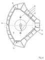
- FIG. 6 shows an airbag module for a three-spoke steering wheel shown in a bottom view.
- the generator carrier 10 forming lower area of the cover 5 is in this embodiment designed in one piece, by means of a hinge 15 pivotable and is secured with locking elements 14.
- FIG. 7 shows a bottom view of a further embodiment an airbag module for a three-spoke steering wheel.
- the lower area 10 of the cover is made up of three tabs 20 formed, and there are three threaded bolts 8 as Fastening means 8 are provided.
- FIG 8 finally shows an embodiment of an airbag module for a three-spoke steering wheel in which the generator carrier 10 formed by two overlapping tabs 20 becomes.
- Each of the tabs 20 is integral with the cover 5 formed and hinged to this via a hinge 15. Furthermore, both tabs 20 are secured by means of Locking elements 14 locked on the cover 5.
- FIG. 9 shows part of an airbag that has not yet been folded 6, into which a gas generator 7 is inserted is.
- the gas bag 6 has a slot 16 for inserting the Gas generator 7 and passages 17 for threading onto the threaded bolts 8 of the flange 9 of the gas generator 7.
- the Passages 17 preferably have a reinforced rim.
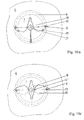
- FIG. 10a shows a preferred embodiment of the Airbag 6.
- the gas bag 6 has a cross-shaped slot 16 for the introduction of the gas generator 7 on.
- each of the slots 16 is formed Field 19 a passage 17 is provided in the one Threaded bolt 8 is threaded.
- connection method is generally suitable for Connection of gas bags to gas generators. It is about a particularly simple and at the same time safe procedure, with no retaining rings or other fastening devices required are. The only requirement is corresponding Threaded bolts, screws or other pins on the Gas generator through which the openings in the area of the slot can be threaded for the gas generator.
Landscapes
- Engineering & Computer Science (AREA)
- Mechanical Engineering (AREA)
- Air Bags (AREA)
Abstract
Description
- Figur 1:
- einen Querschnitt durch ein Lenkrad mit einem Airbagmodul;
- Figur 2:
- eine Unteransicht des Airbagmoduls aus Figur 1;
- Figur 3a:
- einen Querschnitt durch eine Abwandlung des Airbagmoduls aus Figur 1 und 2;
- Figur 3b:
- eine Unteransicht des Airbagmoduls aus Figur 3a;
- Figur 4a:
- einen Querschnitt durch ein Airbagmodul für ein Vierspeichenlenkrad;
- Figur 4b:
- eine Unteransicht des Airbagmoduls aus Figur 4a;
- Figur 5a:
- einen Querschnitt durch ein weiteres Airbagmodul für ein Vierspeichenlenkrad;
- Figur 5b:
- eine Unteransicht des Airbagmoduls aus Figur 5a;
- Figur 6:
- eine Unteransicht eines Airbagmoduls für ein Dreispeichenlenkrad;
- Figur 7:
- eine Unteransicht eines drei Laschen aufweisenden Airbagmoduls für ein Dreispeichenlenkrad;
- Figur 8:
- eine Unteransicht eines zwei überlappende Laschen aufweisenden Airbagmoduls;
- Figur 9:
- einen Gassack für ein erfindungsgemäßes Airbagmodul mit einer schlitzförmigen Öffnung, wobei in den Gassack ein Gasgenerator eingeführt ist;
- Figur 10a:
- einen Gassack mit einer kreuzschlitzförmigen Öffnung, durch die vier Felder in dem Gassack gebildet werden, wobei in den Gassack ein Gasgenerator eingeführt ist;
- Figur 10b:
- den Gassack aus Figur 10a, bei dem die ersten beiden Felder über Gewindebolzen eingefädelt sind;
- Figur 10c:
- den Gassack aus den Figuren 10a und 10b, bei dem die weiteren beiden Felder ebenfalls über die Gewindebolzen eingefädelt sind.
- 1.
- Lenkrad
- 2.
- Lenkradkranz
- 3.
- Lenkradnabe
- 4.
- Airbagmodul
- 5.
- Abdeckung
- 6.
- Gassack
- 7.
- Gasgenerator
- 8.
- Befestigungsmittel
- 9.
- Flansch
- 10.
- Generatorträger
- 11.
- Bohrungen
- 12.
- Zündkabel
- 13.
- Mutter
- 14.
- Rastelemente
- 15.
- Scharnier
- 16.
- Öffnung
- 17.
- Durchgang
- 18.
- Aussparung
- 19.
- Feld
- 20.
- Lasche
- 21.
- Anschluß für das Zündkabel
Claims (6)
- Gassack für ein Airbagmodul, mit Mitteln zur Anbindung des Gassackes an einen Gasgenerator, wobei der Gassack (6) eine schlitzförmige Öffnung (16) zum Einführen des Gasgenerators (7) aufweist, durch die mindestens zwei Felder (19) in dem Gassack (6) gebildet werden, und wobei in den Feldern (19) Durchgänge (17) vorgesehen sind, in die von dem Gasgenerator (7) abstehende Befestigungsmittel (8) einfädelbar sind,
dadurch gekennzeichnet, daß der Gassack (6) durch die schlitzförmige Öffnung (16) vollständig in den Gasgenerator (7) einführbar ist und daß die Durchgänge (17) derart über von dem eingeführten Gasgenerator (7) abstehende Befestigungsmittel (8) einfädelbar sind, daß die Felder (19) teilweise überlappen. - Gassack nach Anspruch 1, dadurch gekennzeichnet, daß die Felder (19) in dem Gassack (6) durch das Überlappen eine Aussparung (18) für einen Anschluß (21) eines Zündkabels (12) freigeben.
- Gassack nach Anspruch 1 oder 2, dadurch gekennzeichnet, daß die schlitzförmige Öffnung (16) eine gerade Anzahl Felder (19) bildet.
- Gassack nach einem der vorhergehenden Ansprüche, dadurch gekennzeichnet, daß die Durchgänge (17) gestanzte Löcher sind.
- Gassack nach einem der vorhergehenden Ansprüche, dadurch gekennzeichnet, daß die Durchgänge (17) einen verstärkten Rand aufweisen.
- Gassack nach einem der vorhergehenden Ansprüche, dadurch gekennzeichnet, daß zwei Befestigungsmittel (8) vorgesehen sind und die Öffnung (16) kreuzschlitzförmig ist.
Applications Claiming Priority (3)
| Application Number | Priority Date | Filing Date | Title |
|---|---|---|---|
| DE19905025A DE19905025C2 (de) | 1999-01-28 | 1999-01-28 | Airbagmodul |
| DE19905025 | 1999-01-28 | ||
| EP00910501A EP1144226B1 (de) | 1999-01-28 | 2000-01-21 | Airbagmodul |
Related Parent Applications (2)
| Application Number | Title | Priority Date | Filing Date |
|---|---|---|---|
| EP00910501A Division EP1144226B1 (de) | 1999-01-28 | 2000-01-21 | Airbagmodul |
| EP00910501.6 Division | 2000-01-21 |
Publications (3)
| Publication Number | Publication Date |
|---|---|
| EP1186484A2 true EP1186484A2 (de) | 2002-03-13 |
| EP1186484A3 EP1186484A3 (de) | 2002-05-08 |
| EP1186484B1 EP1186484B1 (de) | 2004-04-07 |
Family
ID=7896756
Family Applications (2)
| Application Number | Title | Priority Date | Filing Date |
|---|---|---|---|
| EP00910501A Expired - Lifetime EP1144226B1 (de) | 1999-01-28 | 2000-01-21 | Airbagmodul |
| EP01250405A Expired - Lifetime EP1186484B1 (de) | 1999-01-28 | 2000-01-21 | Gassack für ein Airbagmodul |
Family Applications Before (1)
| Application Number | Title | Priority Date | Filing Date |
|---|---|---|---|
| EP00910501A Expired - Lifetime EP1144226B1 (de) | 1999-01-28 | 2000-01-21 | Airbagmodul |
Country Status (6)
| Country | Link |
|---|---|
| US (1) | US6467799B2 (de) |
| EP (2) | EP1144226B1 (de) |
| JP (1) | JP2002535198A (de) |
| BR (1) | BR0007773A (de) |
| DE (3) | DE19905025C2 (de) |
| WO (1) | WO2000044592A2 (de) |
Cited By (1)
| Publication number | Priority date | Publication date | Assignee | Title |
|---|---|---|---|---|
| WO2021122685A1 (en) * | 2019-12-19 | 2021-06-24 | Autoliv Development Ab | Airbag; airbag assembly and method for assembling an airbag assembly |
Families Citing this family (16)
| Publication number | Priority date | Publication date | Assignee | Title |
|---|---|---|---|---|
| JP3942801B2 (ja) * | 2000-04-28 | 2007-07-11 | Ntn株式会社 | 回転角検出センサ |
| US6746042B2 (en) * | 2001-01-15 | 2004-06-08 | Trw Occupant Restraint Systems Gmbh & Co. Kg | Vehicle interior lining and method of producing a vehicle interior lining |
| DE20103892U1 (de) * | 2001-03-06 | 2001-07-12 | TRW Occupant Restraint Systems GmbH & Co. KG, 73553 Alfdorf | Fahrzeuginnenraumverkleidung |
| DE10136893B4 (de) * | 2001-07-25 | 2006-02-09 | Takata-Petri Ag | Airbagmodul |
| US6877765B2 (en) * | 2002-09-11 | 2005-04-12 | Autoliv Asp, Inc. | Load path control for inflatable airbag |
| DE20216754U1 (de) * | 2002-10-30 | 2003-03-20 | TRW Automotive Safety Systems GmbH & Co. KG, 63743 Aschaffenburg | Gassackmodul und Fahrzeuglenkrad mit einem Gassackmodul |
| JP2006001326A (ja) * | 2004-06-15 | 2006-01-05 | Takata Corp | エアバッグカバー、エアバッグ装置 |
| JP4687105B2 (ja) * | 2004-12-28 | 2011-05-25 | タカタ株式会社 | エアバッグ装置 |
| JP4627699B2 (ja) * | 2005-08-08 | 2011-02-09 | ダイセル化学工業株式会社 | エアバッグモジュール |
| DE102006057503A1 (de) * | 2006-12-06 | 2008-06-12 | GM Global Technology Operations, Inc., Detroit | Airbaganordnung |
| DE102010032175B4 (de) * | 2010-07-23 | 2015-02-26 | Autoliv Development Ab | Gassack |
| DE102010047090A1 (de) * | 2010-10-01 | 2012-04-05 | Autoliv Development Ab | Gassackmodul für ein Kraftfahrzeug |
| US8408583B2 (en) | 2010-11-09 | 2013-04-02 | Autoliv Asp, Inc. | Flangeless inflators and methods of making such inflators for use with inflatable airbag cushions |
| DE102011103323A1 (de) * | 2011-05-27 | 2012-11-29 | Autoliv Development Ab | Fahrerairbageinrichtung |
| US20130241183A1 (en) | 2012-03-15 | 2013-09-19 | Ramesh Keshavaraj | Coated airbag, method for making the same, and airbag module comprising the coated airbag |
| KR102832799B1 (ko) * | 2025-03-18 | 2025-07-11 | 주식회사 종합전기기술사사무소 | 건축용 소방시설 소화전 거치대 |
Family Cites Families (35)
| Publication number | Priority date | Publication date | Assignee | Title |
|---|---|---|---|---|
| US3752501A (en) | 1971-10-20 | 1973-08-14 | Ford Motor Co | Steering wheel inflatable cushion device |
| JPS51118231A (en) * | 1975-04-08 | 1976-10-18 | Toyota Motor Corp | Gas bag safety device |
| US5062664A (en) * | 1989-05-11 | 1991-11-05 | Allied-Signal Inc. | Air bag assembly |
| JPH0651458B2 (ja) * | 1989-10-23 | 1994-07-06 | 池田物産株式会社 | エアバッグ装置 |
| JPH03292236A (ja) * | 1990-04-10 | 1991-12-24 | Asahi Chem Ind Co Ltd | スリット型挿入孔付きエアーバッグ |
| DE9101099U1 (de) * | 1991-01-31 | 1992-06-04 | Autoliv-Kolb GmbH & Co, 8060 Dachau | Airbag |
| DE4235761C2 (de) | 1992-10-23 | 1995-06-08 | Daimler Benz Ag | Rückhaltesystem für Insassen von Kraftfahrzeugen |
| DE4313616A1 (de) * | 1993-04-26 | 1994-10-27 | Trw Repa Gmbh | Gassack-Rückhaltesystem für Fahrzeuge |
| DE9405143U1 (de) | 1994-03-25 | 1994-05-19 | Hs Tech & Design | Airbagvorrichtung |
| DE4417056B4 (de) * | 1994-05-14 | 2004-08-12 | Siemens Restraint Systems Gmbh | Airbag-Baueinheit |
| JP3456754B2 (ja) | 1994-06-14 | 2003-10-14 | 本田技研工業株式会社 | 車両用エアバッグの展開方法 |
| JP3316315B2 (ja) | 1994-09-06 | 2002-08-19 | タカタ株式会社 | 助手席用エアバッグ装置 |
| DE19505507C2 (de) * | 1995-02-10 | 1998-10-08 | Petri Ag Niederlassung Berlin | Gassack für einen Beifahrerairbag |
| WO1996038326A1 (en) * | 1995-05-31 | 1996-12-05 | Alliedsignal Inc. | Snap-on steering wheel with integral airbag housing |
| US5549326A (en) * | 1995-06-01 | 1996-08-27 | Trw Vehicle Safety Systems Inc. | Air bag |
| US5560648A (en) * | 1995-08-24 | 1996-10-01 | General Motors Corporation | Air bag deployment bias apparatus |
| DE19538594C2 (de) * | 1995-10-17 | 1997-08-14 | Autoliv Dev | Airbag-Anordnung |
| US5642900A (en) * | 1995-10-31 | 1997-07-01 | General Motors Corporation | Air bag attachment to module |
| DE29521369U1 (de) * | 1995-11-02 | 1997-01-23 | Petri Ag, 63743 Aschaffenburg | Gassack für ein Airbagmodul |
| JPH09142243A (ja) * | 1995-11-20 | 1997-06-03 | Honda Motor Co Ltd | 乗員保護用エアバッグ装置 |
| US5697637A (en) * | 1996-03-05 | 1997-12-16 | Trw Inc. | Vehicle occupant protection apparatus |
| DE19707997C2 (de) | 1997-02-27 | 2000-10-26 | Hs Tech & Design | Beifahrerairbagvorrichtung |
| US5632506A (en) * | 1996-06-14 | 1997-05-27 | Trw Vehicle Safety Systems Inc. | Vehicle occupant protection apparatus |
| DE19624371C2 (de) | 1996-06-19 | 2003-05-15 | Ebers & Mueller Fibrit | Kraftfahrzeugcockpit mit integriertem Airbag |
| DE29616916U1 (de) | 1996-09-27 | 1997-01-30 | Trw Occupant Restraint Systems Gmbh, 73551 Alfdorf | Gassack-Modul für ein Fahrzeuginsassen-Rückhaltesystem |
| DE29620298U1 (de) | 1996-11-21 | 1997-03-20 | Trw Occupant Restraint Systems Gmbh, 73551 Alfdorf | Gassack-Modul |
| JPH10166984A (ja) * | 1996-12-09 | 1998-06-23 | Ikeda Bussan Co Ltd | エアバッグ装置 |
| US5810390A (en) * | 1996-12-09 | 1998-09-22 | Morton International, Inc. | Module case for side impact airbag module |
| US5746447A (en) | 1997-01-21 | 1998-05-05 | Morton International, Inc. | Airbag module |
| DE29713111U1 (de) | 1997-07-23 | 1998-01-22 | Trw Repa Gmbh | Gassack-Rückhaltesystem für Fahrzeuginsassen |
| DE29713112U1 (de) | 1997-07-23 | 1998-01-22 | Trw Repa Gmbh | Gassack-Rückhaltesystem |
| US5806882A (en) * | 1997-11-20 | 1998-09-15 | Trw Vehicle Safety Systems Inc. | Vehicle occupant protection apparatus |
| DE29721643U1 (de) * | 1997-12-08 | 1998-04-02 | Trw Occupant Restraint Systems Gmbh, 73551 Alfdorf | Gassack-Modul für ein Fahrzeuginsassen-Rückhaltesystem |
| US6039341A (en) * | 1998-12-17 | 2000-03-21 | General Motors Corporation | Air bag module assembly |
| DE29910711U1 (de) * | 1999-06-18 | 1999-10-28 | TRW Automotive Safety Systems GmbH & Co.KG, 63743 Aschaffenburg | Baueinheit für ein Gassack-Modul und Gassack-Modul |
-
1999
- 1999-01-28 DE DE19905025A patent/DE19905025C2/de not_active Expired - Fee Related
-
2000
- 2000-01-21 JP JP2000595866A patent/JP2002535198A/ja active Pending
- 2000-01-21 EP EP00910501A patent/EP1144226B1/de not_active Expired - Lifetime
- 2000-01-21 DE DE50007016T patent/DE50007016D1/de not_active Expired - Fee Related
- 2000-01-21 DE DE50006001T patent/DE50006001D1/de not_active Expired - Fee Related
- 2000-01-21 BR BR0007773-9A patent/BR0007773A/pt not_active IP Right Cessation
- 2000-01-21 WO PCT/DE2000/000226 patent/WO2000044592A2/de not_active Ceased
- 2000-01-21 EP EP01250405A patent/EP1186484B1/de not_active Expired - Lifetime
-
2001
- 2001-07-27 US US09/915,399 patent/US6467799B2/en not_active Expired - Fee Related
Cited By (2)
| Publication number | Priority date | Publication date | Assignee | Title |
|---|---|---|---|---|
| WO2021122685A1 (en) * | 2019-12-19 | 2021-06-24 | Autoliv Development Ab | Airbag; airbag assembly and method for assembling an airbag assembly |
| US11872950B2 (en) | 2019-12-19 | 2024-01-16 | Autoliv Development Ab | Airbag, airbag assembly and method for assembling an airbag assembly |
Also Published As
| Publication number | Publication date |
|---|---|
| US20010052689A1 (en) | 2001-12-20 |
| EP1186484B1 (de) | 2004-04-07 |
| WO2000044592A2 (de) | 2000-08-03 |
| EP1186484A3 (de) | 2002-05-08 |
| BR0007773A (pt) | 2001-10-30 |
| DE50007016D1 (de) | 2004-08-12 |
| DE19905025A1 (de) | 2000-08-10 |
| DE19905025C2 (de) | 2003-11-13 |
| DE50006001D1 (de) | 2004-05-13 |
| JP2002535198A (ja) | 2002-10-22 |
| EP1144226B1 (de) | 2004-07-07 |
| WO2000044592A3 (de) | 2000-12-21 |
| EP1144226A2 (de) | 2001-10-17 |
| US6467799B2 (en) | 2002-10-22 |
Similar Documents
| Publication | Publication Date | Title |
|---|---|---|
| EP1186484B1 (de) | Gassack für ein Airbagmodul | |
| DE69604057T2 (de) | Airbagmodul | |
| DE29822768U1 (de) | Verkleidungsmodul | |
| DE19521937A1 (de) | Sicherheitsvorrichtung | |
| DE60008901T2 (de) | Montiermechanismus für ein aufblabares rückhaltesystem | |
| EP0945311A2 (de) | Aufprall-Schutzvorrichtung | |
| EP0802089A1 (de) | Baugruppe aus einem Lenkrad, einer Lenkwelle und einem Gassack-Modul | |
| DE69412671T2 (de) | Luftsack-Deckel | |
| DE10347205B4 (de) | Befestigung für einen Airbag | |
| DE19810277A1 (de) | Airbagvorrichtung | |
| EP0952044B1 (de) | Gassack-Modul für ein Fahrzeuginsassen- Rückhaltesystem und Verfahren zu seiner Herstellung | |
| EP2059417A1 (de) | Gassackabdeckung | |
| DE102004014742B4 (de) | Fahrzeug mit Vorhang-Airbag | |
| EP1147949B1 (de) | Gassackmodul | |
| EP0983913B1 (de) | Luftsack und Luftsackbefestigung | |
| DE19710063B4 (de) | Airbag mit Gaserzeuger | |
| DE69408200T2 (de) | Verfahren zum Befestigen von Luftsackkissen | |
| EP0876266A1 (de) | Vorrichtung zum schutz von insassen eines kfz | |
| DE10317335B4 (de) | Airbagvorrichtung | |
| EP4192710A1 (de) | Befestigungsvorrichtung für eine fahrzeuginnenverkleidung, anordnung einer befestigungsvorrichtung, gassackmodul und verfahren zum öffnen eines gassacks | |
| EP1060957B1 (de) | Baueinheit für ein Gassack-Modul und Gassack-Modul | |
| EP0849124B1 (de) | Fahrzeuglenkrad mit Airbagmodul | |
| DE4433014A1 (de) | Trägeranordnung zur Aufnahme und Halterung eines Gaskissens | |
| DE69705212T2 (de) | Gaskissen | |
| EP1122133A2 (de) | Aktiver Knieschutz mit Luftsack, Lastverteilerplatte und abreissbaren Verbindungselementen |
Legal Events
| Date | Code | Title | Description |
|---|---|---|---|
| PUAI | Public reference made under article 153(3) epc to a published international application that has entered the european phase |
Free format text: ORIGINAL CODE: 0009012 |
|
| AC | Divisional application: reference to earlier application |
Ref document number: 1144226 Country of ref document: EP |
|
| AK | Designated contracting states |
Kind code of ref document: A2 Designated state(s): AT BE CH CY DE DK ES FI FR GB GR IE IT LI LU MC NL PT SE |
|
| PUAL | Search report despatched |
Free format text: ORIGINAL CODE: 0009013 |
|
| AK | Designated contracting states |
Kind code of ref document: A3 Designated state(s): AT BE CH CY DE DK ES FI FR GB GR IE IT LI LU MC NL PT SE |
|
| 17P | Request for examination filed |
Effective date: 20020626 |
|
| GRAH | Despatch of communication of intention to grant a patent |
Free format text: ORIGINAL CODE: EPIDOS IGRA |
|
| AKX | Designation fees paid |
Designated state(s): DE ES FR GB SE |
|
| GRAH | Despatch of communication of intention to grant a patent |
Free format text: ORIGINAL CODE: EPIDOS IGRA |
|
| GRAA | (expected) grant |
Free format text: ORIGINAL CODE: 0009210 |
|
| AC | Divisional application: reference to earlier application |
Ref document number: 1144226 Country of ref document: EP Kind code of ref document: P |
|
| AK | Designated contracting states |
Kind code of ref document: B1 Designated state(s): DE ES FR GB SE |
|
| REG | Reference to a national code |
Ref country code: GB Ref legal event code: FG4D Free format text: NOT ENGLISH |
|
| REF | Corresponds to: |
Ref document number: 50006001 Country of ref document: DE Date of ref document: 20040513 Kind code of ref document: P |
|
| REG | Reference to a national code |
Ref country code: IE Ref legal event code: FG4D Free format text: GERMAN |
|
| PG25 | Lapsed in a contracting state [announced via postgrant information from national office to epo] |
Ref country code: SE Free format text: LAPSE BECAUSE OF FAILURE TO SUBMIT A TRANSLATION OF THE DESCRIPTION OR TO PAY THE FEE WITHIN THE PRESCRIBED TIME-LIMIT Effective date: 20040707 |
|
| PG25 | Lapsed in a contracting state [announced via postgrant information from national office to epo] |
Ref country code: ES Free format text: LAPSE BECAUSE OF FAILURE TO SUBMIT A TRANSLATION OF THE DESCRIPTION OR TO PAY THE FEE WITHIN THE PRESCRIBED TIME-LIMIT Effective date: 20040718 |
|
| GBT | Gb: translation of ep patent filed (gb section 77(6)(a)/1977) |
Effective date: 20040706 |
|
| REG | Reference to a national code |
Ref country code: IE Ref legal event code: FD4D |
|
| ET | Fr: translation filed | ||
| PLBE | No opposition filed within time limit |
Free format text: ORIGINAL CODE: 0009261 |
|
| STAA | Information on the status of an ep patent application or granted ep patent |
Free format text: STATUS: NO OPPOSITION FILED WITHIN TIME LIMIT |
|
| 26N | No opposition filed |
Effective date: 20050110 |
|
| PGFP | Annual fee paid to national office [announced via postgrant information from national office to epo] |
Ref country code: DE Payment date: 20090115 Year of fee payment: 10 |
|
| PGFP | Annual fee paid to national office [announced via postgrant information from national office to epo] |
Ref country code: GB Payment date: 20090121 Year of fee payment: 10 |
|
| PGFP | Annual fee paid to national office [announced via postgrant information from national office to epo] |
Ref country code: FR Payment date: 20090113 Year of fee payment: 10 |
|
| GBPC | Gb: european patent ceased through non-payment of renewal fee |
Effective date: 20100121 |
|
| REG | Reference to a national code |
Ref country code: FR Ref legal event code: ST Effective date: 20100930 |
|
| PG25 | Lapsed in a contracting state [announced via postgrant information from national office to epo] |
Ref country code: FR Free format text: LAPSE BECAUSE OF NON-PAYMENT OF DUE FEES Effective date: 20100201 |
|
| PG25 | Lapsed in a contracting state [announced via postgrant information from national office to epo] |
Ref country code: DE Free format text: LAPSE BECAUSE OF NON-PAYMENT OF DUE FEES Effective date: 20100803 |
|
| PG25 | Lapsed in a contracting state [announced via postgrant information from national office to epo] |
Ref country code: GB Free format text: LAPSE BECAUSE OF NON-PAYMENT OF DUE FEES Effective date: 20100121 |