EP1184740A2 - Tonerkassette und Bilderzeugungsvorrichtung - Google Patents
Tonerkassette und Bilderzeugungsvorrichtung Download PDFInfo
- Publication number
- EP1184740A2 EP1184740A2 EP01307213A EP01307213A EP1184740A2 EP 1184740 A2 EP1184740 A2 EP 1184740A2 EP 01307213 A EP01307213 A EP 01307213A EP 01307213 A EP01307213 A EP 01307213A EP 1184740 A2 EP1184740 A2 EP 1184740A2
- Authority
- EP
- European Patent Office
- Prior art keywords
- toner
- forming apparatus
- image forming
- remaining
- lever
- Prior art date
- Legal status (The legal status is an assumption and is not a legal conclusion. Google has not performed a legal analysis and makes no representation as to the accuracy of the status listed.)
- Granted
Links
Images


Classifications
-
- G—PHYSICS
- G03—PHOTOGRAPHY; CINEMATOGRAPHY; ANALOGOUS TECHNIQUES USING WAVES OTHER THAN OPTICAL WAVES; ELECTROGRAPHY; HOLOGRAPHY
- G03G—ELECTROGRAPHY; ELECTROPHOTOGRAPHY; MAGNETOGRAPHY
- G03G15/00—Apparatus for electrographic processes using a charge pattern
- G03G15/06—Apparatus for electrographic processes using a charge pattern for developing
- G03G15/08—Apparatus for electrographic processes using a charge pattern for developing using a solid developer, e.g. powder developer
- G03G15/0822—Arrangements for preparing, mixing, supplying or dispensing developer
- G03G15/0848—Arrangements for testing or measuring developer properties or quality, e.g. charge, size, flowability
- G03G15/0849—Detection or control means for the developer concentration
- G03G15/0855—Detection or control means for the developer concentration the concentration being measured by optical means
-
- G—PHYSICS
- G03—PHOTOGRAPHY; CINEMATOGRAPHY; ANALOGOUS TECHNIQUES USING WAVES OTHER THAN OPTICAL WAVES; ELECTROGRAPHY; HOLOGRAPHY
- G03G—ELECTROGRAPHY; ELECTROPHOTOGRAPHY; MAGNETOGRAPHY
- G03G15/00—Apparatus for electrographic processes using a charge pattern
- G03G15/06—Apparatus for electrographic processes using a charge pattern for developing
- G03G15/08—Apparatus for electrographic processes using a charge pattern for developing using a solid developer, e.g. powder developer
- G03G15/0822—Arrangements for preparing, mixing, supplying or dispensing developer
- G03G15/0848—Arrangements for testing or measuring developer properties or quality, e.g. charge, size, flowability
- G03G15/0856—Detection or control means for the developer level
- G03G15/086—Detection or control means for the developer level the level being measured by electro-magnetic means
-
- G—PHYSICS
- G03—PHOTOGRAPHY; CINEMATOGRAPHY; ANALOGOUS TECHNIQUES USING WAVES OTHER THAN OPTICAL WAVES; ELECTROGRAPHY; HOLOGRAPHY
- G03G—ELECTROGRAPHY; ELECTROPHOTOGRAPHY; MAGNETOGRAPHY
- G03G15/00—Apparatus for electrographic processes using a charge pattern
- G03G15/06—Apparatus for electrographic processes using a charge pattern for developing
- G03G15/08—Apparatus for electrographic processes using a charge pattern for developing using a solid developer, e.g. powder developer
- G03G15/0822—Arrangements for preparing, mixing, supplying or dispensing developer
- G03G15/0865—Arrangements for supplying new developer
- G03G15/0875—Arrangements for supplying new developer cartridges having a box like shape
-
- G—PHYSICS
- G03—PHOTOGRAPHY; CINEMATOGRAPHY; ANALOGOUS TECHNIQUES USING WAVES OTHER THAN OPTICAL WAVES; ELECTROGRAPHY; HOLOGRAPHY
- G03G—ELECTROGRAPHY; ELECTROPHOTOGRAPHY; MAGNETOGRAPHY
- G03G2215/00—Apparatus for electrophotographic processes
- G03G2215/08—Details of powder developing device not concerning the development directly
- G03G2215/0802—Arrangements for agitating or circulating developer material
- G03G2215/085—Stirring member in developer container
Definitions
- the present invention relates to an image forming apparatus such as an electrophotographic recording apparatus and a copying machine, and to a toner cartridge that is removably attached to an image forming apparatus.
- One conventional electrophotographic recording apparatus such as an electrophotographic color recording apparatus incorporates a plurality of image-forming apparatus for toner images of different colors, aligned in a direction in which a print medium travels.
- Each image-forming apparatus includes a photoconductive drum on which an electrostatic latent image is formed, and a developing unit by which the electrostatic latent image is developed with toner into a toner image.
- the developing unit includes a developing roller in pressure contact with the photoconductive drum and a toner-supplying roller which in turn is in contact with the developing roller.
- a toner cartridge holds toner therein and is attached to the developing unit.
- the toner cartridge has an opening through which the toner is discharged into the developing unit.
- the developing unit has a toner agitator that is located immediately below the opening of the toner cartridge and agitates the toner to prevent toner clumping.
- the image-forming apparatus has a toner detector that detects an amount of remaining toner.
- the aforementioned conventional toner cartridge discharges the toner therein over the toner agitator on the image-forming apparatus side. Therefore, the toner cartridge has to be mounted at a specific location relative to the image-forming apparatus. This is detrimental to miniaturization of the image-forming apparatus, particularly the dimension in the direction of travel of the print medium is difficult to be made smaller.
- An object of the present invention is to provide a toner cartridge having a remaining toner detecting mechanism that detects an amount of toner remaining in a toner chamber.
- An object of the present invention is to provide a toner cartridge that can detect an amount of toner remaining in a toner chamber and an image forming apparatus that can indicates to a user when the toner chamber in the chamber is nearing exhaustion.
- An object of the present invention is to provide a toner cartridge and an image-forming apparatus that can be miniaturized so that the dimension in the direction of travel of the print medium can be smaller.
- a toner cartridge is attached to an image forming apparatus.
- the toner cartridge has an opening (24) through which toner is discharged into a developing unit of the image forming apparatus (1).
- the toner cartridge includes:
- the coupling member (57) has a first end and a second end, the first end being connected to a remaining-toner detecting element (59);
- the agitating member (52) has an agitating element (52a) that agitates the toner in said toner chamber (33) and a transmitting element (52b) coupled to the second end of the coupling member (57), the transmitting element (52b) operating together with the agitating member (52) to transmit the motion of the agitating member (52) to the second end of the coupling member (57).
- the toner agitating mechanism (52, 52a, 52b, 57) includes: a crank shaft (52) that includes a first crank pin (52a) that agitates the toner and a second crank pin (52b) that is formed in the crank shaft (52), the crank shaft (52) being rotatably supported in the toner chamber (33); wherein the coupling member (57) has a first end rotatably coupled to the second crank pin (52b) and a second end slidably inserted in a guide path (58) provided above the toner chamber (33), the second end having a remaining-toner detecting element (59, 12A) provided thereto.
- the remaining-toner detecting element (59, 12A) may be a magnetic material (59).
- the remaining-toner detecting element (59, 12A) may be a permanent magnet (12A).
- a toner cartridge (17) and an image forming apparatus (Y, M, C, K) are combined such that the toner cartridge is detachably attached to the image forming apparatus.
- the toner cartridge (17) has an opening through which toner is discharged into a developing unit of the image forming apparatus.
- the toner cartridge (17) includes a first mechanism (52, 52a, 52b, 57, 12A, 59) having an agitating member (52) that is driven to agitate the toner in the toner chamber (33).
- the first mechanism (52, 52a, 52b, 57, 12A, 59) has an agitating member (52) that is driven to agitate the toner in a toner chamber (33).
- the first mechanism included remaining toner detecting mechanism (57, 52b, 12A, 59) that detects an amount of toner remaining in the toner chamber (33).
- the image forming apparatus (Y, M, C, K) include a second mechanism (14+15, 91, 59', 12) that detects an operation of the remaining-toner detecting mechanism (57, 52b, 12A, 59).
- the remaining toner detecting mechanism (57, 52b, 12A, 59)) includes:
- the second mechanism (14+15, 91, 12, 59') includes: a sensor lever (14) and a photosensor (15), the sensor lever (14) operating in response to a movement of the coupling member (57) to cause the photosensor (15) to selectively become ON and OFF.
- the sensor lever (14) has one end thereof to which a magnetic flux-sensitive element (59') is attached, the magnetic flux sensitive element (59') opposing the remaining-toner detecting element (12A) at the second end of the rod (57).
- the sensor lever (14) has one end thereof to which a magnet (12) is attached, the magnet (12) opposing the remaining-toner detecting element (59) at the second end of the coupling member (57).
- the sensor lever (14) includes a first lever (14a) and a second lever (14b) coupled to the first lever (14a) such that the second lever (14b) is pivotal relative to the first lever (14a) in an upward direction;
- the second mechanism (14+15, 91, 12, 59') includes a Hall effect element (91).
- the Hall effect element (91) is resiliently urged against a wall that separates the Hall effect element (91) from one end of the remaining toner detecting mechanism (52b, 57, 59, 12A).
- the toner cartridge is vertically movable between an up position and a down position when the image forming apparatus moves.
- the Hall effect element (91) is resiliently extended in a downward direction to detect the remaining-toner in the toner chamber (33).
- the Hall effect element (91) is resiliently retracted in the upward direction not to detect the remaining-toner in the toner chamber (33).
- the first mechanism (52, 52a, 52b, 57, 12A, 59) includes: a crank shaft (52) that includes a first crank pin (52a) that agitates the toner, the crank shaft (52) being rotatably supported in the toner chamber (33); wherein the remaining toner detecting mechanism (52b, 57, 59, 12A) comprises:
- the remaining-toner detecting element (59, 12A) may be a magnetic flux-sensitive element (59).
- the remaining-toner detecting element (59, 12A) may be a permanent magnet (12A).
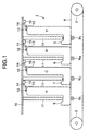
- Fig. 1 is a side view illustrating an electrophotographic recording apparatus according to a first embodiment.
- the electrophotographic color recording apparatus 1 includes a medium-transporting belt 4 that is entrained about drive rollers 2 and 3 and runs in the direction of travel of a print medium.
- a plurality of image forming apparatus 5 Y , 5 M , 5 C , and 5 K of the same configuration and corresponding transfer rollers 9 Y , 9 M , 9 C , and 9 K are aligned in the direction in which the medium transporting belt 4 runs.
- the image-forming apparatus 5 Y , 5 M , 5 C , and 5 K form yellow, magenta, cyan, and black images, respectively.
- Each of the image-forming apparatus has an exposing unit 11, a sensor lever 14, and a sensor 15, which are provided on a lid 10 of the electrophotographic color recording apparatus 1.
- the sensor lever 14 is pivotally supported on a pin 13.
- the sensor lever 14 has one end to which a permanent magnet 12 is attached and the other end that engages and disengages from the sensor 15 to actuate and de-actuate the sensor 15.
- the pin 13 is press-fitted into a bracket, not shown, on the lid 10.
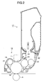
- Fig. 2 is a cross-sectional view of the image-forming apparatus 5 K for black image, by way of example.
- the image-forming apparatus 5 K includes a print process cartridge 16, and a toner cartridge 17 that is removably attached to the print process cartridge 16.
- the image-forming apparatus 5 Y , 5 M , and 5 C are of the same construction as the image-forming apparatus 5 K .
- the print process cartridge 16 has a photoconductive drum 18 on which an electrostatic latent image is formed.
- the photoconductive drum 18 extends in a direction transverse to the direction of travel of the print medium.
- Disposed around the photoconductive drum 18 are a charging roller 19, the exposing unit 11, a developing roller 20, the transfer roller 9, and a cleaning blade 21.
- the charging roller 19 charges the surface of the photoconductive drum 18 to a uniform potential.
- the exposing unit 11 illuminates the charged surface of the photoconductive drum 18 to form an electrostatic latent image thereon.
- the developing roller 20 develops the electrostatic latent image into a toner image.
- the transfer roller 9 causes the print medium to be charged to an opposite polarity to the toner image on the photoconductive drum 18, thereby allowing the toner image to be transferred onto the print medium.
- the cleaning blade 21 scrapes the residual toner from the photoconductive drum 18.
- the developing unit 22 includes the developing roller 20 with which a toner-supplying roller 23 is in pressure contact.
- the toner-supplying roller 23 supplies the toner, discharged from the toner cartridge 17 through the opening 24, to the developing roller 23.
- a blade 25 is in pressure contact with the developing roller 20 so as to form a thin layer of toner on the developing roller 20.
- Figs. 3 and 4 are exploded general perspective views of a toner cartridge according to the present invention.
- Fig. 5 is a fragmentary perspective view, showing a partial detail of the toner cartridge.
- Figs. 3 and 4 illustrate an outline of the construction of the toner cartridge 17 and the details are omitted.
- the detail of the operating knob 36 is not shown in Figs. 3 and 4 but in Fig. 15.
- the detail of the side plate is not shown in Figs. 3 and 4 but in Fig. 14.
- a cartridge case 26 of the toner cartridge 17 includes a housing 28 and a side plate 29.
- the housing 28 has a fresh toner chamber 33 and a waste toner chamber 34 defined side by side therein.
- the housing 28 is in one-piece construction with a side wall 27.
- the side plate 29 is fitted to the housing 28 to oppose the side wall 27.
- the side wall 27 has a hollow cylindrical boss 30 into which an operating knob 36 of the toner cartridge 17 is inserted, and a toner filling opening 31 through which the fresh toner is charged into the fresh toner chamber 33 of the toner cartridge 17.
- the toner filling opening 31 is closed with a cap 31a.
- the housing 28 has engagement openings 32 formed on the periphery thereof by which the side plate 29 is assembled to the housing 28.
- the fresh toner chamber 33 is formed with a plurality of openings 24 therein that are aligned in a longitudinal direction of the fresh toner chamber 33.
- the operating knob 36 is in one piece with a knob lever 37 and a shutter 38 of an arcuate shape.
- the shutter 38 closes the openings 24 when the operating knob 36 is rotated to a closing position and opens the opening 24 when the operating knob 36 is rotated to an opening position. Before the toner cartridge 17 is attached to the print process cartridge 16, the operating knob 36 is at the closing position.
- the knob 36 is formed with guide grooves 39 and 39a in its outer surface.
- the guide groove 39 receives later described projections 67a and 67b of the print process cartridge 16 when the toner cartridge 17 is attached into the print process cartridge 16.
- the knob 36 is also formed with a circumferential groove 40 (Fig. 4) in its circumferential surface.
- the groove 40 receives an annular sealing sponge 41a that prevents the fresh, unused toner from leaking through the gap between the operating knob 36 and the boss 30.
- Another sealing sponge 41b is attached to the outer circumferential surface of the shutter 38 surrounding the openings 24, thereby preventing the fresh, unused toner from leaking through the shutter 38 and the body case 28.
- the side plate 29 has an outer geometry fairly close to the cross section of the housing 28, and has projections 45 on its sides. When the side plate 29 is assembled to the housing 28, the projections 45 fit to the openings 32 of the housing 28.
- the side plate 29 is assembled to the housing 28 with a sealing sponge 47 sandwiched between the side plate 29 and the housing 28.
- the shape of the sealing sponge 47 is substantially the same as the outer geometry of the side plate 29.
- the side plate 29 has an opening 42 formed therein through which waste toner scraped from the photoconductive drum 18 is directed into the waste toner chamber 34.
- the side plate 29 also has two holes 43 and 44 (Fig. 3) formed therein that receive bosses 49 and 54 (Fig. 14), which will be described later.
- the holes 44 and 43 face the fresh toner chamber 33 and the waste toner chamber 34, respectively.
- the side plate 29 has a recess 46 formed therein that receives a projection 66 (Fig. 8) of the print process cartridge 16, which will be described later, to prevent the toner cartridge 17 from rotating relative to or disengaging from the print process cartridge 16.
- the housing 28 has an inner wall 35 that divides an inner space of the housing 28 into the fresh toner chamber 33 and the waste toner chamber 34.
- the inner wall 35 is positioned so that the fresh toner chamber 33 and the waste toner chamber 34 are aligned with each other in a direction transverse to the direction of travel of the print medium, i.e., in directions shown by arrows A and B of Fig. 4.
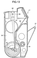
- Fig. 6 is a cross-sectional view, illustrating the detail of the waste toner chamber.
- a spiral shaft 48 extends horizontal in the waste toner chamber 34.
- the waste toner chamber 34 holds residual toner collected by the cleaning blade 21 from the photoconductive drum 18.
- the spiral shaft 48 is driven in rotation by a gear train 61.
- the tone exit 65 enters from the image forming apparatus to project into the waste toner chamber 34.
- the toner exit 65 directs waste toner into the waste toner chamber 34.
- Fig. 7 is a cross-sectional view, illustrating the detail of the fresh toner chamber.
- the fresh toner chamber 33 holds fresh, unused toner therein and houses the crank shaft 52 and the swingable member 53 that form the toner the toner agitating mechanism 51.
- the swingable member 53 is suspended from an upper portion of the fresh toner chamber 33 so that the swingable member 53 can swing easily.
- the swingable member 53 has a few narrow cutouts formed therein, which facilitate smooth swinging motion of the swingable member 53.
- a rod 57 is rotatably coupled to the short crank pin 52b and reciprocates vertically when the crank shaft 52 is rotated by the gear train 61.
- Fig. 8 is a perspective view, illustrating only an upper portion of the print process cartridge 16 that receives the toner cartridge 17.
- the upper portion of the print process cartridge 16 is generally U-shaped and has opposing upright side walls 63 and 64, and a bottom 62 between the side walls 63 and 64. Below the bottom 62 are disposed a print engine that includes the photoconductive drum 18, charging roller 19, developing roller, cleaning blade 21, and toner supplying roller 23 as shown in Fig. 3.
- the side wall 63 is formed with a waste toner exit 65 therein through which waste toner is directed into the waste toner chamber 34 of the toner cartridge 17.
- the side wall 63 also has the projection 66 formed near the toner exit 65.
- the side wall 64 has projections 67a and 67b that fit guide groove 39a and 39 formed in the knob 36 of Fig. 3 when the toner cartridge 17 is attached to the print process cartridge 16.
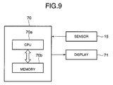
- Fig. 9 is a control block diagram for detecting an amount of fresh toner remaining in the toner cartridge 17.
- the controller 70 is connected to the sensor 15 and a display 71.
- the controller 70 includes a CPU 70a and a memory 70b.
- the memory 70b stores a reference value and a message.
- the reference value indicates a value at which the toner in the fresh toner chamber is nearing exhaustion.
- the message is displayed on the display 71 indicating to the user that the toner cartridge 17 needs to be replaced.
- Fig. 10 illustrates the loading of the toner cartridge into the print process cartridge.
- Figs. 11A and 11B illustrate the operation of the knob lever, Fig. 11A showing the knob lever position before it is rotated and Fig. 11B showing the knob lever position after it has completely rotated in a direction shown by arrow C.
- Fig. 12 is a side view showing the waste toner chamber and illustrating the operation of the waste toner chamber.
- the toner cartridge 17 is first tilted so that the toner exit 65 fits to the opening 42 formed in the side frame 29 of the toner cartridge 17.
- the operating knob 36 side is slowly lowered so that the toner cartridge 17 lies horizontal in the print process cartridge 16.
- the projection 66 is received in the recess 46 formed in the side plate 29 of Fig. 4, thereby positioning the toner cartridge 17 relative to the print process cartridge 16 and preventing the toner cartridge 17 from rotating or disengaging from the print process cartridge 16.
- the projections 67a and 67b on the print process cartridge 16 enter the guide groove 39a and 39 formed in the operating knob 36.
- the guide groove 39 receives the projections 67a and 67b therein completely, thereby firmly holding the operating knob 36 relative to the print process cartridge 16 and preventing the toner cartridge 17 from rotating or disengaging form the print process cartridge 16.
- the waste toner is directed into the waste toner chamber 34 through the toner exit 65.
- the gear train drives the spiral shaft 48 to rotate so that the rotating spiral shaft 48 makes the pile of toner grow from the near end (i.e., toner exit 65) of the waste toner chamber toward the far end (i.e., opening 42) of the chamber.
- Fig. 13 is a cross-section taken along line A-A of Fig. 5.
- the rod 57 has a lower end coupled to the short crank pin 52b and an upper end to which a magnetic material 59 is attached.
- the upper end portion is slidably inserted into a guide 58 provided on an upper wall of the body case 28.
- the guide 58 has an upper wall to which a film 60 is attached.
- Fig. 7 is a cross-sectional view illustrating the detail of the fresh toner chamber.
- a toner agitating mechanism 51 is provided in the fresh toner chamber 33.
- the toner agitating mechanism 51 is immediately over the openings 24 and is rotated to agitate the toner in the fresh toner chamber 33.
- the toner agitating mechanism 51 includes a crank shaft 52 and a resilient swingable member 53.
- the crank shaft 52 extends horizontal.
- the crank shaft 52 includes a long crank pin 52a and a short crank pin 52b.
- the long crank pin 52a extends substantially across the entire fresh toner chamber 33.
- the crank shaft 52 rotates, the long crank pin 52a engages the lower end portion of the resilient swingable member 53 to cause the member 53 to flex, and then disengages from the member 53 to allow the member 53 to resiliently swing back.
- the crank shaft 52 has one end rotatably received in a recess formed in a boss 54, which in turn is rotatably received in a supporting hole 44 (Fig. 3).
- the boss 54 has a projection 54a that engages the long crank pin 52a when the boss 54 rotates.
- the crank shaft 52 has the other end supported by the inner side of the operating knob 36.
- Fig. 14 is a perspective view illustrating the detail of a side plate.
- the bosses 49 and 54 are in mesh with the gear train 61 through, for example, resilient tongues. When the gear train 61 rotates, the bosses 49 and 54 are driven in rotation.
- the gear train 61 is coupled to a drive gear, not shown, of the print process cartridge 16. The drive gear drives the gear train 61 in rotation.
- the bosses 49 and 54 have projections 49a and 54a. When the projections 49a and 54a rotate, they abut the projection 48a of the spiral shaft 48 and the short crank pin 52b of the crank shaft 52, respectively, to drive the spiral shaft 48 and crank shaft 52 in rotation.
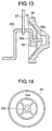
- Fig. 15 is a fragmentary view illustrating the relationship between an operating knob and the toner agitating mechanism.
- Fig. 16 is an elevation view of the operating knob.
- the operating knob 36 is formed with a generally cone-shaped recess 36a.
- the recess 36a receives a retainer 55 in the shape of a truncated cone.
- One end of the crank shaft 52 extends through a piece 56 and is rotatably received in the retainer 55.
- the short crank pin 52b fits into a recess 56a formed in the piece 56 such that the short crank pin 52b is clear of the retainer 55.
- the retainer 55 has a plurality of windows 55a formed therein such that toner entered the truncated cone shaped recess 36a in the operating knob 36 can be returned through holes 55a into the fresh toner chamber 33.
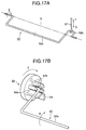
- Fig. 17A is a perspective view illustrating the overall structure of the crank shaft.
- Fig. 17B is a fragmentary perspective view of the boss that drives the crank shaft.
- crank shaft 52 rotates about a center line N when the boss 54 rotates.
- the crank 52 is heavier on the side of the long crank pin 52a than on the side of a short crank pin 52b. Therefore, the crank 52 will tend to be at rest with the long crank pin 52a at the bottom and the short crank pin 52b at the top if the crank 52 is not left free to rotate.
- the short crank pin 52b is coupled to a rod 57, which is rotatable about the short crank pin 52b.
- the rod 57 reciprocates vertically in directions shown by arrows F and G.
- the crank 52 is rotatably held in the boss 54 by circumferentially aligned pieces 54b.
- the piece 54a abuts the long crank pin 52a of the crank 52, causing the crank 52 to rotate in the E direction together with the boss 54.
- the crank 52 quickly rotates by 180 degrees so that the long crank pin 52a drops to its lowest position if little or no fresh toner is left in the fresh toner chamber 33.
- a piece 54c serves as a stopper against which the long crank pin 52a abuts.
- the waste toner falls in the waste toner chamber 34 and piles up to the height of the spiral shaft 48. Then, the rotating spiral shaft 48 makes the pile of toner grow from the near end (i.e., toner exit 65) of the waste toner chamber toward the far end (i.e., opening 42) of the chamber.
- crank shaft 52 is rotating in the fresh toner chamber 33 and the CPU 70a of the controller 70 detects the remaining toner in the toner cartridge 17 by means of the sensor 15.
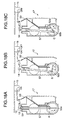
- Figs. 18A-18G illustrate the operation of the agitating mechanism.
- Fig. 18 H illustrates the relationship between the ON time of the sensor 15 and the position of the short crank pin when the remaining toner in the toner cartridge is still sufficient.
- Fig. 18I illustrates the relationship between the ON time of the sensor 15 and the position of the short crank pin when the remaining toner in the toner cartridge is still sufficient.
- crank shaft 52 is heavier on the side of the long crank pin 52a than on the side of the short crank pin 52b, so that the long crank pin 52a tends to drop to the bottom of the fresh toner chamber 33 at all times.
- the agitating mechanism operates as follows:
- the long crank pin 52a When the long crank pin 52a reaches position C as shown in Fig. 18C, the long crank pin 52a engages the swingable member 53 to cause the swingable member 53 to flex. As the long crank pin 52a is further rotated, the long crank pin 52a causes the swingable member 53 to further flex, while also sliding on the swingable member 53. The long crank pin 52a continues to slide on the swingable member 53 and reaches the free end of the swingable member 53 as shown in Fig. 18D where the swingable member 53 has swung with a maximum amplitude.
- the agitating mechanism operates subsequently as follows:
- the long crank pin 52a moves out of abutting engagement with the swingable member 53 and the swingable member 53 resiliently swings in a direction shown by arrow J back to its original position.
- the long crank pin 52a cannot fall to its lowest position but rests on the pile of toner as shown in Fig. 18E.
- the long crank pin 52a gradually enters the pile of toner as the long crank pin 52a is further rotated by the projection 54a.
- the agitating mechanism operates as follows:
- the ON time of the sensor 15 is longer when the remaining toner in the fresh toner chamber 33 is still sufficient than when the remaining toner in the fresh toner chamber 33 is nearing exhaustion, i.e., t L > t F .
- the CPU 70a incorporates a built-in timer that counts the ON time t of the sensor 15.
- the CPU 70a compares the output of the timer with a reference to determine whether the output exceeds the threshold value.
- the reference value is selected to be, for example, T/2 where T is the time required for one complete rotation of the boss 54. If the ON time of the sensor 15 exceeds the reference value, the CPU 70a reads a "message for replacement of toner cartridge" from the memory 70b and displays the message to indicate to the user that the toner cartridge 17 has only a small amount of toner left therein.
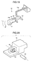
- a second embodiment differs from the first embodiment in that a sensor lever includes a first lever and a second lever coupled to the first lever through a shaft such that the first lever is pivotal about the shaft.
- Fig. 19 is a perspective view of the sensor lever.
- Fig. 20 is a fragmentary perspective view of the second lever of the sensor lever.
- the sensor lever 14 includes a first lever 14a and a second lever 14b.
- the first and second levers 14a and 14b are coupled through a shaft 80.
- a torsion spring 84 (Fig. 20) is loaded between the first and second lever 14a and 14b so that the second lever 14b is urged by a torsion spring 84 in a direction M opposite to the direction shown by arrow L.
- the second lever 14b has a recess 81 formed therein.
- the first lever 14a has a stepped portion 83 and a projection 82 over which the recess 81 of the second lever 14b fits such that the second lever 14b is pivotal about the shaft 80.
- the torsion spring 84 is loaded about the shaft 80 so that the second lever 14b is urged in a direction shown by arrow M.
- the image forming apparatus 5 K for black is moved to its down position where the image forming apparatus is close to the medium transporting belt 4.
- the image forming apparatus 5 Y , 5 M , and 5 C , for yellow, magenta, and cyan are moved to their up positions where the image forming apparatus 5 Y , 5 M , 5 C , and 5 K are away from the medium transporting belt 4.
- the boss 54 is not driven in rotation, i.e., the remaining toner in the fresh toner chamber is not detected.
- the gap between the toner cartridge 17 and the sensor lever 14 should be selected taking into account the vertical stroke of the image forming apparatus when they move between the down position and up position.
- the top end of the image forming apparatus 5 abuts the second lever 14b to push the second lever 14b upward, so that the second lever 14b pivots in the direction shown by arrow L.
- This operation of the second lever allows the sensor lever may remain mounted at the same position as the first embodiment while still providing proper toner detecting function when the image forming apparatus is at the down position.
- the first lever 14a that drives the sensor to become ON and OFF is pivotal relative to the second lever 14b.
- the second lever 14b yieldingly pivots about the shaft 80. This construction minimizes the space that accommodates the image forming apparatus in the printer.
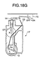
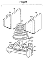
- a third embodiment differs from the first embodiment in that the sensor takes the form of a Hall effect element and the sensor lever is not used.
- Fig. 21 is an exploded perspective view of a sensor mechanism according to the third embodiment.
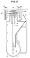
- Fig. 22 is a side view illustrating a remaining-toner detecting mechanism according to the third embodiment when the image forming apparatus is at the down position.
- FIG. 21 and 22 there are provided two vertical walls 95 and 96 that have guide grooves 95a and 96a formed therein, respectively.
- the walls 95 and 96 are fixed to the lid 10 of the image forming apparatus.
- a holder 94 has guide projections 94a and 94b formed on its opposing vertical sides.
- the guide projections 94a and 94b loosely fit into the guide grooves 95a and 96a, respectively, so that the holder 94 is vertically slidable relative to the walls 95 and 96.
- the holder 94 holds a board 93 that carries a Hall effect element 91 secured in a hole 92.
- the holder 94 is urged by a coil spring 97 against the top of the toner cartridge 17.
- the spring 97 has a top end secured to the inner side of the lid 10 of the electrophotographic recording apparatus 1 and a bottom end secured to the sensor holder 94.
- the holder 94 is resiliently urged by the spring 97 against a top wall of the toner cartridge 17 that separates the Hall effect element 91 from one end of the rod 57. It is assumed that unlike the first embodiment, the image forming apparatus is required to move up and down relative to the medium transporting belt 4.
- the toner cartridge 17 vertically moves when the image forming apparatus 1 is moved between an up position and a down position.
- the holder 94 is resiliently moved downward.
- the holder 94 is resiliently moved upward.
- the permanent magnet 12 moves away from the Hall effect element 91 so that the Hall effect element 91 becomes OFF.
- the permanent magnet 12 can be accurately positioned relative to the Hall effect element 91.
- the ON time of the sensor will become longer as the remaining toner is nearing exhaustion.
- a reference value may be set equal to the length of the ON time of the sensor immediately after the toner cartridge 17 has been replaced by a new, unused one.
- the CPU 70a may display a message that prompts replacement of toner cartridge.
Landscapes
- Physics & Mathematics (AREA)
- General Physics & Mathematics (AREA)
- Dry Development In Electrophotography (AREA)
- Control Or Security For Electrophotography (AREA)
Applications Claiming Priority (2)
| Application Number | Priority Date | Filing Date | Title |
|---|---|---|---|
| JP2000257400 | 2000-08-28 | ||
| JP2000257400A JP3685694B2 (ja) | 2000-08-28 | 2000-08-28 | トナーカートリッジと画像形成装置 |
Publications (3)
| Publication Number | Publication Date |
|---|---|
| EP1184740A2 true EP1184740A2 (de) | 2002-03-06 |
| EP1184740A3 EP1184740A3 (de) | 2004-02-11 |
| EP1184740B1 EP1184740B1 (de) | 2007-11-28 |
Family
ID=18745863
Family Applications (1)
| Application Number | Title | Priority Date | Filing Date |
|---|---|---|---|
| EP01307213A Expired - Lifetime EP1184740B1 (de) | 2000-08-28 | 2001-08-24 | Tonerkassette und Bilderzeugungsvorrichtung |
Country Status (4)
| Country | Link |
|---|---|
| US (1) | US6546213B2 (de) |
| EP (1) | EP1184740B1 (de) |
| JP (1) | JP3685694B2 (de) |
| DE (1) | DE60131611T2 (de) |
Cited By (5)
| Publication number | Priority date | Publication date | Assignee | Title |
|---|---|---|---|---|
| RU2460109C2 (ru) * | 2007-03-27 | 2012-08-27 | Самсунг Электроникс Ко., Лтд. | Проявочный узел и устройство для формирования изображения, содержащее такой узел |
| US20130004208A1 (en) * | 2011-07-01 | 2013-01-03 | Oki Data Corporation | Developer holding apparatus, developing unit that incorporates the developer holding apparatus, and image forming apparatus that employs the developer holding apparatus |
| CN103454878A (zh) * | 2012-04-19 | 2013-12-18 | 莱克斯马克国际公司 | 图像形成装置的可更换单元的调色剂搅拌系统 |
| CN108369395A (zh) * | 2015-12-11 | 2018-08-03 | 株式会社村田制作所 | 墨粉瓶 |
| US10983477B2 (en) | 2016-04-13 | 2021-04-20 | Ninestar Corporation | Process cartridge |
Families Citing this family (37)
| Publication number | Priority date | Publication date | Assignee | Title |
|---|---|---|---|---|
| JP3893259B2 (ja) * | 2001-08-07 | 2007-03-14 | 株式会社沖データ | トナーカートリッジと画像形成装置 |
| JP4096783B2 (ja) * | 2003-03-28 | 2008-06-04 | ブラザー工業株式会社 | 現像装置および画像形成装置 |
| JP3945437B2 (ja) * | 2003-03-28 | 2007-07-18 | ブラザー工業株式会社 | 画像形成装置 |
| US7171132B2 (en) | 2003-06-27 | 2007-01-30 | Oki Data Corporation | Image forming apparatus having position controller |
| US7187876B2 (en) | 2003-11-27 | 2007-03-06 | Oki Data Corporation | Image forming apparatus with mechanism to control toner replenishment |
| US7136608B2 (en) * | 2003-12-19 | 2006-11-14 | Steven Miller | Removable toner cartridge universal adapter |
| JP4414790B2 (ja) | 2004-03-08 | 2010-02-10 | 株式会社沖データ | 現像装置 |
| US7437095B2 (en) | 2004-06-04 | 2008-10-14 | Oki Data Corporation | Image forming apparatus and toner cartridge |
| GB2421320A (en) * | 2004-12-16 | 2006-06-21 | Kevin Coppard | Toner agitator or shaker |
| US7231153B2 (en) * | 2005-01-13 | 2007-06-12 | Xerox Corporation | Systems and methods for monitoring replaceable units |
| US7076180B1 (en) * | 2005-05-24 | 2006-07-11 | General Plastic Industrial Co., Ltd. | Toner cartridge |
| US20090148194A1 (en) * | 2007-12-05 | 2009-06-11 | Master Ink Company, Ltd. | Toner cartridge |
| JP5463719B2 (ja) | 2009-04-16 | 2014-04-09 | 富士ゼロックス株式会社 | 画像形成装置 |
| USD626172S1 (en) * | 2010-02-26 | 2010-10-26 | Katun Corporation | Toner container |
| JP5289390B2 (ja) * | 2010-07-07 | 2013-09-11 | 株式会社沖データ | 現像剤収容器、画像形成ユニット、及び画像形成装置 |
| US8867966B2 (en) * | 2011-12-30 | 2014-10-21 | Lexmark International, Inc. | Toner cartridge for use in an image forming device |
| JP5683520B2 (ja) * | 2012-03-28 | 2015-03-11 | 株式会社沖データ | 現像剤収容体、現像剤回収装置、および画像形成装置 |
| JP5638035B2 (ja) | 2012-06-28 | 2014-12-10 | 株式会社沖データ | 現像剤収容体、現像装置及び画像形成装置 |
| US9069286B2 (en) | 2012-12-18 | 2015-06-30 | Lexmark International, Inc. | Rotational sensing for a replaceable unit of an image forming device |
| US9031424B2 (en) | 2012-12-18 | 2015-05-12 | Lexmark International, Inc. | Systems and methods for measuring a particulate material |
| US9128443B2 (en) | 2012-12-18 | 2015-09-08 | Lexmark International, Inc. | Toner level sensing for replaceable unit of an image forming device |
| US8989611B2 (en) | 2012-12-18 | 2015-03-24 | Lexmark International, Inc. | Replaceable unit for an image forming device having a falling paddle for toner level sensing |
| US9152080B2 (en) | 2012-12-18 | 2015-10-06 | Lexmark International, Inc. | Replaceable unit for an image forming device having a toner agitator that includes a magnet for rotational sensing |
| US9104134B2 (en) | 2012-12-18 | 2015-08-11 | Lexmark International, Inc. | Toner level sensing for replaceable unit of an image forming device |
| CN106154794B (zh) * | 2015-05-13 | 2019-08-06 | 纳思达股份有限公司 | 一种处理盒 |
| US9128444B1 (en) | 2014-04-16 | 2015-09-08 | Lexmark International, Inc. | Toner level sensing for a replaceable unit of an image forming device using pulse width patterns from a magnetic sensor |
| US9389582B2 (en) | 2014-06-02 | 2016-07-12 | Lexmark International, Inc. | Replaceable unit for an image forming device having magnets of varying angular offset for toner level sensing |
| US9519243B2 (en) | 2014-06-02 | 2016-12-13 | Lexmark International, Inc. | Replaceable unit for an image forming device having magnets of varying angular offset for toner level sensing |
| US9335656B2 (en) | 2014-06-02 | 2016-05-10 | Lexmark International, Inc. | Toner level sensing using rotatable magnets having varying angular offset |
| US9280084B1 (en) | 2015-02-25 | 2016-03-08 | Lexmark International, Inc. | Magnetic sensor positioning by a replaceable unit of an electrophotographic image forming device |
| US9291989B1 (en) | 2015-02-25 | 2016-03-22 | Lexmark International, Inc. | Replaceable unit for an electrophotographic image forming device having an engagement member for positioning a magnetic sensor |
| JP7059543B2 (ja) * | 2017-09-15 | 2022-04-26 | 京セラドキュメントソリューションズ株式会社 | 画像形成装置 |
| US10474060B1 (en) | 2018-07-05 | 2019-11-12 | Lexmark International, Inc. | Toner level sensing using rotatable magnets having varying angular offset |
| US10429765B1 (en) | 2018-07-05 | 2019-10-01 | Lexmark International, Inc. | Toner container for an image forming device having magnets of varying angular offset for toner level sensing |
| US10345736B1 (en) | 2018-07-20 | 2019-07-09 | Lexmark International, Inc. | Toner level detection measuring a radius of a rotatable magnet |
| US10451997B1 (en) | 2018-07-20 | 2019-10-22 | Lexmark International, Inc. | Toner level detection measuring an orientation of a rotatable magnet having a varying orientation relative to a pivot axis |
| US10451998B1 (en) | 2018-07-20 | 2019-10-22 | Lexmark International, Inc. | Toner level detection measuring an orientation of a rotatable magnet having a varying radius |
Family Cites Families (13)
| Publication number | Priority date | Publication date | Assignee | Title |
|---|---|---|---|---|
| JPH02236574A (ja) * | 1989-03-10 | 1990-09-19 | Canon Inc | 画像形成装置 |
| US5068691B1 (en) * | 1989-06-01 | 1995-01-24 | Fujitsu Ltd | Developing device with a controllable pressure release for the developing roller |
| JPH0331878A (ja) * | 1989-06-28 | 1991-02-12 | Nec Corp | プロセスカートリッジ |
| JP2837973B2 (ja) * | 1991-07-04 | 1998-12-16 | 沖電気工業株式会社 | トナー残量検知機構 |
| JPH05127520A (ja) * | 1991-11-08 | 1993-05-25 | Fujitsu Ltd | 現像剤の片寄り解消装置 |
| JPH05232806A (ja) * | 1992-02-24 | 1993-09-10 | Murata Mach Ltd | 画像形成装置 |
| JP3009794B2 (ja) * | 1992-11-30 | 2000-02-14 | 三田工業株式会社 | 画像形成装置 |
| JPH06266229A (ja) * | 1993-03-17 | 1994-09-22 | Minolta Camera Co Ltd | トナー補給装置 |
| US5436704A (en) * | 1993-05-31 | 1995-07-25 | Samsung Electronics Co., Ltd. | Device for sensing the amount of residual toner of developing apparatus |
| JPH0844182A (ja) * | 1994-07-28 | 1996-02-16 | Ricoh Co Ltd | 現像装置 |
| JP3224490B2 (ja) * | 1995-03-31 | 2001-10-29 | キヤノン株式会社 | 粉体貯留装置及び画像形成装置 |
| JPH1184850A (ja) * | 1997-07-07 | 1999-03-30 | Canon Inc | 画像形成装置、プロセスカートリッジ及び現像装置 |
| JP3373139B2 (ja) * | 1997-07-24 | 2003-02-04 | 株式会社沖データ | トナ−残量検知機構 |
-
2000
- 2000-08-28 JP JP2000257400A patent/JP3685694B2/ja not_active Expired - Lifetime
-
2001
- 2001-08-24 US US09/935,764 patent/US6546213B2/en not_active Expired - Lifetime
- 2001-08-24 DE DE60131611T patent/DE60131611T2/de not_active Expired - Lifetime
- 2001-08-24 EP EP01307213A patent/EP1184740B1/de not_active Expired - Lifetime
Cited By (6)
| Publication number | Priority date | Publication date | Assignee | Title |
|---|---|---|---|---|
| RU2460109C2 (ru) * | 2007-03-27 | 2012-08-27 | Самсунг Электроникс Ко., Лтд. | Проявочный узел и устройство для формирования изображения, содержащее такой узел |
| US20130004208A1 (en) * | 2011-07-01 | 2013-01-03 | Oki Data Corporation | Developer holding apparatus, developing unit that incorporates the developer holding apparatus, and image forming apparatus that employs the developer holding apparatus |
| US8918026B2 (en) * | 2011-07-01 | 2014-12-23 | Oki Data Corporation | Developer holding apparatus, developing unit that incorporates the developer holding apparatus, and image forming apparatus that employs the developer holding apparatus |
| CN103454878A (zh) * | 2012-04-19 | 2013-12-18 | 莱克斯马克国际公司 | 图像形成装置的可更换单元的调色剂搅拌系统 |
| CN108369395A (zh) * | 2015-12-11 | 2018-08-03 | 株式会社村田制作所 | 墨粉瓶 |
| US10983477B2 (en) | 2016-04-13 | 2021-04-20 | Ninestar Corporation | Process cartridge |
Also Published As
| Publication number | Publication date |
|---|---|
| US20020028081A1 (en) | 2002-03-07 |
| JP3685694B2 (ja) | 2005-08-24 |
| JP2002072657A (ja) | 2002-03-12 |
| US6546213B2 (en) | 2003-04-08 |
| EP1184740A3 (de) | 2004-02-11 |
| DE60131611T2 (de) | 2008-10-23 |
| EP1184740B1 (de) | 2007-11-28 |
| DE60131611D1 (de) | 2008-01-10 |
Similar Documents
| Publication | Publication Date | Title |
|---|---|---|
| US6546213B2 (en) | Toner cartridge and image forming apparatus | |
| JP3893259B2 (ja) | トナーカートリッジと画像形成装置 | |
| US6091912A (en) | Tower supplying device and image forming apparatus using same toner supplying device | |
| US7187876B2 (en) | Image forming apparatus with mechanism to control toner replenishment | |
| US7840165B2 (en) | Toner replenishing apparatus, image forming apparatus, and color image forming apparatus | |
| JP2009036921A (ja) | 画像形成装置 | |
| US8224225B2 (en) | Waste powder recovery container, connecting structure to waste powder recovery container, developing device, and image forming apparatus | |
| JP7190106B2 (ja) | 粉体収納容器、プロセスカートリッジ、及び、画像形成装置 | |
| JPH04372968A (ja) | 画像形成装置 | |
| JP2014062993A (ja) | 現像剤収納ユニット、現像装置、プロセスカートリッジ及び電子写真画像形成装置 | |
| JPH04208946A (ja) | 画像形成装置 | |
| JPH11143196A (ja) | 画像形成装置 | |
| JP4028944B2 (ja) | 二成分現像装置及び画像形成装置 | |
| JP2005241865A (ja) | トナー補給装置及びこれを用いた現像装置、画像形成装置 | |
| GB2302960A (en) | Developing apparatus | |
| JP2552869B2 (ja) | 複写機の現像装置 | |
| JP5648598B2 (ja) | 画像形成装置およびトナーボトル | |
| JPH08305149A (ja) | トナーカートリッジ、プロセスカートリッジ、現像装置及び画像形成装置 | |
| JP3303607B2 (ja) | 回転型現像装置 | |
| JP3987167B2 (ja) | 画像形成装置 | |
| JPH11295975A (ja) | 画像形成装置 | |
| JP2861540B2 (ja) | 現像装置 | |
| JPH09297462A (ja) | 画像形成装置 | |
| US7565090B2 (en) | Method of refilling developer cartridge, developer cartridge, and image forming apparatus | |
| JP6897138B2 (ja) | 廃トナー収容容器およびこれを備える画像形成装置 |
Legal Events
| Date | Code | Title | Description |
|---|---|---|---|
| PUAI | Public reference made under article 153(3) epc to a published international application that has entered the european phase |
Free format text: ORIGINAL CODE: 0009012 |
|
| AK | Designated contracting states |
Kind code of ref document: A2 Designated state(s): AT BE CH CY DE DK ES FI FR GB GR IE IT LI LU MC NL PT SE TR |
|
| AX | Request for extension of the european patent |
Free format text: AL;LT;LV;MK;RO;SI |
|
| PUAL | Search report despatched |
Free format text: ORIGINAL CODE: 0009013 |
|
| AK | Designated contracting states |
Kind code of ref document: A3 Designated state(s): AT BE CH CY DE DK ES FI FR GB GR IE IT LI LU MC NL PT SE TR |
|
| AX | Request for extension of the european patent |
Extension state: AL LT LV MK RO SI |
|
| 17P | Request for examination filed |
Effective date: 20040617 |
|
| AKX | Designation fees paid |
Designated state(s): DE FR GB |
|
| 17Q | First examination report despatched |
Effective date: 20041019 |
|
| GRAP | Despatch of communication of intention to grant a patent |
Free format text: ORIGINAL CODE: EPIDOSNIGR1 |
|
| GRAS | Grant fee paid |
Free format text: ORIGINAL CODE: EPIDOSNIGR3 |
|
| GRAA | (expected) grant |
Free format text: ORIGINAL CODE: 0009210 |
|
| AK | Designated contracting states |
Kind code of ref document: B1 Designated state(s): DE FR GB |
|
| REF | Corresponds to: |
Ref document number: 60131611 Country of ref document: DE Date of ref document: 20080110 Kind code of ref document: P |
|
| ET | Fr: translation filed | ||
| PLBE | No opposition filed within time limit |
Free format text: ORIGINAL CODE: 0009261 |
|
| STAA | Information on the status of an ep patent application or granted ep patent |
Free format text: STATUS: NO OPPOSITION FILED WITHIN TIME LIMIT |
|
| 26N | No opposition filed |
Effective date: 20080829 |
|
| REG | Reference to a national code |
Ref country code: FR Ref legal event code: PLFP Year of fee payment: 16 |
|
| REG | Reference to a national code |
Ref country code: FR Ref legal event code: PLFP Year of fee payment: 17 |
|
| REG | Reference to a national code |
Ref country code: FR Ref legal event code: PLFP Year of fee payment: 18 |
|
| PGFP | Annual fee paid to national office [announced via postgrant information from national office to epo] |
Ref country code: GB Payment date: 20200813 Year of fee payment: 20 Ref country code: FR Payment date: 20200715 Year of fee payment: 20 Ref country code: DE Payment date: 20200812 Year of fee payment: 20 |
|
| REG | Reference to a national code |
Ref country code: DE Ref legal event code: R071 Ref document number: 60131611 Country of ref document: DE |
|
| REG | Reference to a national code |
Ref country code: GB Ref legal event code: PE20 Expiry date: 20210823 |
|
| PG25 | Lapsed in a contracting state [announced via postgrant information from national office to epo] |
Ref country code: GB Free format text: LAPSE BECAUSE OF EXPIRATION OF PROTECTION Effective date: 20210823 |