EP1180575A2 - Vorsatztür mit Schliessmechanismus - Google Patents
Vorsatztür mit Schliessmechanismus Download PDFInfo
- Publication number
- EP1180575A2 EP1180575A2 EP01119447A EP01119447A EP1180575A2 EP 1180575 A2 EP1180575 A2 EP 1180575A2 EP 01119447 A EP01119447 A EP 01119447A EP 01119447 A EP01119447 A EP 01119447A EP 1180575 A2 EP1180575 A2 EP 1180575A2
- Authority
- EP
- European Patent Office
- Prior art keywords
- front door
- frame
- torsion bar
- door according
- door
- Prior art date
- Legal status (The legal status is an assumption and is not a legal conclusion. Google has not performed a legal analysis and makes no representation as to the accuracy of the status listed.)
- Granted
Links
Images

Classifications
-
- E—FIXED CONSTRUCTIONS
- E05—LOCKS; KEYS; WINDOW OR DOOR FITTINGS; SAFES
- E05F—DEVICES FOR MOVING WINGS INTO OPEN OR CLOSED POSITION; CHECKS FOR WINGS; WING FITTINGS NOT OTHERWISE PROVIDED FOR, CONCERNED WITH THE FUNCTIONING OF THE WING
- E05F1/00—Closers or openers for wings, not otherwise provided for in this subclass
- E05F1/08—Closers or openers for wings, not otherwise provided for in this subclass spring-actuated, e.g. for horizontally sliding wings
- E05F1/10—Closers or openers for wings, not otherwise provided for in this subclass spring-actuated, e.g. for horizontally sliding wings for swinging wings, e.g. counterbalance
- E05F1/1033—Closers or openers for wings, not otherwise provided for in this subclass spring-actuated, e.g. for horizontally sliding wings for swinging wings, e.g. counterbalance with a torsion bar
-
- E—FIXED CONSTRUCTIONS
- E05—LOCKS; KEYS; WINDOW OR DOOR FITTINGS; SAFES
- E05F—DEVICES FOR MOVING WINGS INTO OPEN OR CLOSED POSITION; CHECKS FOR WINGS; WING FITTINGS NOT OTHERWISE PROVIDED FOR, CONCERNED WITH THE FUNCTIONING OF THE WING
- E05F1/00—Closers or openers for wings, not otherwise provided for in this subclass
- E05F1/08—Closers or openers for wings, not otherwise provided for in this subclass spring-actuated, e.g. for horizontally sliding wings
- E05F1/10—Closers or openers for wings, not otherwise provided for in this subclass spring-actuated, e.g. for horizontally sliding wings for swinging wings, e.g. counterbalance
- E05F1/12—Mechanisms in the shape of hinges or pivots, operated by springs
- E05F1/123—Mechanisms in the shape of hinges or pivots, operated by springs with a torsion bar
-
- E—FIXED CONSTRUCTIONS
- E06—DOORS, WINDOWS, SHUTTERS, OR ROLLER BLINDS IN GENERAL; LADDERS
- E06B—FIXED OR MOVABLE CLOSURES FOR OPENINGS IN BUILDINGS, VEHICLES, FENCES OR LIKE ENCLOSURES IN GENERAL, e.g. DOORS, WINDOWS, BLINDS, GATES
- E06B9/00—Screening or protective devices for wall or similar openings, with or without operating or securing mechanisms; Closures of similar construction
- E06B9/52—Devices affording protection against insects, e.g. fly screens; Mesh windows for other purposes
-
- E—FIXED CONSTRUCTIONS
- E05—LOCKS; KEYS; WINDOW OR DOOR FITTINGS; SAFES
- E05Y—INDEXING SCHEME ASSOCIATED WITH SUBCLASSES E05D AND E05F, RELATING TO CONSTRUCTION ELEMENTS, ELECTRIC CONTROL, POWER SUPPLY, POWER SIGNAL OR TRANSMISSION, USER INTERFACES, MOUNTING OR COUPLING, DETAILS, ACCESSORIES, AUXILIARY OPERATIONS NOT OTHERWISE PROVIDED FOR, APPLICATION THEREOF
- E05Y2900/00—Application of doors, windows, wings or fittings thereof
- E05Y2900/10—Application of doors, windows, wings or fittings thereof for buildings or parts thereof
- E05Y2900/13—Type of wing
- E05Y2900/132—Doors
- E05Y2900/136—Screens; Insect doors
Definitions
- the invention relates to a front door with a frame with an attached therein Filling, which by means of several hinges on a door frame or -frame is rotatably attached or attachable.
- Such fastening systems are known and are used, for example, in front doors used in the form of light insect screens.
- a fiberglass fabric is used as the filling or a fabric covering used to penetrate To prevent insects from entering the house.
- Such front doors are common attached to the outside of the door frame or door frame and allow the problem-free opening of the front door to the inside. At the same time protects the outside front door against flying insects.
- the one on the outside can Frame can be swung open.
- the frame points to one On the long side there are several hinges that are used to fasten the frame serve on the door or window frame. After going through the door can be closed again. It has been shown in practice that children often forget to close the door, so the protective function against insects. It can also happen that the door is ajar, but not completely on the door frame or frame rests so that a narrow opening gap remains that it insects allows to get into the house.
- the invention is therefore based on the problem of a front door at the beginning specified type that avoids the disadvantages mentioned and in particular ensures that the door closes securely.
- the front door that between the frame and the door frame or frame at least a spring element is attached or attachable that when opening the front door is twisted and with the door released by the action of in the spring element stored energy closes the front door automatically. In this way a completely automatic closing of the front door is achieved, even if the user forgets to close the door.
- the spring element is designed as a torsion bar and with its first end section rotatably with the frame of the front door and with its second end section rotatably with the door frame or frame is connected or connectable.
- a torsion bar creates a particularly space-saving structure.
- the torsion bar is in the Attached near the axis of rotation of the front door so that the longitudinal axis of the torsion bar is arranged essentially parallel to the axis of rotation of the front door. This has the advantage of a very small space requirement and a small one Installation depth. This feature is particularly important because such doors are very can often be closed on the outside by a roller blind.
- the front door together the torsion bar must therefore be particularly space-saving to the Allow closing of a blind or blind. Accordingly the rotary movement of the front door in the front door according to the invention a torsional movement of the torsion bar is converted. In contrast to known ones Door closers in the front door according to the invention are the installation depth not increased.
- the torsion bar expediently has at least outside its end sections a round cross-section.
- the use of round rods offers the advantage that standardized semi-finished products can be used that are correspondingly inexpensive are.
- Trouble-free operation and a particularly safe function are achieved if there is an end section on the front door and the door frame or frame of the spring element or the torsion bar receiving receiving fitting is arranged.
- This receiving fitting can be designed such that the spring element or the torsion bar can be inserted into the receiving fitting is.
- the assembly is limited to the attachment of the two mounting brackets on the door frame or frame as well as on the front door.
- the invention Front door is particularly easy to install if at least the mounting fitting arranged on the front door along the vertical frame profile is slidably and releasably attachable.
- Front doors especially those at least close to the axis of rotation arranged vertical frame profile of the front door an undercut on one or both sides Has groove, in which a correspondingly oppositely designed groove piece the fitting can be used and by means of a fastener can be clamped fastened.
- a fastening system is, for example known from the subsequently published patent application DE 199 61 980.8.
- the second receiving fitting arranged on the door frame or frame fixed, for example screwed to the frame.
- the torsion bar at each end section of the torsion bar two mutually parallel surfaces formed by reshaping are in correspondingly oppositely shaped insertion openings of the receiving fittings are insertable. This forming process is necessary so the torsion bar can transmit a torque.
- the two parallel surfaces are to be understood as examples, but the invention is not restricted to them. It further modifications are conceivable, the torsion bar can e.g. B. at its ends also be square or star-shaped and fit accordingly Receptacle fittings can be inserted.
- the use of two parallel to each other Surfaces also offers the advantage of being easy to manufacture.
- the torsion bar is twisted when the door is opened and then turns back to its original position with the door released. by virtue of of friction losses in the hinges and due to the material damping However, it can happen that the front door after the end of the closing movement is not yet fully closed.
- the torsion bar therefore mountable under a preload.
- front doors are preferred in which the parallel surfaces of the first End portion of the torsion bar opposite to that of the second end portion with respect to the longitudinal axis of the torsion bar by a certain angle of rotation are twisted.
- This angle of rotation is used in the manufacture of the torsion bar the forming process is taken into account.
- the torsion bar can closed door so that there is a closing moment on the door Front door exercises.
- a certain amount of pre-tension acts on the front door, which, even with lighter gusts of wind, opens the front door unintentionally prevented.
- Rotation angles that are between 5 ° and 20 ° are particularly favorable, preferably a rotation angle of 10 ° is selected.
- the specification of the angle of rotation depends of course on the diameter and length of the torsion bar.
- the mentioned angles of rotation refer to a diameter of 3 mm and a torsion bar length of 700 mm. If you deviate from these parameters, the angle of rotation must be adjusted accordingly.
- the spring constant of the Torsion bar can be by its length or by choosing another one Cross-section can be set. For larger or heavier front doors also use a correspondingly stronger torsion bar.
- a maximum opening angle can be achieved with the front door according to the invention from 110 ° to 130 °, with an opening angle of 120 ° being preferred.
- the torsion bar In terms of corrosion resistance, it is recommended to use the torsion bar to produce from steel, in particular from a stainless steel.
- a light metal alloy can be used for the fitting fittings.
- Fig. 1 shows a section through a front door 1 in the region of a receiving fitting 2.
- the front door 1 is attached to a door frame 5.
- the door 6 and the front door 1 are attached to opposite door posts, the door 6, at which can be a front door of a house, inside and which Front door 1 can be swung open to the outside.
- the front door is, as usual, by means of suitable hinge connections, as z. B. from patent application 199 61st 980.8, to which express reference is made, is attached to the frame. Of the Front door 1 only shows the area relevant to the invention.
- the frame profile 8 is a hollow profile, preferably Made of aluminum, which has a receptacle 9 for a mesh fabric 10 on one side having.
- the mesh 10 which is also only in the relevant section is shown, extends over the entire rectangular frame area by several frame profiles 8 is formed.
- the frame profile shows on its back 8 an undercut groove 11, which is not only for fastening shown hinges as well as for fastening the upper receiving fitting 2 and the lower mounting bracket 3 is used.
- the not shown Hinges are used to attach the front door 1 to the door frame 5.
- the upper receiving fitting 2 has an eye-shaped recess 12, in which a torsion bar 4 is inserted.
- the torsion bar 4 is perpendicular to the cutting plane arranged so that it is only shown in cross section.
- the lower end of the Torsion bar 4 is in a corresponding recess of the lower receiving fitting 3 used.
- This receiving fitting 3 is via a connecting means, which is designed as a screw 13 in the illustrated embodiment, screwed to the door frame 5.
- the mounting fittings 2, 3 can be identical alternatively, they can also be in terms of attachment to the door frame or differentiate on the frame profile.
- Fig. 2 shows a partial perspective view of the front door 1, from which the mode of operation of the torsion bar 4 emerges.
- the fastening hinges, not shown for the front door are above and below the cutout shown arranged.
- the axis of rotation of the fastening hinges coincides approximately the longitudinal axis of the torsion bar 4 together.
- the front door 1 is partially open. If the front door 1 from her Rest position pivoted and thus opened, then the upper mounting bracket 2, which is fixed to the door-side frame profile 8, also turned.
- the receiving fitting 2 is on the other hand with the upper end of the torsion bar 4 connected.
- the lower end of the torsion bar 4 is also non-rotatable inserted in the lower receiving fitting 3, the stationary on the door frame 5 is attached.
- opening the front door 1 is on the mounting bracket 2 initiated a moment in the torsion bar 4. So it's about the torsion of a bar clamped on one side. Accordingly, that leads Opening the front door 1 to a torsion of the torsion bar 4.
- This torsion lies however, in the linear-elastic range, so that the torsion apart from the effects of friction is completely reversible.
- the open front door 1 in released from the position shown in Fig. 2, the torsion bar 4 exercises a restoring Moment on the rotating front door 1. Accordingly there is a reversal of the rotary movement and the front door 1 closes automatically until it has reached its starting position.
- Fig. 3 shows a horizontal section through the mounting bracket 2 for the Torsion bar 4. It is the one connected to the frame profile 8 Receiving fitting. This has an L-shaped profile, is at one end the eye-shaped recess 12 is formed. For a rotationally fixed coupling of the To allow the front door 1 with the torsion bar 4, the recess 12 two mutually parallel surfaces 14, 15 on each other via circular sections are connected. One end of the torsion bar 4 is inserted into the recess 12 inserted, which is shaped correspondingly opposite. At the end of the other Groove sections 16, 17 are integrally formed on the legs of the receiving fitting 2, which engage in the undercut groove 11 of the frame profile 8. Between Groove pieces 16, 17, a through hole 18 is arranged, which is a clamp of the mounting bracket 2 in the groove 11 allows not closer is received.
- the mounting bracket 2 is made from an extruded Made of aluminum profile.
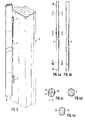
- the torsion bar 4a is an illustration of the torsion bar 4, with its central portion is not shown.
- the torsion bar 4 is made of round steel its end portions 19, 20 are formed two parallel surfaces, so that the End sections 19, 20 in the recesses 12 of the receiving fittings 2 and 3rd are insertable.
- FIG. 4b shows the torsion bar according to FIG. 4a in a view rotated by 90 °.
- the respective parallel surfaces on one end section of the torsion bar 4 are not symmetrical to those of the other end section, but are rotated relative to one another by a certain angle of rotation ⁇ with respect to the longitudinal axis of the torsion bar 4.
- the profile of the torsion bar 4 is explained by the cuts shown in FIGS. 4c, 4d and 4e.
- Fig. 4c shows the torsion bar cut along the line I - I in Fig. 4a, wherein the arrows indicate the direction of view.
- the parallel surfaces 21, 22 of the upper end portion 19 are about the angle of rotation ⁇ , which in the illustrated embodiment is about 10 °, rotated with respect to the axis of symmetry.
- FIG. 4d shows the torsion bar according to FIG. 4a cut along the line II-II, which is not deformed in this area and has a round cross section.
- Fig. 4e shows the torsion bar cut along the line III - III.
- the cross section corresponds identically to that shown in Fig. 4c and also has two parallel surfaces 23, 24 on. Between the upper end portions 19 and the lower End section 20 is accordingly set a certain angle of rotation. In this way, when installing the torsion bar 4, a preload, to be more precise, generate a pretensioning moment that is when the Front door 1 constantly exerts a closing moment.
- the assembly of the torsion bar 4 takes place in a simple manner in which the lower section 20 in the stationary on the door frame 5 attached mounting bracket 3 is used.
- the upper Receptacle fitting 2 is still inserted in the groove 11 of the frame profile 8 not fixed, so that it is vertically movable along the groove 11.
- the recesses 12 are in the upper and lower fitting 2, 3 exactly one above the other. Accordingly, the top end section 19 of the torsion bar 4 are rotated for assembly so that it is in the Support fitting 2 can be used.
- a suitable Tool for example an open-ended wrench, the clear width of which is the distance of the two parallel surfaces 21, 22 corresponds to the upper end section 19 of the torsion bar 4 gripped and twisted until the position of the parallel surfaces 21, 22 exactly the recess 12 of the receiving fitting 2 is aligned.
- the admission fitting 2 can be pushed onto the torsion bar 4, whereby the Assembly is completed.
Landscapes
- Engineering & Computer Science (AREA)
- Structural Engineering (AREA)
- Life Sciences & Earth Sciences (AREA)
- Insects & Arthropods (AREA)
- Pest Control & Pesticides (AREA)
- Architecture (AREA)
- Civil Engineering (AREA)
- Closing And Opening Devices For Wings, And Checks For Wings (AREA)
- Lock And Its Accessories (AREA)
- Underground Structures, Protecting, Testing And Restoring Foundations (AREA)
- Extensible Doors And Revolving Doors (AREA)
- Wing Frames And Configurations (AREA)
Abstract
Description
- Fig. 1
- einen Schnitt durch eine erfindungsgemäße Vorsatztür im Bereich eines Aufnahmebeschlags;
- Fig. 2
- eine perspektivische Teilansicht einer erfindungsgemäßen Vorsatztür, die über einen Torsionsstab mit dem Türrahmen gekoppelt ist;
- Fig. 3
- einen Schnitt durch einen Aufnahmebeschlag für einen Torsionsstab;
- Fig. 4a
- einen Torsionsstab, wobei nur die Endabschnitte dargestellt sind;
- Fig. 4b
- den Torsionsstab nach Fig. 4a in einer um 90° gedrehten Ansicht;
- Fig. 4c
- den Torsionsstab nach Fig. 4a entlang der Linie I - I geschnitten, wobei die Pfeile die Blickrichtung angeben;
- Fig. 4d
- den Torsionsstab nach Fig. 4a entlang der Linie II - II geschnitten;
- Fig. 4e
- den Torsionsstab nach Fig. 4a entlang der Linie III - III geschnitten.
Das Profil des Torsionsstabs 4 wird durch die in den Fig. 4c, 4d und 4e dargestellten Schnitte erläutert.
Claims (16)
- Vorsatztür mit einem Rahmen mit einer darin angebrachten Füllung, der mittels mehrerer Scharniere an einem Türstock oder -rahmen drehbar angebracht oder anbringbar ist, dadurch gekennzeichnet, dass zwischen dem Rahmen (8) und dem Türstock oder -rahmen (5) ein Federelement (4) angebracht oder anbringbar ist, das beim Öffnen der Vorsatztür (1) tordiert wird und bei losgelassener Tür (1) durch die Wirkung der in dem Federelement (4) gespeicherten Energie die Vorsatztür (1) selbsttätig schließt.
- Vorsatztür nach Anspruch 1, dadurch gekennzeichnet, dass das Federelement als Torsionsstab (4) ausgebildet und mit seinem ersten Endabschnitt (19) drehfest mit dem Rahmen (8) der Vorsatztür (1) und mit seinem zweiten Endabschnitt (20) drehfest mit dem Türstock oder -rahmen (5) verbunden bzw. verbindbar ist.
- Vorsatztür nach Anspruch 2, dadurch gekennzeichnet, dass der Torsionsstab (4) zumindest außerhalb der Endabschnitte (19, 20) einen runden Querschnitt aufweist.
- Vorsatztür nach einem der vorangehenden Ansprüche, dadurch gekennzeichnet, dass an der Vorsatztür (1) und an dem Türstock oder - rahmen (5) ein jeweils einen Endabschnitt (19, 20) des Federelements (4) aufnehmender Aufnahmebeschlag (2, 3) angeordnet ist.
- Vorsatztür nach Anspruch 4, dadurch gekennzeichnet, dass zumindest der an der Vorsatztür (1) angeordnete Aufnahmebeschlag (2) entlang des vertikalen Rahmenprofils (8) verschiebbar und lösbar befestigbar ist.
- Vorsatztür nach Anspruch 4 oder 5, dadurch gekennzeichnet, dass zumindest das in der Nähe der Drehachse angeordnete vertikale Rahmenprofil (8) der Vorsatztür (1) eine ein- oder beidseitig hinterschnittene Nut (11) aufweist, in die ein entsprechend gegengleich ausgebildetes Nutstück (16, 17) des Aufnahmebeschlags (2, 3) einsetzbar und mittels eines Befestigungsmittels klemmbar befestigbar ist.
- Vorsatztür nach Anspruch 6, dadurch gekennzeichnet, dass das Befestigungsmittel als Madenschraube ausgebildet ist und in eine Durchgangsbohrung (18) im Bereich des Nutstücks (16, 17) des Aufnahmebeschlags (2) einschraubbar ist.
- Vorsatztür nach einem der Ansprüche 4 bis 7, dadurch gekennzeichnet, dass der an dem Türstock oder -rahmen (5) angeordnete Aufnahmebeschlag (3) ortsfest befestigt bzw. befestigbar ist.
- Vorsatztür nach einem der Ansprüche 2 bis 8, dadurch gekennzeichnet, dass der Torsionsstab (4) unter einer Vorspannung montierbar ist.
- Vorsatztür nach einem der Ansprüche 2 bis 9, dadurch gekennzeichnet, dass an jedem Endabschnitt (19, 20) des Torsionsstabs (4) zwei zueinander parallele Flächen (21, 22, 23, 24) durch Umformen ausgebildet sind, die in entsprechend gegengleich geformte Ausnehmungen (12) der Aufnahmebeschläge (2, 3) einsteckbar sind.
- Vorsatztür nach Anspruch 10, dadurch gekennzeichnet, dass die parallelen Flächen (21, 22) des ersten Endabschnitts (19) des Torsionsstabs (4) gegenüber den Flächen (23, 24) des zweiten Endabschnitts (20) bezüglich der Längsachse um einen bestimmten Drehwinkel verdreht sind.
- Vorsatztür nach Anspruch 11, dadurch gekennzeichnet, dass der Drehwinkel 5° bis 20°, vorzugsweise 10° beträgt.
- Vorsatztür nach einem der Ansprüche 2 bis 12, dadurch gekennzeichnet, dass die Federkonstante durch die Länge des Torsionsstabs (4) und/oder durch die Wahl des Querschnitts einstellbar ist.
- Vorsatztür nach einem der vorangehenden Ansprüche, dadurch gekennzeichnet, dass der maximale Öffnungswinkel der Vorsatztür (1) 110° bis 130°, insbesondere 120° beträgt.
- Vorsatztür nach einem der Ansprüche 2 bis 14, dadurch gekennzeichnet, dass der Torsionsstab (4) aus Stahl ist.
- Vorsatztür nach einem der Ansprüche 4 bis 15, dadurch gekennzeichnet, dass die Aufnahmebeschläge (2, 3) aus einer Leichtmetalllegierung sind.
Applications Claiming Priority (2)
| Application Number | Priority Date | Filing Date | Title |
|---|---|---|---|
| DE10039829A DE10039829B4 (de) | 2000-08-16 | 2000-08-16 | Vorsatztür mit Schließmechanismus |
| DE10039829 | 2000-08-16 |
Publications (3)
| Publication Number | Publication Date |
|---|---|
| EP1180575A2 true EP1180575A2 (de) | 2002-02-20 |
| EP1180575A3 EP1180575A3 (de) | 2006-07-26 |
| EP1180575B1 EP1180575B1 (de) | 2008-01-23 |
Family
ID=7652485
Family Applications (1)
| Application Number | Title | Priority Date | Filing Date |
|---|---|---|---|
| EP01119447A Expired - Lifetime EP1180575B1 (de) | 2000-08-16 | 2001-08-13 | Vorsatztür mit Schliessmechanismus |
Country Status (3)
| Country | Link |
|---|---|
| EP (1) | EP1180575B1 (de) |
| AT (1) | ATE384851T1 (de) |
| DE (2) | DE10039829B4 (de) |
Cited By (1)
| Publication number | Priority date | Publication date | Assignee | Title |
|---|---|---|---|---|
| EP1873346A3 (de) * | 2006-06-30 | 2008-09-10 | tesa AG | Vorrichtung zum Öffnen und Schließen einer Gebäudeöffnung |
Families Citing this family (4)
| Publication number | Priority date | Publication date | Assignee | Title |
|---|---|---|---|---|
| DE102006005375B4 (de) * | 2006-02-03 | 2008-11-13 | Lämmermann, Gerd | Insektenschutztür |
| DE102007007170A1 (de) | 2007-02-09 | 2008-08-14 | Proflytec Insektenschutzsystemtechnik Gmbh | Vorsatztür für den Insektenschutz |
| DE102008045772A1 (de) | 2008-09-04 | 2010-03-11 | Warema Renkhoff Gmbh | Scharnier mit Rückstellfeder und Schließelement mit solchen Scharnieren |
| US11035164B2 (en) | 2019-07-10 | 2021-06-15 | Deere & Company | Adjustable torsional door rod |
Family Cites Families (7)
| Publication number | Priority date | Publication date | Assignee | Title |
|---|---|---|---|---|
| DE829413C (de) * | 1950-03-18 | 1952-01-24 | Adolf Zaiser Maschinenfabrik G | Tuerschliesser |
| DE3139277A1 (de) * | 1981-10-02 | 1983-04-21 | Reinhard 2956 Moormerland Badewien | Insektenschutzvorrichtung fuer tueren |
| DE8702971U1 (de) * | 1987-02-26 | 1987-04-16 | Huwil-Werke GmbH Möbelschloß- und Beschlagfabriken, 5207 Ruppichteroth | Tür- oder Klappenscharnier |
| DE4308944C3 (de) * | 1993-03-19 | 2002-01-24 | Helmut Siegel | Insektenschutzeinrichtung |
| DE4426274A1 (de) * | 1994-07-25 | 1996-02-01 | Wilhelm Saar | Türschließer |
| DE19518450A1 (de) * | 1995-05-19 | 1996-11-21 | Bel Air Art Bilderrahmen Gmbh | Möbeltür mit einem Scharnier |
| DE19850032C2 (de) * | 1998-10-30 | 2002-02-07 | Neher Systeme Gmbh & Co Kg | Insektenschutzvorrichtung |
-
2000
- 2000-08-16 DE DE10039829A patent/DE10039829B4/de not_active Expired - Lifetime
-
2001
- 2001-08-13 AT AT01119447T patent/ATE384851T1/de active
- 2001-08-13 DE DE50113525T patent/DE50113525D1/de not_active Expired - Lifetime
- 2001-08-13 EP EP01119447A patent/EP1180575B1/de not_active Expired - Lifetime
Cited By (1)
| Publication number | Priority date | Publication date | Assignee | Title |
|---|---|---|---|---|
| EP1873346A3 (de) * | 2006-06-30 | 2008-09-10 | tesa AG | Vorrichtung zum Öffnen und Schließen einer Gebäudeöffnung |
Also Published As
| Publication number | Publication date |
|---|---|
| ATE384851T1 (de) | 2008-02-15 |
| DE50113525D1 (de) | 2008-03-13 |
| DE10039829A1 (de) | 2002-02-28 |
| EP1180575B1 (de) | 2008-01-23 |
| DE10039829B4 (de) | 2005-01-05 |
| EP1180575A3 (de) | 2006-07-26 |
Similar Documents
| Publication | Publication Date | Title |
|---|---|---|
| EP3346078B1 (de) | Zimmertür | |
| EP3363976B1 (de) | Drehöffnungsbegrenzungsanordnung für ein fenster oder eine tür zur begrenzung der drehöffnungsbewegung eines flügels eines fensters oder einer tür | |
| DE3872442T2 (de) | Drehbeschlag eines drehkippfluegels einer tuer eines fensters oder von aehnlichem. | |
| EP1223276B1 (de) | Bandanordnung für Türen, Fenster und dergleichen | |
| EP2504511B1 (de) | Bandteil eines scharnierbandes | |
| DE3104973A1 (de) | "aufschraubband, insbesondere fuer schwere fenster- oder tuerfluegel mit kunststoffprofilen" | |
| DE19521601C1 (de) | Fenster, Tür oder dergleichen | |
| EP1180575B1 (de) | Vorsatztür mit Schliessmechanismus | |
| WO2019038030A1 (de) | Fingerschutzvorrichtung | |
| EP0844348A1 (de) | Band für Türen oder Fenster | |
| EP2099989B1 (de) | Treibstangengetriebe | |
| DE202009003119U1 (de) | Beschlag für die Befestigung einer Duschtür | |
| EP1223278B1 (de) | Bandanordnung für Türen, Fenster und dergleichen | |
| DE3150029C2 (de) | Treibstangenverschluß mit Eckumlenkung für Fenster und Türen od.dgl. | |
| EP1659246A1 (de) | Scharnierbeschlag für Fensterläden | |
| EP1746235B1 (de) | Beschlaganordnung | |
| EP0730074B1 (de) | Kantriegelbeschlag für Standflügel von doppelflügeligen Türen | |
| DE102007025857A1 (de) | Gelenkband für Türen oder Fenster | |
| EP0913546B1 (de) | Getriebebeschlag für einen Flügelrahmen | |
| EP1813754B1 (de) | Obertürschliesser | |
| DE19918283B4 (de) | Tür- oder Fensterdrehband | |
| EP2467549A2 (de) | BAUELEMENT, INSBESONDERE FENSTER ODER TÜR, MIT SCHLIEßVORRICHTUNG | |
| AT204439B (de) | Verschlußanordnung für Fenster od. dgl. | |
| DE60115160T2 (de) | Zwischenbeschlag für Tür oder Fenster für nicht sichtbaren Scharnierbeschlag | |
| DE4236431A1 (de) |
Legal Events
| Date | Code | Title | Description |
|---|---|---|---|
| PUAI | Public reference made under article 153(3) epc to a published international application that has entered the european phase |
Free format text: ORIGINAL CODE: 0009012 |
|
| AK | Designated contracting states |
Kind code of ref document: A2 Designated state(s): AT BE CH CY DE DK ES FI FR GB GR IE IT LI LU MC NL PT SE TR |
|
| AX | Request for extension of the european patent |
Free format text: AL;LT;LV;MK;RO;SI |
|
| PUAL | Search report despatched |
Free format text: ORIGINAL CODE: 0009013 |
|
| AK | Designated contracting states |
Kind code of ref document: A3 Designated state(s): AT BE CH CY DE DK ES FI FR GB GR IE IT LI LU MC NL PT SE TR |
|
| AX | Request for extension of the european patent |
Extension state: AL LT LV MK RO SI |
|
| 17P | Request for examination filed |
Effective date: 20060816 |
|
| 17Q | First examination report despatched |
Effective date: 20061018 |
|
| AKX | Designation fees paid |
Designated state(s): AT BE CH CY DE DK ES FI FR GB GR IE IT LI LU MC NL PT SE TR |
|
| 17Q | First examination report despatched |
Effective date: 20061018 |
|
| GRAP | Despatch of communication of intention to grant a patent |
Free format text: ORIGINAL CODE: EPIDOSNIGR1 |
|
| GRAS | Grant fee paid |
Free format text: ORIGINAL CODE: EPIDOSNIGR3 |
|
| GRAA | (expected) grant |
Free format text: ORIGINAL CODE: 0009210 |
|
| AK | Designated contracting states |
Kind code of ref document: B1 Designated state(s): AT BE CH CY DE DK ES FI FR GB GR IE IT LI LU MC NL PT SE TR |
|
| REG | Reference to a national code |
Ref country code: GB Ref legal event code: FG4D Free format text: NOT ENGLISH |
|
| REG | Reference to a national code |
Ref country code: CH Ref legal event code: EP |
|
| REG | Reference to a national code |
Ref country code: IE Ref legal event code: FG4D Free format text: LANGUAGE OF EP DOCUMENT: GERMAN |
|
| REF | Corresponds to: |
Ref document number: 50113525 Country of ref document: DE Date of ref document: 20080313 Kind code of ref document: P |
|
| NLV1 | Nl: lapsed or annulled due to failure to fulfill the requirements of art. 29p and 29m of the patents act | ||
| PG25 | Lapsed in a contracting state [announced via postgrant information from national office to epo] |
Ref country code: ES Free format text: LAPSE BECAUSE OF FAILURE TO SUBMIT A TRANSLATION OF THE DESCRIPTION OR TO PAY THE FEE WITHIN THE PRESCRIBED TIME-LIMIT Effective date: 20080504 Ref country code: FI Free format text: LAPSE BECAUSE OF FAILURE TO SUBMIT A TRANSLATION OF THE DESCRIPTION OR TO PAY THE FEE WITHIN THE PRESCRIBED TIME-LIMIT Effective date: 20080123 |
|
| GBV | Gb: ep patent (uk) treated as always having been void in accordance with gb section 77(7)/1977 [no translation filed] | ||
| PG25 | Lapsed in a contracting state [announced via postgrant information from national office to epo] |
Ref country code: PT Free format text: LAPSE BECAUSE OF FAILURE TO SUBMIT A TRANSLATION OF THE DESCRIPTION OR TO PAY THE FEE WITHIN THE PRESCRIBED TIME-LIMIT Effective date: 20080623 |
|
| REG | Reference to a national code |
Ref country code: IE Ref legal event code: FD4D |
|
| PG25 | Lapsed in a contracting state [announced via postgrant information from national office to epo] |
Ref country code: SE Free format text: LAPSE BECAUSE OF FAILURE TO SUBMIT A TRANSLATION OF THE DESCRIPTION OR TO PAY THE FEE WITHIN THE PRESCRIBED TIME-LIMIT Effective date: 20080423 Ref country code: NL Free format text: LAPSE BECAUSE OF FAILURE TO SUBMIT A TRANSLATION OF THE DESCRIPTION OR TO PAY THE FEE WITHIN THE PRESCRIBED TIME-LIMIT Effective date: 20080123 Ref country code: DK Free format text: LAPSE BECAUSE OF FAILURE TO SUBMIT A TRANSLATION OF THE DESCRIPTION OR TO PAY THE FEE WITHIN THE PRESCRIBED TIME-LIMIT Effective date: 20080123 Ref country code: IE Free format text: LAPSE BECAUSE OF FAILURE TO SUBMIT A TRANSLATION OF THE DESCRIPTION OR TO PAY THE FEE WITHIN THE PRESCRIBED TIME-LIMIT Effective date: 20080123 |
|
| EN | Fr: translation not filed | ||
| PLBE | No opposition filed within time limit |
Free format text: ORIGINAL CODE: 0009261 |
|
| STAA | Information on the status of an ep patent application or granted ep patent |
Free format text: STATUS: NO OPPOSITION FILED WITHIN TIME LIMIT |
|
| 26N | No opposition filed |
Effective date: 20081024 |
|
| PG25 | Lapsed in a contracting state [announced via postgrant information from national office to epo] |
Ref country code: GB Free format text: LAPSE BECAUSE OF FAILURE TO SUBMIT A TRANSLATION OF THE DESCRIPTION OR TO PAY THE FEE WITHIN THE PRESCRIBED TIME-LIMIT Effective date: 20080123 |
|
| PG25 | Lapsed in a contracting state [announced via postgrant information from national office to epo] |
Ref country code: MC Free format text: LAPSE BECAUSE OF NON-PAYMENT OF DUE FEES Effective date: 20080831 |
|
| REG | Reference to a national code |
Ref country code: CH Ref legal event code: PL |
|
| PG25 | Lapsed in a contracting state [announced via postgrant information from national office to epo] |
Ref country code: FR Free format text: LAPSE BECAUSE OF FAILURE TO SUBMIT A TRANSLATION OF THE DESCRIPTION OR TO PAY THE FEE WITHIN THE PRESCRIBED TIME-LIMIT Effective date: 20081114 |
|
| PG25 | Lapsed in a contracting state [announced via postgrant information from national office to epo] |
Ref country code: LI Free format text: LAPSE BECAUSE OF NON-PAYMENT OF DUE FEES Effective date: 20080831 Ref country code: CH Free format text: LAPSE BECAUSE OF NON-PAYMENT OF DUE FEES Effective date: 20080831 |
|
| PG25 | Lapsed in a contracting state [announced via postgrant information from national office to epo] |
Ref country code: CY Free format text: LAPSE BECAUSE OF FAILURE TO SUBMIT A TRANSLATION OF THE DESCRIPTION OR TO PAY THE FEE WITHIN THE PRESCRIBED TIME-LIMIT Effective date: 20080123 Ref country code: BE Free format text: LAPSE BECAUSE OF NON-PAYMENT OF DUE FEES Effective date: 20080831 |
|
| PG25 | Lapsed in a contracting state [announced via postgrant information from national office to epo] |
Ref country code: IT Free format text: LAPSE BECAUSE OF FAILURE TO SUBMIT A TRANSLATION OF THE DESCRIPTION OR TO PAY THE FEE WITHIN THE PRESCRIBED TIME-LIMIT Effective date: 20080123 |
|
| PG25 | Lapsed in a contracting state [announced via postgrant information from national office to epo] |
Ref country code: LU Free format text: LAPSE BECAUSE OF NON-PAYMENT OF DUE FEES Effective date: 20080813 |
|
| PG25 | Lapsed in a contracting state [announced via postgrant information from national office to epo] |
Ref country code: TR Free format text: LAPSE BECAUSE OF FAILURE TO SUBMIT A TRANSLATION OF THE DESCRIPTION OR TO PAY THE FEE WITHIN THE PRESCRIBED TIME-LIMIT Effective date: 20080123 |
|
| PG25 | Lapsed in a contracting state [announced via postgrant information from national office to epo] |
Ref country code: GR Free format text: LAPSE BECAUSE OF FAILURE TO SUBMIT A TRANSLATION OF THE DESCRIPTION OR TO PAY THE FEE WITHIN THE PRESCRIBED TIME-LIMIT Effective date: 20080424 |
|
| PGFP | Annual fee paid to national office [announced via postgrant information from national office to epo] |
Ref country code: DE Payment date: 20200916 Year of fee payment: 20 |
|
| PGFP | Annual fee paid to national office [announced via postgrant information from national office to epo] |
Ref country code: AT Payment date: 20200828 Year of fee payment: 20 |
|
| REG | Reference to a national code |
Ref country code: DE Ref legal event code: R071 Ref document number: 50113525 Country of ref document: DE |
|
| REG | Reference to a national code |
Ref country code: AT Ref legal event code: MK07 Ref document number: 384851 Country of ref document: AT Kind code of ref document: T Effective date: 20210813 |